STOP AND START
-
FUNCTION OF MAIN COMPONENTS
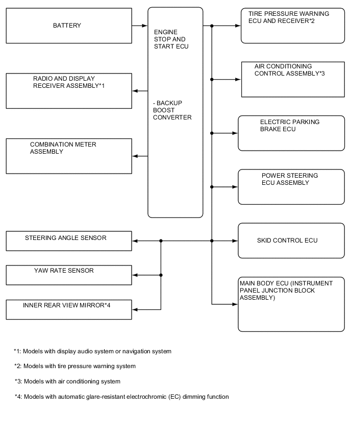
Component Function Engine Stop and Start ECU Sends either an engine stop or restart signal to the ECM according to the signals from each sensor and switch. Engine Stop and Start ECU (Backup Boost Converter) Supplies battery voltage to help make up for the voltage drop that occurs when the engine is restarted, preventing the operation of various systems from being interrupted due to low battery voltage. Clutch Start Switch Assembly Recognizes that the clutch pedal is depressed and sends a signal to the engine stop and start ECU. Neutral Position Switch Recognizes that the shift lever is in N and sends a signal to the engine stop and start ECU. Brake Vacuum Pressure Sensor Detects the brake booster vacuum pressure and sends a signal to the engine stop and start ECU. Hood Lock Assembly (Engine Hood Courtesy Switch) Detects whether the hood is open or closed and sends a signal to the engine stop and start ECU. Air Conditioning Amplifier Assembly*1 Sends an outside temperature signal and A/C switch signal to the engine stop and start ECU. Combination Meter Assembly Stop and Start Indicator Light
-
Turns on when the engine is stopped due to stop and start system control.
-
If the shift lever is moved out of N without the clutch pedal depressed during idling stop, the buzzer sounds and the stop and start indicator light blinks at the same time.* 2
Stop and Start Cancel Indicator Light Turns on to inform the driver that the system has been disabled when stop and start system operation is prohibited by the stop and start system cancel switch assembly. If a system malfunction is detected or the operation count of the starter assembly exceeds a threshold, the stop and start cancel indicator light blinks to inform the driver. Multi-information Display
-
Displays the current idling stop time, the idling stop time since the ignition switch was turned from ON to off, and the total idling stop time since the last time the idling stop time was reset.
-
Displays the settings of the stop and start system or warning information, etc.
Stop and Start System Cancel Switch (Ecorun Cancel Switch Assembly) Operation of the system can be canceled by pressing the stop and start system cancel switch (ecorun cancel switch assembly). Pressing the switch again or turning the power source off and back on restores the operation of the system. Battery Current Sensor Assembly
- Battery Temperature Sensor
Detects the battery temperature and how much power is being charged to or discharged from the battery and sends signals to the power management control ECU. These signals are used to protect the battery. ECM Sends various information about engine conditions to the engine stop and start ECU. Brake Actuator Assembly (Skid Control ECU) Sends a vehicle speed signal to the engine stop and start ECU. Airbag Sensor Assembly Sends airbag deployment information in the event of a collision and a deceleration signal to the engine stop and start ECU. Main Body ECU (Instrument Panel Junction Block Assembly) Sends a front door courtesy light switch signal and front seat belt buckle switch (driver) signal to the engine stop and start ECU. Power Steering ECU Assembly
-
Sends an electrical power steering assist signal to the engine stop and start ECU.
-
Sends a power steering torque sensor signal to the engine stop and start ECU.
Electric Parking Brake ECU Sends an electric parking brake signal to the engine stop and start ECU. Tech Tips
*1: Models with air conditioning system
*2: If the shift lever is moved back to N, the buzzer stops sounding and the stop and start indicator light stops blinking.
-
-
OPERATING CONDITION
-
Operating Conditions at Engine Stop and Restart
-
The engine may stop if all of the following conditions are detected:
Item Operating Condition Idle Stop Engine Coolant Temperature A predetermined temperature*1 to 105°C (221°F) Outside Temperature -5°C (23°F) or more Driver's Door Closed Driver's Seat Belt Fastened Brake Booster Vacuum Sufficient brake booster vacuum Stop and Start System Cancel Switch (Ecorun Cancel Switch Assembly) Off condition Road Gradient -8° to 8° Vehicle Speed 0 km/h (0 mph) Engine Speed 1250 r/min or less Accelerator Pedal Condition Released Clutch Pedal Released Shift Lever Position Neutral Engine Hood Closed Battery Voltage Minimum input voltage to the starter is 7.37 V or more. Battery Temperature -10°C to 70°C (50°F to 158°F)*2 Battery Integrated Current*3
-
0 A-sec or more: After the engine starts by ignition switch operation.
-
After the integrated current value has increased to 0 A-sec or more at least once after the ignition switch is turned to ON:
-
More than -6451 A-sec: When status of battery charge control is charge control coordination mode or low temperature mode.*4
-
More than -1152 A-sec: When status of battery charge control is start standalone mode, stop and start restriction mode or temperature high/low mode.*4
Air Conditioning*5 Off, or on with an outside temperature of 23°C (73.4°F) or lower and an evaporator temperature of 9°C (48°F) or lower. Heater Off, or on with an outside temperature of 5°C (41°F) or higher and an engine coolant temperature of 55°C (131°F) or higher, or a cabin temperature -5°C or less than the set temperature (normal mode setting). Steering Steering operation torque is lower than 2.7 N*m. Electric Parking Brake The electric parking brake is fully applied or released.
-
*1: The lowest operating temperature is determined by environmental conditions.
-
*2: When the battery temperature becomes -15°C or lower or 75°C or higher, control is prohibited. After control is prohibited and the battery temperature rises to -10°C or higher or falls to 70°C or lower, control is performed.
-
*3: Regarding Battery Integrated Current
In the stop and start system, the engine stop and start ECU switches the system control mode (stop and start system control permitted/prohibited) based on the battery condition (charge/discharge condition) to protect the battery and to ensure stable engine restarting performance. The battery charge-discharge condition is determined from the integrated current value calculated from the battery current sensor signal. The integrated current value is obtained by multiplying the current (ampere) detected by the battery current sensor by the time (seconds), and the resulting value is expressed in the unit A-sec. This can be measured by the Global TechStream (GTS). The engine stop and start ECU determines the power charge based on the integrated current value and prohibits stop and start system control if the value is below the threshold, because the battery might not be able to start the engine. The threshold varies according to the battery temperature and battery charge condition.
-
*4: After the integrated current value becomes -6451 A-sec or less or -1152 A-sec or less, respectively, in order to charge the battery, control is prohibited until the value becomes -5299 A-sec or more or 0 A-sec or more, respectively.
-
*5: Models with air conditioning system
-
-
The engine will restart if any of the following conditions are detected:
Item Operating Condition Engine Restart Brake Booster Vacuum The brake booster vacuum is insufficient. Air Conditioning*1 When all of the following conditions are met:
- The blower switch is on.
- The evaporator temperature meets or exceeds the threshold, or a certain period of time elapses after idling stop is performed (threshold changes due to the environment around the vehicle).
Heater Tthe timer in the air conditioning amplifier assembly operates. Air Conditioning*1/Heater
-
The A/C switch is turned on.
-
When the stop and start setting changes from "Extended mode" to "Normal" mode.
Stop and Start System Cancel Switch (Ecorun Cancel Switch Assembly) The stop and start system cancel switch (ecorun cancel switch assembly) is turned on. Power Heater Switch*2 The heater switch assembly is turned on. Battery
-
The battery voltage is less 11.4 V
-
The battery integrated current drops to below the threshold value.
Driver's Door The driver's door is opened. Driver's Seat Belt The driver's seat belt is unfastened. Vehicle Speed A vehicle speed signal is input. Clutch Pedal The clutch pedal is depressed. Steering Wheel The steering wheel is turned with a torque of 6 N*m or more. Electric Parking Brake Release operation is performed while the parking brake is locked.
-
*1: Models with air conditioning system
-
*2: Models with combustion type power heater
-
*3: Models with automatic air conditioning system
-
-
-
-
FUNCTION
-
Settings of Stop and Start System
-
Using the steering pad switch on the steering pad switch assembly and the multi-information display on the combination meter assembly, the engine stop operation time due to stop and start control when the air conditioning system is on can be changed between Normal and Long (the stop and start system has priority).
-
-
-
SYSTEM CONTROL
-
System Prohibit Control
-
For safety, battery protection, comfort and ECU learning reasons, the engine stop and start ECU prohibits stop and start system operation if any one of the following conditions is met:
Prohibition Reason Condition Safety If the engine is started with the hood open, such as when jump starting, engine restart operation cannot be ensured. Therefore, stop and start system operation will be prohibited. The operation of the system will be restored on the next trip. If the driver door or hood is opened before the engine stops, stop and start system operation will be prohibited. The brake booster vacuum is insufficient. If the engine stop and start ECU receives an airbag deployment signal in the event of a collision, stop and start system operation will be prohibited. If the driver's seat belt is unfastened before the engine stops. When the engine stop and start ECU determines that the electric parking brake is switching between applied and released, the ECU prohibits stop and start system operation. Battery Protection While recharging, stop and start system operation will be disabled. The recharging continues for 0.5 to 1 hour, and is carried out approximately every 20 hours or driving. When the idling stop rate becomes higher than the predetermined rate, stop and start system operation will be disabled. When the battery becomes low and the battery integrated current value drops to below the threshold value, stop and start operation will be disabled. Comfort If the air conditioning is on when the outside temperature is high and the evaporator temperature is high, stop and start system operation will be prohibited.*1 If the heater is on when the outside temperature is low and the engine coolant temperature is low, stop and start system operation will be prohibited. If the front DEF switch (air conditioning control assembly) and blower switch (air conditioning control assembly) are on, stop and start system operation will be prohibited. If the power heater switch *2 is turned on, stop and start system operation will be prohibited. Operability When the steering wheel is operated at a torque of 2.7 N*m or more, the stop and start system operation will be prohibited in order to suppress excessively large fluctuations of the torque assist carried out by the EPS.
-
*1: Models with air conditioning system
-
*2: Models with combustion type power heater
-
-
-
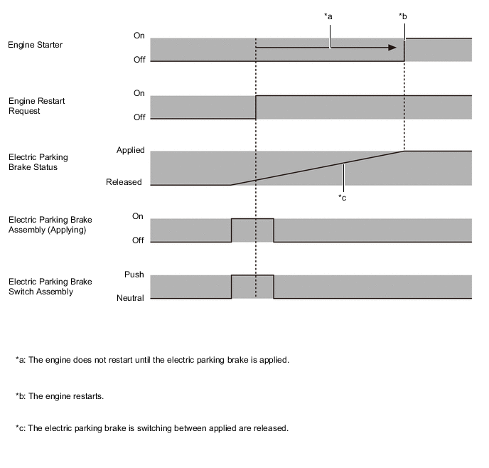
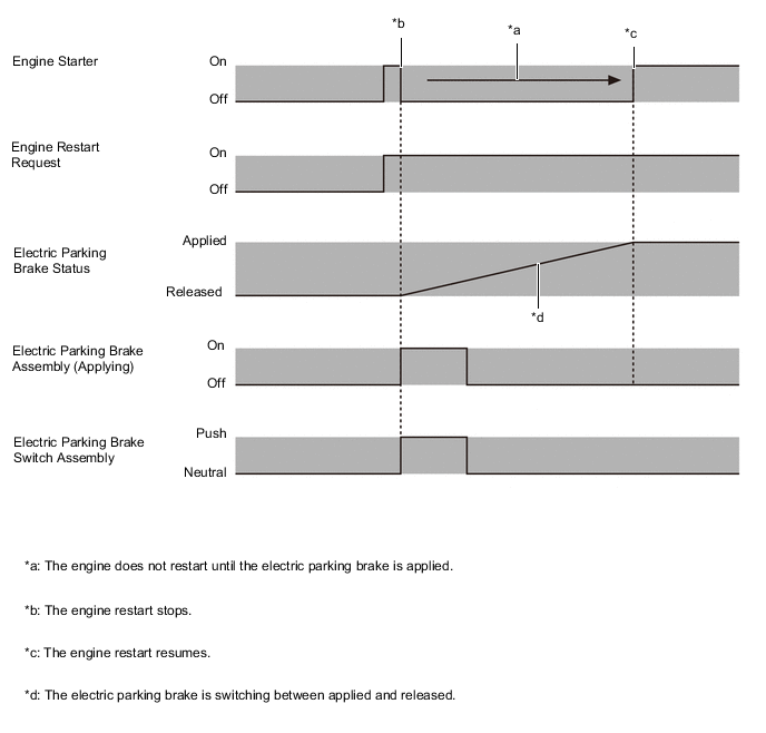
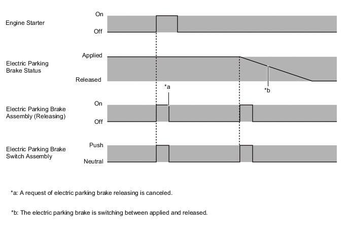
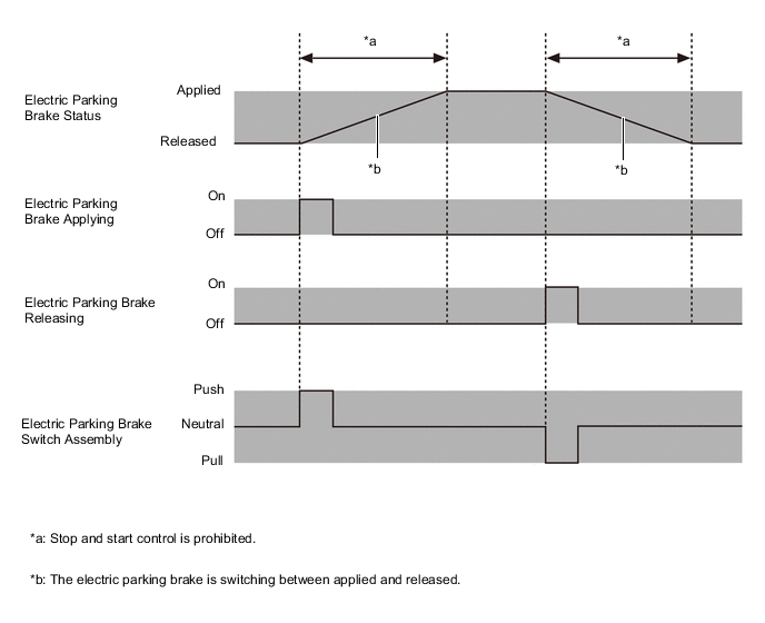
Idling Stop Control based on Electric Parking Brake Operation Condition
-
The following operation priority orders have been set to prevent the engine from restarting while the electric parking brake is switching between applied and released.
Stop and Start Condition Idling Engine Stop Engine Restarting Electrical Parking Brake Condition Request of Applying Electric Parking Brake: Operate Case A)
Electric Parking Brake: Operate
Stop and Start: Prohibition of Engine Restarting
Case B)
Electric Parking Brake: Operate Stop and Start: Stop of Engine Restarting
Request of Releasing Electric Parking Brake: Operate Case C)
Electric Parking Brake: Not Operate
Stop and Start: Engine Restarting
Case C)
Electric Parking Brake: Not Operate
Stop and Start: Engine Restarting
-
Case A: The engine will not restart until electric parking brake is applied.
-
Case B: When there is a request of electric parking brake applying while engine is restarting, engine restating is stopped and electric parking brake is applying.
-
Case C: When there is a request of electric parking brake releasing while engine is stopped by stop and start system, request of electric parking brake releasing is canceled and engine is restarting.
-
-
While the electric parking brake is switching between applied and released, stop and start system operation is prohibited.
-
-
Warning Control
-
If any of the following operations are performed while the engine is stopped due to system control, the system will not restart the engine. The driver will be warned by a buzzer, the engine will be regarded as stalled, or the engine will be restarted.
Operation Warning Control Driver door is opened. The engine changes to restarted. Driver seat belt is unbuckled. The engine changes to restarted. Hood is opened. The engine changes to stalled. Shift lever is moved without depressing the clutch pedal.
-
Buzzer sounds.
-
Stop and start indicator light blinks.
-
-
-
-
CONSTRUCTION
-
Backup Boost Converter
-
The backup boost converter uses a semiconductor relay. The semiconductor relay also functions as a fuse. When overcurrent is detected, the relay is turned off to protect the circuit.
-
The backup boost converter supplies battery voltage to help make up for the voltage drop that occurs when the engine is restarted. This prevents the operation of the following equipment from being interrupted due to low battery voltage:
-
Radio and Display Receiver Assembly*1
-
Tire Pressure Warning ECU and Receiver*2
-
Air Conditioning Control Assembly*3
-
Steering Angle Sensor
-
Yaw Rate Sensor
-
Inner Rear View Mirror*4
-
Electric Parking Brake ECU
-
Power Steering ECU Assembly
-
Skid Control ECU
-
Main Body ECU (Instrument Panel Junction Block Assembly)
-
Combination Meter Assembly
-
*1: Models with navigation system or display audio system
-
*2: Models with tire pressure warning system
-
*3: Models with air conditioning system
-
*4: Models with automatic glare-resistant electrochromic (EC) dimming function
-
-
-
-
OPERATION
-
Combination Meter Assembly
-
The combination meter assembly receives the idling on/off signals from the engine stop and start ECU.
-
The current idling stop time, the idling stop time since the ignition switch was turned from ON to off, and the total idling stop time since the last time the idling stop time was reset can be displayed on the multi-information display.
-
The driver is informed of the system operation status and warnings by the illumination of the stop and start indicator light, the illumination and flashing of the stop and start cancel indicator light, the display of items on the multi-information display and the sounding of the multi buzzer.
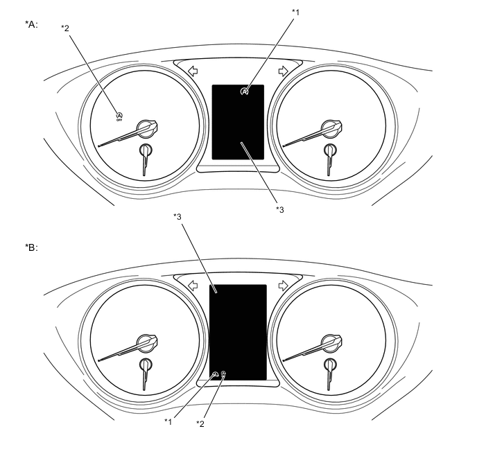
Text in Illustration *A Models with Optitron Type Combination Meter Assembly with Monochrome Multi-information Display *B Models with Optitron Type Combination Meter Assembly with TFT Color Multi-information Display *1 Stop and Start Indicator Light *2 Stop and Start Cancel Indicator Light *3 Multi-information Display - - Stop and Start Indicator Light Operation Item Condition Stop and Start Indicator Light Buzzer System Operating (Engine is stopped) The vehicle is operating normally. Illuminates Does not sound The shift lever is operated without depressing the clutch pedal. Blinks* Sounds
-
*: The blinking interval is 0.15 seconds.
Stop and Start Cancel Indicator Light Operation Condition Stop and Start Cancel Indicator Light The vehicle is stopped and system operation conditions are met. OFF While the stop and start system is preventing the engine stop control from operating. Illuminates When the stop and start system cancel switch (ecorun cancel switch assembly) is ON. When any Diagnostic Trouble Codes (DTCs) are detected. Blinks* When the number of times the starter assembly has been operated exceeds the threshold.
-
*: The blinking interval is 0.5 seconds.
Multi-information Display Operation (Models with Option Type Combination Meter Assembly with Monochrome Multi-information Display) Condition Multi-information Display A system malfunction is detected. STOP & START SYSTEM MALFUNCTION INSPECT AT DEALER. The shift lever is operated without depressing the clutch pedal. STOP & START SYSTEM ACTIVE. SHIFT TO N AND DEPRESS CLUTCH TO START. The stop and start system preferred setting has been changed from "Extended" to "Normal". BALANCES STOP & START AND A/C OUTPUT. The stop and start system preferred setting has been changed from "Normal" to "Extended". PROLONGS STOP & START AND REDUCES A/C OUTPUT. Multi-information Display Operation (Models with Optitoron Type Combination Meter Assembly with TFT Color Multi-information Display) Condition Multi-information Display The engine cannot be stopped by the stop and start system.
-
The air conditioning system is being used when the ambient temperature is high or low.
-
The windshiled defogger system is turned on.
-
The power heater is turned on.
For climate control
-
The battery charge amount may be low.
-
A refresh charge may be occurring (occurs a short time after replacing the battery, when removing battery terminals, etc.)
-
The engine may have been started with the hood opened.
-
The battery may be cold.
-
The battery may be extremely hot.
Battery charging
-
The brake booster load is decreased.
-
The vehicle is driven at a high elevation.
For brake system The driver seat belt is not fastended . Driver seat belt unbuckled The hood is opened. Bonnet open The engine automatically restarts while stopped by the stop and start system.
-
The air conditioning system is turned on or the air conditioning is being used.
-
The windshield defogger is turned on.
-
The power heater is turned on.
For climate control The brake pedal is strongly depressed further or pumped. For brake system The battery charge amount may be low. Battery charging The steering wheel is turned. Steering wheel turned The driver seat belt is not fastended. Driver seat belt unbuckled -
-
-
-
DIAGNOSIS
-
When the engine stop and start ECU detects a malfunction and CAN communication is normal, the engine stop and start ECU records information related to the malfunction. Furthermore, the stop and start cancel indicator light in the combination meter assembly blinks to inform the driver that CAN communication is normal.
-
The engine stop and start ECU also stores Diagnostic Trouble Codes (DTCs) related to malfunctions. DTCs can be read using the Global TechStream (GTS).
-