CRUISE CONTROL SYSTEM
-
FUNCTION OF MAIN COMPONENTS
-
Constant Speed Control Mode
Component Function Cruise Control Switch Main Switch Turns on/off the power to the constant speed control mode. CANCEL Switch A cancel signal can be output to the ECM through the operation of this switch. RES/+ Switch The acceleration function and resume control function can be performed by operating this switch. A signal is output to the ECM when this switch is operated. SET/- Switch The deceleration function and set control function can be performed by operating this switch. A signal is output to the ECM when this switch is operated. Speed Sensor Detects the vehicle speed and transmits a signal via the skid control ECU to the combination meter assembly. Injector Adjusts the fuel injection volume based on the signals from the ECM. Stop Light Switch Assembly Detects the depressing of the brake pedal and transmits a signal to the ECM. Clutch (Brake) Pedal Stroke Sensor Assembly Detects the depressing of the clutch pedal and transmits a signal via the electric parking brake ECU to the ECM. Combination Meter Assembly Cruise Main Indicator Light
-
Illuminates when the main switch on the cruise control switch has been pressed to turn the constant speed control mode on.
-
If the ECM detects a malfunction, this light turns off to warn the driver.
Cruise SET Indicator Light Illuminates when the SET/- switch on the cruise control switch has been pressed to turn the constant speed control mode set. Multi-information Display Displays a warning when a malfunction occurs in the cruise control system. VSC OFF Switch Detects the VSC off signal and outputs it to the skid control ECU. ECM
-
Controls the constant speed control mode in accordance with signals from the switches and sensors.
-
If the ECM detects a malfunction in the cruise control system, it will store a Diagnostic Trouble Code (DTC).
-
-
Speed Limiter Control Mode
Component Function Speed Limiter Main Switch Turns on/off the power to the speed limiter control mode. Cruise Control Switch CANCEL Switch A cancel signal can be output to the ECM through the operation of this switch. RES/+ Switch The acceleration function and resume control function can be performed by operating this switch. A signal is output to the ECM when this switch is operated. SET/- Switch The deceleration function and set control function can be performed by operating this switch. A signal is output to the ECM when this switch is operated. Speed Sensor Detects the vehicle speed and transmits a signal via the skid control ECU to the combination meter assembly. Injector Adjusts the fuel injection volume based on the signals from the ECM. Accelerator Pedal Assembly
- Position Sensor
Detects whether the accelerator pedal is in the kick down mode and transmits signals to the ECM. Clutch (Brake) Pedal Stroke Sensor Assembly Detects the depressing of the clutch pedal and transmits a signal via the electric parking brake ECU to the ECM. Combination Meter Assembly Speed Limiter Main Indicator Light
-
Illuminates when the speed limiter main switch has been pressed to turn the speed limiter control mode on.
-
If the ECM detects a malfunction, this light turns off to warn the driver.
Multi-information Display Shows the state of the speed limiter control mode. ECM
-
Controls the speed limiter control mode in accordance with signals from the switches and sensors.
-
If the ECM detects a malfunction in the cruise control system, it will store a Diagnostic Trouble Code (DTC).
-
-
-
FUNCTION
-
The cruise control system has the following functions:
Mode Function Outline Constant Speed Control Set Control When the main switch is turned on and the cruise control switch is pressed to the SET/- direction and released, the ECM stores the vehicle speed in the memory and continues to control the vehicle at that speed. The set speed is between 40 km/h (25 mph) and 200 km/h (125 mph). Coast Control When the cruise control switch is kept pushed to the SET/- direction while the vehicle is running in the constant speed control mode, the ECM decreases the fuel injection volume by regulating the 4 injectors. As the vehicle continues to decelerate, the ECM stores the vehicle speed at the time the cruise control switch is released. From then on, the ECM continues to control the vehicle at that speed. Tap-down Control When the difference between the actual vehicle speed and the set speed is less than 5 km/h (3 mph), the set speed can be lowered by approx. 1.6 km/h (1 mph) each time by operating the cruise control switch in the SET/- direction quickly within approx. 0.6 seconds. Accelerator Control When the cruise control switch is kept pushed to the RES/+ side while the vehicle is running in the constant speed control mode, the ECM increases the fuel injection volume by regulating the 4 injectors. As the vehicle continues to accelerate, the ECM stores the vehicle speed at the time the cruise control switch is released. From then on, the ECM continues to control the vehicle at that speed. Tap-up Control When the difference between the actual vehicle speed and the set speed is less than 5 km/h (3 mph), the set speed can be increased by approx. 1.6 km/h (1 mph) each time by operating the cruise control switch in the RES/+ direction quickly within approx. 0.6 seconds. Low Speed Limit Control The low speed limit is the lowest speed that the constant speed control mode can be set to and is set at approx. 40 km/h (25 mph). The constant speed control mode cannot be set below that speed. If the vehicle speed drops below that speed while running in the constant speed control mode, the constant speed control mode is canceled automatically. Resume Control After the constant speed control mode is canceled by a switch other than the main switch, the mode can be resumed and controlled at the set speed by operating the cruise control switch in the RES/+ direction when the vehicle speed returns above the low speed limit (approx. 40 km/h [25 mph]). Manual Cancel Control If any of the following signals is sent to the ECM while the vehicle is running in the constant speed control mode, the constant speed control mode is canceled accordingly.
-
Stop light switch on signal (depress the brake pedal)
-
Clutch pedal stroke sensor off signal (depress the clutch pedal)
-
CANCEL switch on signal
-
Main switch off signal
Constant Speed Control Automatic Cancel Control When any of the following conditions occurs during constant speed control mode, the set speed in the memory is cleared to cancel the constant speed control mode. Furthermore, the cruise main indicator light turns off, and a warning message displays on the multi-information display until the ON/OFF button is turned off, and the operation of the constant speed control mode is disabled until the ON/OFF button is turned on again.
-
The stop light switch assembly has an open or short circuit.
-
The vehicle speed signal is abnormal.
When any of the following conditions occurs during constant speed control mode, the set speed in the memory is cleared to cancel the cruise control system. Furthermore, the operation of the constant speed control mode is disabled until the ON/OFF button is turned on again.
-
The ECD system has a malfunction.
When any of the following conditions occurs during constant speed control mode, the set speed in the memory is cleared to cancel the constant speed control mode. Furthermore, the cruise main indicator light turns off, and a warning message displays on the multi-information display until the ON/OFF button is turned off, and the operation of the constant speed control mode is disabled until the ignition switch (engine switch*) is turned off.
-
The stop light switch input signal is abnormal.
-
The cancel circuit has a malfunction.
When the following condition occurs during constant speed control mode, the constant speed control mode is canceled. The constant speed control mode can be resumed at the set speed by operating the cruise control main switch assembly in the SET/- or RES/+ direction providing that the vehicle speed is above the lower speed limit (approx. 40 km/h [25 mph]).
-
The vehicle speed falls below the low speed limit (approx. 40 km/h [25 mph]). The set speed in the memory is maintained.
When the following condition occurs during constant speed control mode, the constant speed control mode is canceled.
-
The vehicle speed drops more than 16 km/h (10 mph) below the set speed. The set speed in the memory is cleared.
Speed Limiter Control Set Control When the driver turns on the speed limiter main switch, the speed limiter main indicator light will illuminate in the combination meter assembly. In this state, when the cruise control switch is pressed in the SET/- direction, the system will memorize the speed that the vehicle was traveling at prior to the operation of the cruise control switch as a limit speed, and display the limit speed on the combination meter assembly (If the cruise control switch is pressed in the SET/- direction while the vehicle is being driven at 30 km/h [20 mph] or less, or while the vehicle is stopped, the system will memorize the limit speed as being approx. 30 km/h [20 mph]). Constant Speed Control When the speed limiter control mode is on, the ECM will compare the actual vehicle speed with the limit speed. If the actual vehicle speed is greater than the limit speed, the ECM will control the 4 injectors in order to reduce the fuel injection volume. Thus, the system reduces the actual vehicle speed to the limit speed. Coast Control If the driver continues to press the cruise control switch in the SET/- direction, the system will reduce the limit speed in 5 km/h or 5 mph increments. The instant the driver releases the cruise control switch, that speed will be rendered as the set speed. Tap-down Control If the driver presses the cruise control switch momentarily (approx. 0.6 seconds) in the SET/- direction, the system will reduce the limit speed by 1 km/h or 1 mph with each pressing of the switch. Accelerator Control If the driver continues to press the cruise control switch in the RES/+ direction, the system will increase the limit speed in 5 km/h or 5 mph increments. The instant the driver releases the cruise control switch, that speed will be rendered as the limit speed. Tap-up Control If the driver presses the cruise control switch momentarily (approx. 0.6 seconds) in the RES/+ direction, the system will increase the limit speed by 1 km/h or 1 mph with each pressing of the switch. Override Control While driving the vehicle with the speed limiter control mode on, if the driver fully depresses the accelerator pedal, the ECM will detect that the accelerator pedal position sensor is in the kick down mode. Then, the ECM will recognize this to be the driver's acceleration requirement, and allow the vehicle to accelerate higher than the limit speed. After the acceleration, when the vehicle speed falls below the limit speed, this function will resume limit speed control. Cancel Control While the vehicle is being driven with the speed limiter control mode on, if any one of the following signals is input into the ECM, the system will cancel the speed limiter control mode:
-
CANCEL switch on signal (the driver has pressed the cruise control switch in the CANCEL direction).
-
Speed limiter main switch off signal (deletes the limit speed).
-
Main switch on signal (transfers to the constant speed control mode, turns off the speed limiter main indicator light, and deletes the limit speed).
Resume Control After turning the CANCEL switch on to turn the speed limiter control mode off, if the driver pushes the cruise control switch in the RES/+ direction, the system will limit the vehicle speed at the limit speed that was set at the time of cancellation.
-
*: Models with entry and start system
-
-
-
CONSTRUCTION
-
Cruise Control Switch
-
The cruise control switch consists of the main, RES/+, SET/- and CANCEL switches. The RES/+, SET/- and CANCEL switches operated using a lever that operates in 3 directions.
-
The cruise control switch is an automatic reset (normally open) type that turns on only when the switch is being operated and turns off as soon as the driver releases the switch. Furthermore, the functions of the control switch are active only when the cruise control system has been turned on.
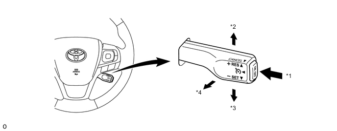
Text in Illustration *1 Main Switch *2 RES/+ *3 SET/- *4 CANCEL
-
-
Combination Meter Assembly (Models with Optitron Type Combination Meter Assembly with TFT Color Multi-information Display)
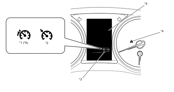
Text in Illustration *A Models with Speed Limiter Control - - *1 Speed Limiter Main Indicator Light *2 Cruise Main Indicator Light *3 Cruise SET Indicator Light *4 Master Warning Light *5 Multi-information Display - -
-
The combination meter assembly illuminates an indicator light or gives an indication on the multi-information display, and sounds a multi buzzer (which is built into the combination meter assembly) in accordance with the respective condition.
Constant Speed Control Mode Condition 


Multi-information Display Multi Buzzer Main Switch On Illuminate - - - - - Mode Set Illuminate Illuminate - - - - Malfunction Occurred - - - Illuminate Check Cruise Control System. Sounds Speed Limiter Control Mode Condition Multi-information Display Multi Buzzer Speed Limiter Main Switch On - - Illuminate - - - Mode Set (Effecting Control) - - Illuminate - 
- Mode Set (Set Speed Exceeded) - - Illuminate - 
Sounds* Malfunction Occurred - - - Illuminate Check Speed Limiter System. Sounds
-
*: When the set speed is exceeded by coast control or override control, the multi buzzer does not sound.
-
-
-
Combination Meter Assembly (Models with Optitron Type Combination Meter Assembly with TFT Monochrome Multi-information Display)
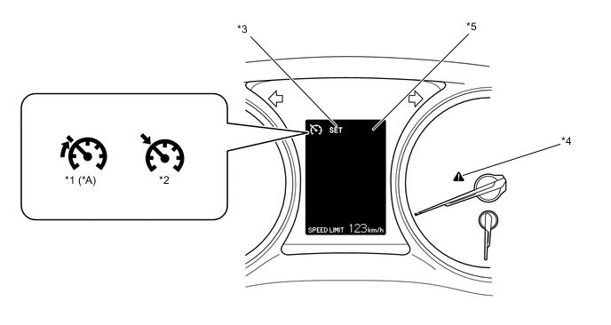
Text in Illustration *A Models with Speed Limiter Control - - *1 Speed Limiter Main Indicator Light *2 Cruise Main Indicator Light *3 Cruise SET Indicator Light *4 Master Warning Light *5 Multi-information Display - -
-
The combination meter assembly illuminates an indicator light or gives an indication on the multi-information display, and sounds a multi buzzer (which is built into the combination meter assembly) in accordance with the respective condition.
Constant Speed Control Mode Condition Multi-information Display Multi Buzzer Main Switch On Illuminate - - - - - Mode Set Illuminate Illuminate - - - - Malfunction Occurred - - - Illuminate CHECK CRUISE CONTROL SYSTEM. Sounds Speed Limiter Control Mode Condition Multi-information Display Multi Buzzer Speed Limiter Main Switch On - - Illuminate - - - Mode Set (Effecting Control) - - Illuminate - 
- Mode Set (Set Speed Exceeded) - - Illuminate - 
Sounds* Malfunction Occurred - - - Illuminate CHECK SPEED LIMITER SYSTEM. Sounds
-
*: When the set speed is exceeded by coast control or override control, the multi buzzer does not sound.
-
-
-
-
DIAGNOSIS
-
If a malfunction occurs in the cruise control system, the ECM cancels the cruise control system. The ECM turns off the cruise main indicator light or the speed limiter main indicator light to inform the driver of a malfunction. Furthermore, the ECM displays a warning message on the multi-information display. At this time, the ECM memorizes the malfunction in the form of a 5-digit Diagnostic Trouble Code (DTC). For details of the DTC, refer to the Repair Manual.
-