LIGHTING SYSTEM
-
FUNCTION OF MAIN COMPONENTS
-
Daytime Running Light System
Component Function Main Body ECU (Instrument Panel Junction Block Assembly) The main body ECU (instrument panel junction block assembly) receives various signals and illuminates the daytime running light. Headlight Dimmer Switch Assembly Light Control Switch The light control switch outputs a light control signal and transmits it to the main body ECU (instrument panel junction block assembly). ECM The ECM outputs an engine speed signal and transmits it to the main body ECU (instrument panel junction block assembly). Electric Parking Brake ECU Transmits the parking brake operation signal to the main body ECU (instrument panel junction block assembly). -
Automatic Light Control System
Component Function Main Body ECU (Instrument Panel Junction Block Assembly) The main body ECU (instrument panel junction block assembly) receives various signals and illuminates the headlights, taillights, clearance lights, and license plate lights. Headlight Dimmer Switch Assembly Light Control Switch The light control switch transmits an AUTO position signal to the main body ECU (instrument panel junction block assembly). Rain Sensor The rain sensor detects the ambient light level. -
LED Headlight System
Component Function Main Body ECU (Instrument Panel Junction Block Assembly) The main body ECU (instrument panel junction block assembly) receives the HEAD position signal and transmits a signal to the light control ECU. Headlight Dimmer Switch Assembly Light Control Switch The light control switch transmits a HEAD position signal to the main body ECU (instrument panel junction block assembly). Headlight Unit LED Driver Module
(Light Control ECU)
The LED driver module (light control ECU) illuminates the LED used as a light source for the low beam headlights and high beam headlights. Combination Meter Assembly Multi-information Display If the system malfunctions, the meter ECU alerts the driver by displaying the warning message. -
Automatic Headlight Beam Level Control System (Static Control Type)
Component Function Headlight Leveling ECU Assembly The headlight leveling ECU assembly receives various signals, calculates the target lighting angle, and actuates the headlight leveling motor. Headlight Unit Headlight Leveling Motor
-
Based on the signals received from the headlight leveling ECU assembly, the motors move the projector unit in the headlight units.
-
Uses a step motor to precisely regulate the angle of the projector units.
Rear Height Control Sensor Sub-assembly Detects the height of the vehicle. Skid Control ECU Transmits the speed sensor signal to the headlight leveling ECU assembly. ECM Transmits the engine running status signal to the headlight leveling ECU assembly. Main Body ECU (Instrument Panel Junction Block Assembly) Transmits the headlight status signal. Combination Meter Assembly Multi-information Display If the system malfunctions, the meter ECU alerts the driver by displaying the warning message in accordance with the signal from the headlight leveling ECU assembly. -
-
Automatic Headlight Beam Level Control System (Dynamic Control Type)
Component Function Headlight Swivel ECU Assembly The headlight swivel ECU assembly receives various signals, calculates the target lighting angle, and actuates the headlight swivel motor. Headlight Unit Headlight Swivel Motor Based on the signals received from the headlight swivel ECU assembly, the motors move the projector unit in the headlight units. Rear Height Control Sensor sub-assembly Detects the height of the vehicle. Skid Control ECU Transmits the speed sensor signal to the headlight swivel ECU assembly. ECM Transmits the engine running status signal to the headlight swivel ECU assembly. Main Body ECU (Instrument Panel Junction Block Assembly) Transmits the headlight status signal. Combination Meter Assembly Multi-information Display If the system malfunctions, the meter ECU alerts the driver by displaying the warning message in accordance with the signal from the headlight swivel ECU assembly. -
Intelligent AFS
Component Function Headlight Swivel ECU Assembly The headlight swivel ECU assembly receives various signals, calculates the target lighting angle, and actuates the headlight swivel motor. Headlight Unit Headlight Swivel Motor
-
Driven by the headlight swivel ECU assembly, the motor moves the low beam left or right to the angle calculated by the headlight swivel ECU assembly.
-
A step motor is used for the headlight swivel motor. The headlight swivel ECU assembly determines the low beam angle based on the number of steps (position) of the step motor.
Steering Sensor Detects the steering angle and direction and outputs this signal to the headlight swivel ECU assembly. Skid Control ECU Transmits the speed sensor signal to the headlight swivel ECU assembly. ECM Transmits the engine running status signal to the headlight swivel ECU assembly. Main Body ECU (Instrument Panel Junction Block Assembly) Transmits the headlight status signal. Combination Meter Assembly Multi-information Display
-
If the system malfunctions, the meter ECU alerts the driver by displaying the warning message in accordance with the signal from the headlight swivel ECU assembly.
-
Changes the on/off status of the intelligent AFS by operating the multi-information display.
-
-
Emergency Brake Signal
Component Function Skid Control ECU Manages signals from each sensor and requests the emergency brake signal operation signal from the combination meter assembly. Speed Sensors Detects the wheel speed of each of the 4 wheels. Stop Light Switch Assembly Detects the brake pedal depressing signal. Hazard Warning Signal Switch Assembly Sends the operation signal of the hazard warning light to the combination meter assembly. Hazard Warning Light Blinks when a signal is received from the hazard warning signal switch assembly. Head Light Assembly Hazard Warning Signal Light Blinks when a signal is received from the combination meter assembly. Side Turn Signal Light Assembly Rear Combination Light Assembly -
Automatic High Beam (AHB) system
Component Function Automatic High Beam Sensor (Pre-crash Safety City Sensor) The automatic high beam sensor determines when to turn the high beams on and off after identifying the lights of oncoming vehicles, preceding vehicles and other lights from the picture information of its camera sensor. Then, the sensor sends high beam request signals to the main body ECU via the CAN communication. Main Body ECU (Instrument Panel Junction Block Assembly)
-
The main body ECU receives an AUTO on signal and high beam position signal from the headlight dimmer switch assembly.
-
The main body ECU receives high beam request signals from the automatic high beam sensor, and controls the headlight assembly (headlight solenoid).
Headlight Assembly Headlight Solenoid The headlight solenoid rotates the shade, which is built into projector unit, down to allow use of the lower illumination area, thus increasing the illumination area when the high beam request signal is received. Skid Control ECU The skid control ECU outputs information about the speed of the wheel. This information is used by the automatic high beam control to control switching between the high beams and low beams of the automatic high beam system. Headlight Dimmer Switch Assembly Light Control Switch The light control switch transmits an AUTO position signal to the main body ECU. Dimmer Switch The dimmer switch transmits a high beam position signal to the main body ECU. Automatic Light Control Sensor (Rain Sensor) The automatic light control sensor detects the ambient light level and transmits a signal to the main body ECU via the windshield wiper relay assembly. Airbag ECU Assembly The airbag ECU assembly outputs the yaw rate information. Combination Meter Assembly Automatic High Beam Indicator Light The automatic high beam indicator light illuminates to inform the driver when the automatic high beam system is activated. High Beam Indicator Light The high beam indicator light illuminates to inform the driver when the high beams are on. Multi-information Display If the system malfunctions, the meter ECU alerts the driver by displaying the warning message in accordance with the signal from the main body ECU. -
-
Cornering Light System
Component Function Main Body ECU (Instrument Panel Junction Block Assembly) Receives signals from each ECU and sensor and illuminates the cornering lights (front fog light assembly). Headlight Dimmer Light Control Switch The light control switch transmits an AUTO position signal to the main body ECU. Turn Signal Light Switch The turn signal light switch transmits a turn signal switch position signal to the combination meter assembly. ECM Transmits the shift position signal to the main body ECU. Combination Meter Assembly Transmits the turn signal light operation signals to the main body ECU. Steering Sensor Detects the steering angle position and transmits it to the main body ECU.
-
-
OPERATING CONDITION
-
Daytime Running Light System
-
Daytime running light system is enabled when the conditions given below are met:
Condition Ignition switch (engine switch*) is ON. Light control switch OFF or AUTO position (when taillight is not being controlled by the automatic light control). Engine is running. Electric parking brake is release.
-
*: Models with entry and start system
-
-
-
Intelligent AFS
-
Low Speed Control
-
The headlight swivel ECU assembly performs the low speed control when all of the following conditions are met:
Condition Engine is running. Vehicle is moving forward at a speed of 10 km/h (6 mph) or more. Steering angle is 6° or more. Headlight is operating in low beam. Intelligent AFS is on.
-
-
Medium-to-high Speed Control
-
The headlight swivel ECU assembly performs the medium-to-high speed control when all of the following conditions are met:
Condition Engine is running. Vehicle is moving forward at a speed of 30 km/h (19 mph) or more. Steering angle is 7.5° or more. Headlight is operating in low beam. Intelligent AFS is on.
-
-
-
Automatic High Beam System
-
Automatic high beam system is enabled when the following conditions are met:
Function Operation Condition Active When all of the following conditions are met, the automatic high beam system is activated and the automatic high beam indicator light turns on:
-
The ignition switch (engine switch*) is on (IG).
-
The light control switch (headlight dimmer switch assembly) is in the AUTO position and the low beam headlights are on.
-
The dimmer switch (headlight dimmer switch assembly) is in the high beam position.
-
The shift lever is in any position other than R.
High Beams On When all of the following conditions are met, the automatic high beam system turns on the high beams after a short delay:
-
Vehicle speed is more than approximately 30 km/h (19 mph).
-
The area in front of the vehicle is dark.
-
No oncoming vehicles are present with the headlights on.
-
No preceding vehicles are present with the taillights on.
-
Few streetlights are present along the street ahead.
High Beams Off When any of the following conditions is met, the automatic high beam system turns off the high beams after a short delay:
-
Vehicle speed is less than approximately 30 km/h (19 mph).
-
The area in front of the vehicle is not dark.
-
An oncoming vehicle with headlights on is detected.
-
A preceding vehicle with taillights on is detected.
-
Several streetlights are present along the street ahead.
-
*: Models with entry and start system
-
-
-
-
SYSTEM CONTROL
-
Intelligent AFS
-
Low Speed Control
-
The headlight swivel ECU assembly calculates the swivel angle from the steering angle and drives the headlight swivel motor on the side facing into the turn to illuminate the road ahead during cornering.
Driving Condition Headlight Unit Left Right LHD Right Turn 0° to 15° to Right 0° to 10° to Right Left Turn 0° to 15° to Left 0° to 10° to Left RHD Right Turn 0° to 10° to Right 0° to 15° to Right Left Turn 0° to 10° to Left 0° to 15° to Left
-
-
Medium-to-high Speed Control
-
Based on the steering angle and vehicle speed, the headlight swivel ECU assembly calculates the swivel angle of the low beam headlights so that the headlights can illuminate the position that the vehicle will reach after 3 seconds, and drives both headlight swivel motors to illuminate the road ahead during cornering.
Driving Condition Headlight Unit Left Right LHD Right Turn 0° Fixed 0° to 15° to Right Left Turn 0° to 10° to Left 0° Fixed RHD Right Turn 0° Fixed 0° to 10° to Right Left Turn 0° to 15° to Left 0° Fixed
-
-
Initial Set Control
-
When the engine is started, the headlight swivel ECU assembly drives the headlight swivel motor, moves the projector headlight to the operation limit in the direction toward the vehicle center and then returns it to the proper position. The headlight swivel ECU assembly thus assesses the position of the headlight for reference control.
-
-
-
Automatic High Beam (AHB) System
-
When passing an oncoming vehicle:
-
The automatic high beam system turns off the high beams before an oncoming vehicle comes within approximately 800 m (2625 ft.).
-
When an oncoming vehicle passes out of the camera sensor range, the automatic high beam system turns the high beams on after a short delay.
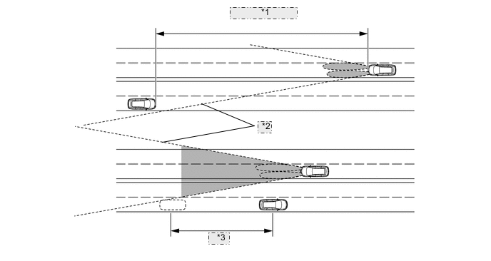
*1 800 m (2625 ft.) *2 Camera Sensor Angle *3 Delay Tech Tips
-
The detection distance varies depending on detected objects.
-
The timing of turning on and off the high beams varies depending on the intensity of oncoming (and preceding) vehicle lights.
-
-
-
When passing a preceding vehicle:
-
When approaching a preceding vehicle, the automatic high beam system turns off the high beams approximately 600 m (1969 ft.) before reaching it.
-
When a preceding vehicle passes out of the camera sensor range, the automatic high beam system turns the high beams on after a short delay.
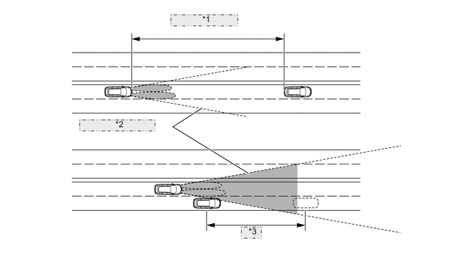
*1 600 m (1969 ft.) *2 Camera Sensor Angle *3 Delay Tech Tips
The timing of turning on and off the high beams varies depending on the intensity of the preceding vehicle lights.
-
-
-
Cornering Light System
-
Cornering lights are provided to increase the distribution of light to the front, sides and top of the vehicle when turning left, right and driving in reverse, improving pedestrian visibility in consideration of safety.
-
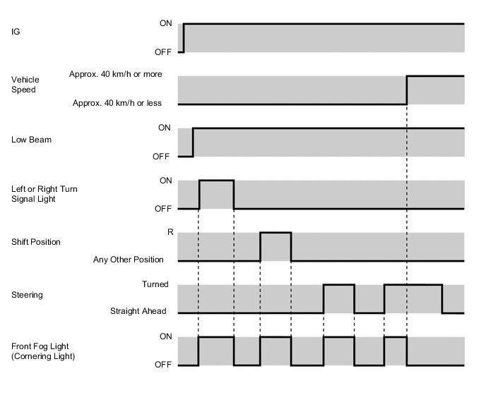
When any of the following conditions is met with the ignition switch (engine switch*) on (IG), low beams illuminated and vehicle speed at approximately 40 km/h or less, the cornering lights (front fog lights) illuminate.
-
Left or right turn signal switch is turned on.
-
Steering wheel is turned to left or right.
-
Shift position is R. (Both side of the cornering lights are illuminated.)
-
-
When the above conditions are no longer met while the cornering lights are illuminated, the cornering lights turn off.
Tech Tips
*: Models with entry and start system
-
-
-
FUNCTION
-
Daytime Running Light System
-
The daytime running light system is controlled by the main body ECU (instrument panel junction block assembly). The main body ECU (instrument panel junction block assembly) illuminates the daytime running light.
-
-
Automatic Light Control System
-
When the light control switch is in the AUTO position, the rain sensor detects the ambient light level and automatically turns the headlights, taillights, clearance lights, and license plate lights on or off accordingly.
-
This system is controlled by the main body ECU (instrument panel junction block assembly).
-
-
Light Automatic Turn-off System
-
The light automatic turn-off system is controlled by the main body ECU (instrument panel junction block assembly).
-
This system has the following functions:
Switch Position Outline TAIL HEAD AUTO - - ○ While the lights (headlight, fog light assembly*1, rear fog light*2, and taillight) are turned on, this system automatically turns them off when the ignition switch (engine switch*3) is turned off. ○ ○ - While the lights (headlights, fog light assembly*1, rear fog light*2, and taillights) are turned on, this system automatically turns off only the headlights and the fog light assembly when the ignition switch (engine switch*3) is turned off.
-
○: Equipped
-
-: Not equipped
-
*1: Models with fog light assembly
-
*2: Models with rear fog light
-
*3: Models with entry and start system
-
-
-
LED Headlight System
-
The LED driver module (light control ECU) illuminates the LED used as a light source for the headlights. When the headlights are illuminated, a constant current flows to the LED to instantly stabilize the headlights. Also, changes in the LED current due to fluctuations in the voltage are reduced to prevent the lights from flickering.
-
-
Automatic Headlight Beam Level Control System (Dynamic Control Type)
-
The automatic headlight beam level control system mainly consists of the headlight swivel ECU assembly, rear height control sensor sub-assembly and 2 headlight swivel motors.
-
The headlight swivel ECU assembly calculates changes in the vehicle posture based on the signals from the rear height control sensor sub-assembly.
-
Following this, the ECU controls the headlight swivel motor based on this information, in order to change the projector unit angle.
-
Initial Set Control
-
When the engine is started, the headlight swivel ECU assembly drives the headlight swivel motor, moves the projector units to the lower limit position and returns it to the proper position. The headlight swivel ECU assembly thus assesses the position of the headlight for reference control.
-
-
-
Automatic Headlight Beam Level Control System (Static Control Type)
-
The automatic headlight beam level control system mainly consists of the headlight leveling ECU assembly, rear height control sensor sub-assembly and 2 headlight leveling motors.
-
The headlight leveling ECU assembly calculates changes in the vehicle posture based on the signals from the rear height control sensor sub-assembly.
-
Following this, the ECU controls the headlight leveling motor based on this information, in order to change the projector unit angle.
-
Initial Set Control
-
When the engine is started, the headlight leveling ECU assembly drives the headlight leveling motor, moves the projector units to the lower limit position and returns it to the proper position. The headlight leveling ECU assembly thus assesses the position of the headlight for reference control.
-
-
-
Follow Me Home Function System
-
The follow me home function system is controlled by the main body ECU.
-
When approximately 30 seconds elapse after all of the following conditions are met, the low beam headlights turn off:
-
The ignition switch (engine switch*) is off.
-
The headlight dimmer switch assembly is in the AUTO position or off position.
-
The headlight dimmer switch assembly is in the pass position, then neutral position.
-
*: Models with entry and start system
-
-
-
-
OPERATION
-
Bi-function
-
If the low beam is selected, the lower illumination area of the halogen bulb is blocked by a shade and only the upper illumination area is used.
-
If the high beam is selected, the headlight solenoid rotates the shade down to allow use of the lower illumination area, thus increasing the illumination area and improving visibility when the high beam is selected.
-
The bi-function is activated by the main body ECU (instrument panel junction block assembly). The main body ECU (instrument panel junction block assembly) receives a signal to turn on the high beams and activates the built-in headlight solenoid to slide the shade down.
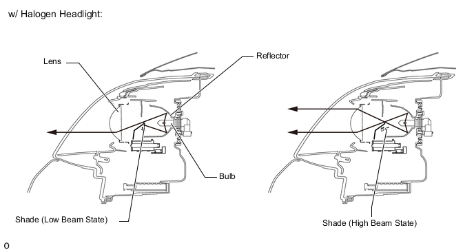
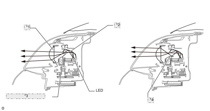
w/ LED Headlight *1 Lens *2 Reflector *3 Shade (Low Beam State) *4 Shade (High Beam State)
-
-
Lightguide Technology
-
Headlight Lightguide
-
The lightguides are used in the clearance lights and the daytime running lights.
-
The lightguides reflect the light of the LEDs with their 'slits'.
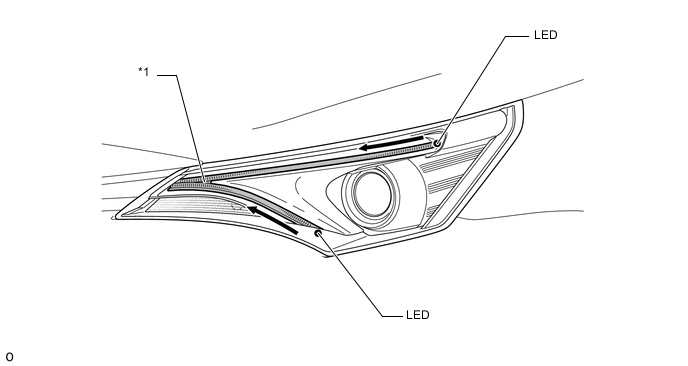
*1 Lightguide -
-
Rear Combination Light Lightguide
-
Tail lightguides are used in the taillights.
-
The tail lightguide reflects the light of the LEDs with their 'slits'.
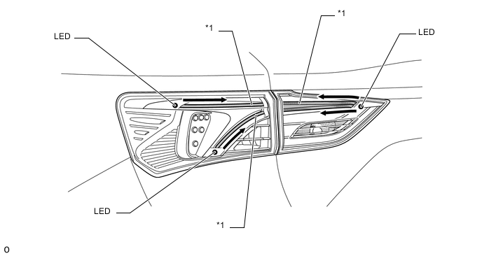
*1 Lightguide -
-
-
Emergency Brake Signal
-
The operating and ending conditions for the emergency brake signal are listed below. When the emergency brake signal operates, the combination meter assembly blinks the hazard warning lights. When the emergency brake signal ends, the combination meter assembly ends the blinking of the hazard warning lights.
Emergency Brake Signal Operating Condition Activates when all of the following conditions are satisfied:
-
The vehicle speed is 55 km/h (34 mph) or more.
-
The system judges from a depression of the brake pedal and a drop in vehicle speed that emergency braking is occurring.
Emergency Brake Signal Ending Condition Stops the operation when any of the following conditions is met:
-
The system judges from the vehicle's deceleration that no emergency braking is occurring.
-
The hazard warning light is blinking.
-
The brake pedal is released.
-
-
-
-
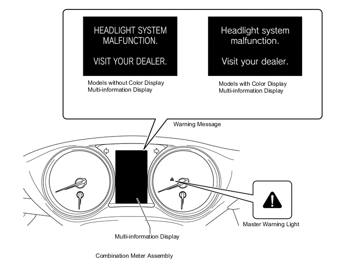
FAIL-SAFE
-
When the following fail-safe is performed, the combination meter assembly (multi-information display) displays the warning message, illuminates the master warning light and sounds the multi buzzer to warn the driver.
-
LED Headlight System
-
If the LED driver module (light control ECU) detects a malfunction in the LED headlight system, the LED driver module performs the fail-safe operation. At the same time, the Diagnostic Trouble Codes (DTCs) are stored in the main body ECU. The DTCs can be read using the service tool. For details, refer to the Repair Manual.
-
-
Automatic Headlight Beam Level Control System (Dynamic Control Type)
-
If the headlight swivel ECU assembly detects a malfunction in the automatic headlight beam level control system, the headlight swivel ECU assembly performs the fail-safe operation. At the same time, the Diagnostic Trouble Codes (DTCs) are stored in memory. The DTCs can be read using the service tool. For details, refer to the Repair Manual.
-
-
Automatic Headlight Beam Level Control System (Static Control Type)
-
If the headlight leveling ECU assembly detects a malfunction in the automatic headlight beam level control system, the headlight leveling ECU assembly performs the fail-safe operation. At the same time, the Diagnostic Trouble Codes (DTCs) are stored in memory. The DTCs can be read using the service tool. For details, refer to the Repair Manual.
-
-
Intelligent AFS System
-
If the headlight swivel ECU assembly detects a malfunction in the intelligent AFS system, the headlight swivel ECU assembly performs the fail-safe operation. At the same time, the Diagnostic Trouble Codes (DTCs) are stored in memory. The DTCs can be read using the service tool. For details, refer to the Repair Manual.
-
-