CVT SYSTEM
-
FUNCTION OF MAIN COMPONENTS
-
The main components of the K114 CVT are as follows:
Component Function CVT Assembly Shift Solenoid Valve SC Used to switch control of the shift solenoid valve SLU between forward and reverse clutch control. Shift Solenoid Valve SL Used to switch control of the shift solenoid valve SLU during lock-up clutch control. Shift Solenoid Valve SLU Performs forward and reverse clutch control or lock-up clutch control depending on the state of the shift solenoid valves SC and SL. Shift Solenoid Valve SLP Controls the oil pressure of the primary pulley in accordance with the vehicle speed and accelerator pedal opening angle to control a speed ratio. Shift Solenoid Valve SLS Controls the oil pressure of the secondary pulley in accordance with the input shaft torque to control belt clamping force. Transmission Revolution Sensor (NIN) Detects the primary pulley speed (input speed). Transmission Revolution Sensor (NOUT) Detects the secondary pulley speed (output speed). Transmission Revolution Sensor (NT) Detects the turbine speed of the torque converter. CVT Fluid Temperature Sensor Detects the CVT fluid temperature. Oil Pressure Sensor Detects the steel belt clamping pressure. Crank Position Sensor Detects the engine speed. Throttle Position Sensor Detects the opening angle of the throttle valve. Accelerator Pedal Position Sensor Detects the amount of pedal effort applied to the accelerator pedal. E.F.I. Engine Coolant Temperature Sensor Detects the engine coolant temperature. Yaw Rate Sensor
-
Detects the vehicle's yaw rate.
-
Detects the vehicle's longitudinal and lateral acceleration and deceleration.
Stop Light Switch Assembly Detects the brake pedal depressing signal. Park/Neutral Position Switch Assembly Detects the shift lever position. Transmission Control Switch
-
Detects that the shift lever is in M.
-
Detects the driver's shift-up and shift-down operations when the shift lever is in M.
Shift Paddle Switch (Transmission Shift Switch Assembly)*
-
Detects the driver's shift-up and shift-down operations in 7-speed sport sequential shiftmatic mode.
-
Operating this switch when the shift lever is in D changes the mode temporarily to 7-speed sport sequential shiftmatic mode.
Pattern Select Switch Assembly Turns the SPORT mode on and off. ECM Drives each shift solenoid valve based on signals from each sensor and switch and optimally controls the CVT. Air Conditioning Amplifier Assembly Transmits the operating state of the air conditioning system to the ECM. Combination Meter Assembly Shift Position and Shift Range Indicator Indicates the shift lever position and shift range. SPORT Mode Indicator Illuminates when the SPORT mode switch is pressed and informs the driver that SPORT mode is active. MIL Illuminates or blinks to alert the driver that the ECM has detected a malfunction. Multi-information Display Displays a message to warn the driver if the CVT fluid reaches a high temperature. Master Warning Light Illuminates to warn the driver if the CVT fluid reaches a high temperature. Multi Buzzer Sounds to warn the driver if the CVT fluid reaches a high temperature.
-
*: Models with shift paddle
-
-
-
SYSTEM CONTROL
-
The electronic control system of the K114 CVT consists of the controls listed below.
Control Outline Engine-CVT Integrated Control Coordinates the control of the CVT system and engine control system to ensure both smooth and powerful driving that excels in shift response and fuel economy. Automatic Shift Control (Speed Ratio Control) Controls the primary pulley speed to approach the target input rotation speed calculated based on the information such as the acceleration pedal opening angle, vehicle speed and brake signals. Acceleration Improvement Control Controls the acceleration rate in proportion to the accelerator pedal position, improving the feeling of linear acceleration and expanding the feeling of accelerator pedal input. Deceleration Improvement Control During deceleration, a pulley ratio is determined and high engine speed is maintained, thus ensuring adequate engine braking. Uphill/Downhill Shift Control Restricts upshifts or to provide appropriate engine braking force by using the ECM to determine whether the vehicle is traveling on uphill or downhill. Lock-up Control
Flex Lock-up Control
The ECM sends a current to shift solenoid valve SC and SL, and shift solenoid valve SLU based on the throttle position sensor signal and vehicle speed signal, and engages or disengages the lock-up clutch. 7-speed Sport Sequential Shiftmatic Enables driving in a gear step selected using the shift lever, providing engine braking force appropriate to each gear step. G AI-shift Control Helps to ensure the vehicle proper posture when entering a corner and ensures the driving torque when exiting a corner. -
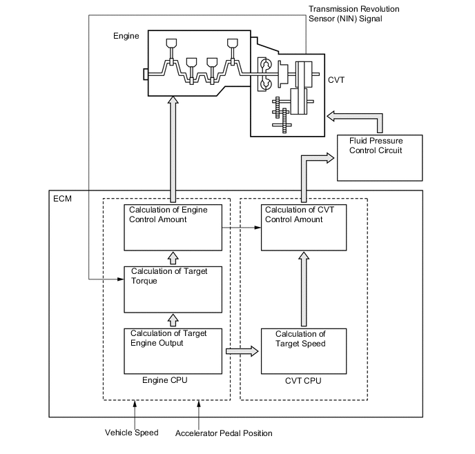
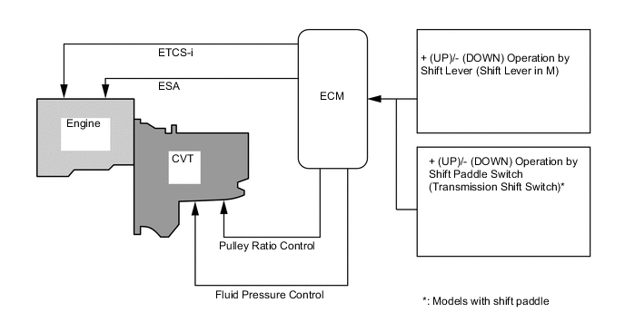
Engine-CVT Integrated Control
-
To apply fine-tuned control in accordance with driving conditions, various signals are exchanged between the engine control system and the CVT system. As a result, both smooth and powerful driving that excels in shift response and fuel economy has been achieved.
-
-
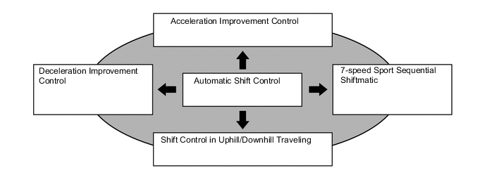
Automatic Shift Control (Speed Ratio Control)
-
The ECM determines the driving conditions through each input signal and selects the optimal control to achieve output which meets the driver's intentions.
-
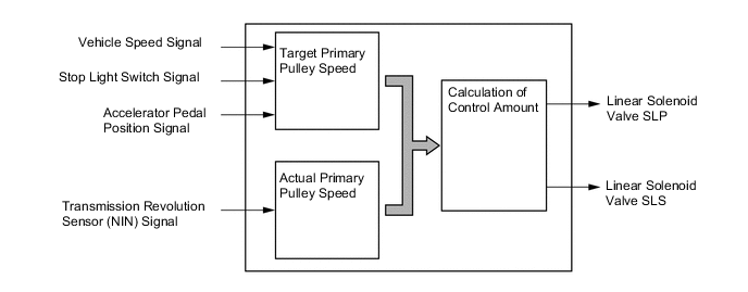
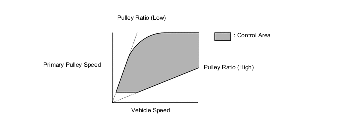
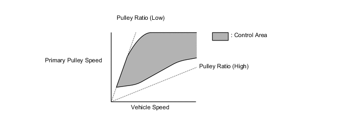
The ECM calculates the target primary pulley speed in accordance with the accelerator pedal position signal, vehicle speed signal, and stop light switch signal, in order to attain an optimal pulley ratio and shifting speed. To adjust the actual primary pulley speed (acquired from the primary speed sensor) to match the target primary pulley speed, the ECM actuates shift solenoid valves SLP and SLS in order to control the pressure of primary pulley and secondary pulley. As a result, the optimal pulley ratio and shifting speed are achieved.
-
When the shift lever is in D, the system effects engine integrated control to optimize fuel economy characteristics and driving performance.
-
When the shift lever is in M, the shift characteristic is as shown below. The system will upshift automatically when the vehicle reaches the set speed during acceleration.
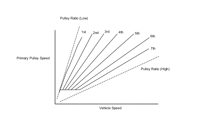
-
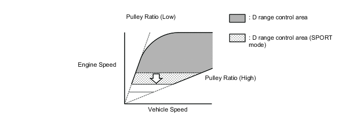
The SPORT mode limits the shift range to the acceleration side and maintains the primary pulley speed at high speeds. This produces a moderate engine braking force and provides an excellent response to accelerator pedal operation.
-
-
Acceleration Improvement Control
-
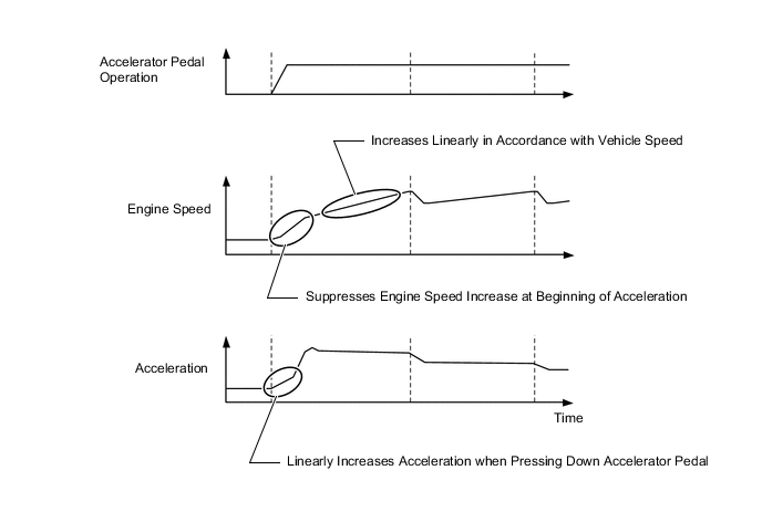
The system determines the driver's acceleration request based on the vehicle speed and the changes in the accelerator pedal position. When the system determines this request, it will change the shift characteristic into one in which the engine speed and vehicle speed increase linearly. This improves the acceleration feeling.
-
In SPORT mode, the control area has been enlarged to improve the direct feeling of acceleration.
-
-
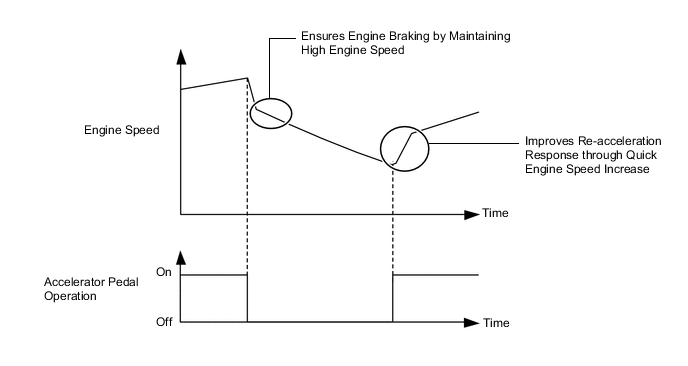
Deceleration Improvement Control
-
During deceleration, a pulley ratio is determined and high engine speed is maintained, thus ensuring adequate engine braking.
-
Engine control, which generates driving force quickly, is conducted during re-acceleration.
-
-
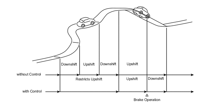
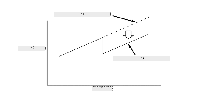
Uphill/Downhill Shift Control
-
The uphill/downhill shift control helps shifting to an optimal speed ratio while driving on a winding uphill or downhill road.
-
When the ECM determines uphill travel, the control restricts upshifting, thus offering smooth driving.
-
If a signal indicating that the driver has operated the brake pedal is input while the ECM detects downhill travel, the control downshifts the speed ratio and generates an optimal engine braking force.
-
The actual acceleration calculated from the vehicle speed signal is compared with the reference acceleration (based on level road travel) stored in the ECM to determine uphill or downhill travel.
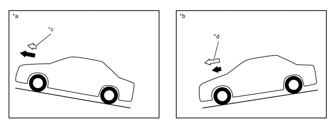
Text in Illustration *a Uphill *b Downhill *c Smaller *d Greater 
Reference Acceleration 
Actual Acceleration
-
-
Lock-up Control
-
The lock-up operation range has been expanded from that of the previous CVT, thus enabling control to start from low speeds.
-
The lock-up operation range during deceleration has been expanded to the low-speed range. This expands the fuel cut range and achieves excellent fuel economy.
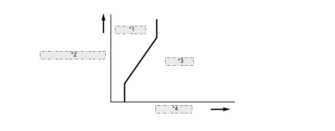
*1 Lock-up Off *2 Throttle Opening Angle *3 Lock-up On *4 Vehicle Speed
-
-
Flex Lock-up Control
-
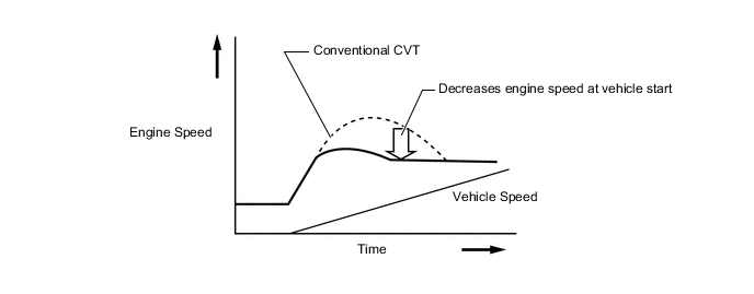
In order to improve the transmission efficiency and also the fuel economy, the shift solenoid valve SLU for lock-up engagement pressure control is employed to deliver flex lock-up control that can provide more precise control than that of the conventional lock-up clutch mechanism.
-
The flex lock-up control consists of flex start control and flex lock-up control at deceleration.
-
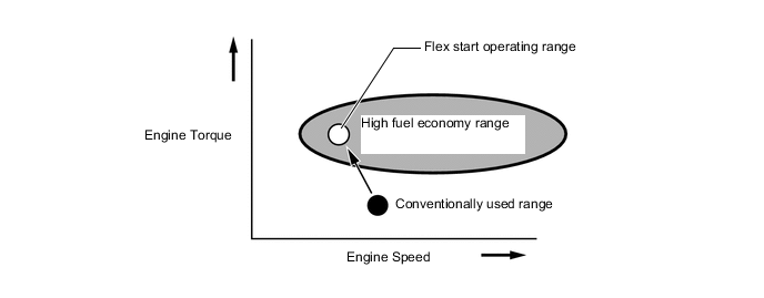
The flex start control aggressively operates the lock-up clutch during start-off to increase the transmission efficiency, as a result, the engine can run in its most efficient operating range.
-
Flex lock-up control during deceleration is used to expand the fuel-cut range. It operates the lock-up clutch over the low vehicle speed range when the vehicle decelerates so that minimal speed difference between the engine speed and turbine speed can be maintained.
-
-
7-speed Sport Sequential Shiftmatic
-
The 7-speed sport sequential shiftmatic is designed to allow the driver to switch the gear step. After moving the shift lever to M, the driver can select the desired gear step by moving the shift lever to "+" (forward) or "-" (backward). On models with a shift paddle, the shift paddle can be used to change the gear step while the driver is holding the steering wheel. Thus, the driver is able to shift gears with a manual-like feel.
Tech Tips
If the shift paddle switch "+ (UP)" or "- (DOWN)" is operated during normal driving mode with the shift lever in D, gear step change operations are temporarily made available.
-
Through the engine-CVT integrated control, the pulley ratio and engine torque which correspond to various shift speeds are finely controlled, thus improving shift response and achieving reduced shifting shock.
-
The shift position and shift range indicator is provided in the shift display of the combination meter assembly. When the shift lever is in P, R, N or D, the shift position is indicated in the shift position and shift range indicator. When the shift lever is in M, or temporary 7-speed sport sequential shiftmatic mode is selected with the shift lever in D, "M" or "D" and the selected shift range is displayed in the shift position and shift range indicator.
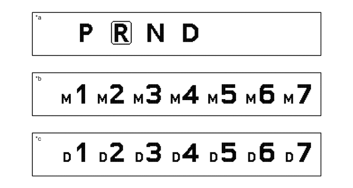
Text in Illustration *a When shift lever is in P, R, N or D *b When shift lever is in M *c During temporary 7-speed sport sequential shiftmatic mode with shift lever in D - - -
In M mode, the CVT automatically upshifts or downshifts under the following conditions:
Condition System Control Engine is under-revving 1 step downshift Engine is over-revving 1 step upshift -
When the vehicle is stopped during temporary 7-speed sport sequential shiftmatic mode, the CVT automatically downshifts to M1.
-
The ECM will restrict the changing of the shift range if it detects a malfunction in the CVT system.
-
If the vehicle speed and engine speed exceeds or goes below a preset level in response to the driver's downshift operation request, changing the shift range will be prohibited. In this case, the buzzer in the combination meter will sound to alert the driver.
-
-
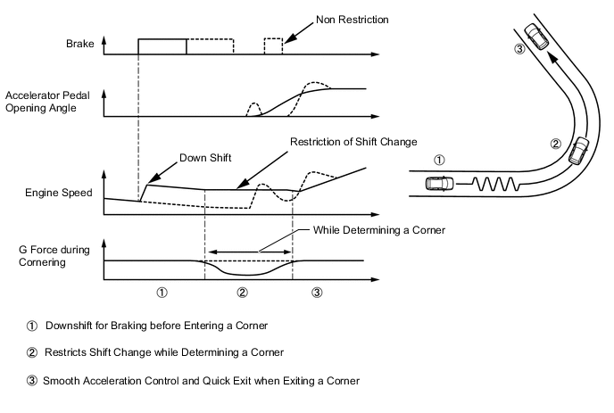
G AI-shift Control
-
G AI-shift control is used. When braking, G AI-shift control performs braking downshift in accordance with the actual braking force, producing appropriate engine braking force. Additionally, while determining a corner condition, G AI-shift control restricts unnecessary shift change and maintains engine speed by detecting a lateral G force, improving acceleration control performance and ensuring the drive torque when exiting a corner.
CAUTION:
-
G AI-shift control is turned on by pressing the SPORT mode switch. When SPORT mode is selected, the SPORT mode indicator in the combination meter assembly illuminates. Pressing the SPORT mode switch again turns SPORT mode off.
-
When the engine is stopped with SPORT mode on, SPORT mode is turned off.
-
When the shift lever is in M or temporary sport sequential shiftmatic mode is selected, shift range change operation due to mode change is not performed.
-
If a malfunction is detected in the CVT system, transmission control is performed in normal mode.
-
-
-
-
FUNCTION
-
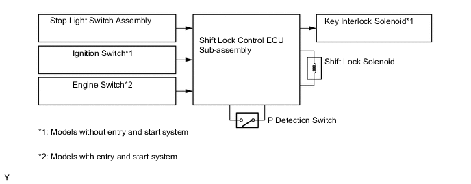
Shift Lock System
-
A shift lock system consisting of a key interlock device* and a shift lock mechanism is used.
-
*: Models without entry and start system
-
-
On the models without the entry and start system, the key interlock device prevents the key from being pulled out after the ignition switch is turned off, unless the shift lever is moved to P. Thus, the driver is urged to park the vehicle with the shift lever in P.
-
The shift lock mechanism prevents the shift lever from being moved to a position other than P, unless the ignition switch is turned to ON, and brake pedal is depressed. This prevents the vehicle from starting off suddenly.
-
A shift lock override button, which manually overrides the shift lock mechanism, is used.
-
-
-
CONSTRUCTION
-
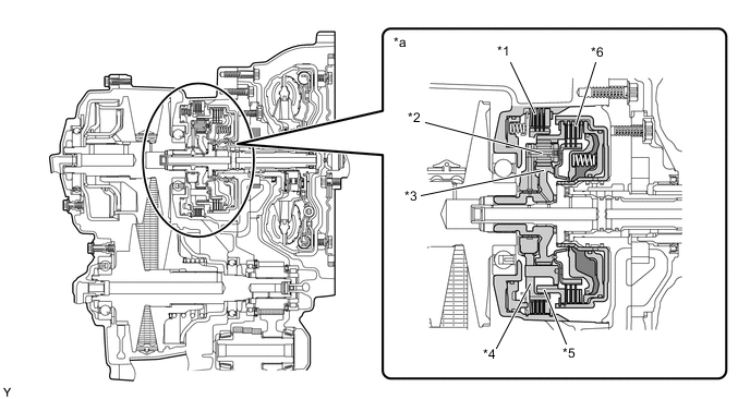
Torque Converter
-
Due to a compact and high-transmission-efficient torque converter, excellent starting and acceleration performance is achieved.
-
A damper structure, which can perform lock-up operation in the low-speed range, is used, achieving low fuel consumption.
-
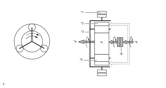
The K114 CVT torque converter assembly utilizes the flex lock-up control mechanism, enabling more meticulous control and achieving further improved fuel efficiency.
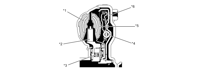
Text in Illustration *1 Pump Impeller *2 Stator *3 1-way Clutch *4 Lock-up Damper *5 Turbine Runner *6 Lock-up Clutch
-
-
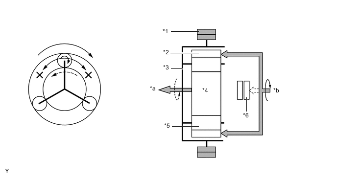
Oil Pump
-
A trochoid gear type oil pump is used.
-
The oil pump is operated by the torque converter. It lubricates the planetary gear units and supplies operating fluid pressure to the hydraulic control.
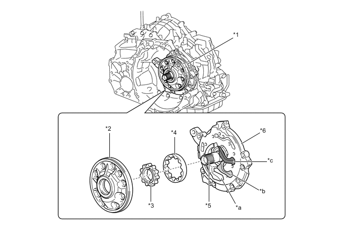
Text in Illustration *1 Oil Pump *2 Oil Pump Body *3 Drive Gear *4 Driven Gear *5 Stator Shaft *6 Oil Pump Cover (Stator Shaft) *a Inlet Port *b Low Pressure Discharge Port *c High Pressure Discharge Port - - -
The oil pump assembly has 1 inlet port and 2 discharge ports.
-
The 2 discharge port oil pump system enables the selection of 2 oil pressure modes in accordance with the engine operating conditions, reducing the required oil pump drive torque.
*1 Drive Torque of Single Discharge Port Oil Pump *2 Drive Torque of Oil Pump *3 Drive Torque of 2 Discharge Port Oil Pump *4 Engine Speed
-
-
Forward/Reverse Switching Unit
-
The forward/reverse switching unit consists of a planetary gear, a forward clutch and a reverse brake.
-
The forward clutch, which operates during forward movement, connects the input shaft to the sun gear.
-
The reverse brake, which operates during reverse movement, keeps the planetary carrier stationary.
Text in Illustration *1 Reverse Brake *2 Pinion *3 Sun Gear *4 Planetary Carrier *5 Ring Gear *6 Forward Clutch *a Forward/Reverse Switching Unit - -
-
-
Pulley and Steel Belt Unit
-
The widths of the grooves of the pulleys are changed through hydraulic control.
-
During acceleration, the operation of the shift solenoid valve SLP increases the oil pressure of the primary pulley, thus decreasing the width of the pulley groove.
-
During deceleration, the operation of the shift solenoid valve SLP decreases the oil pressure of the primary pulley, thus increasing the width of the pulley groove.
-
The secondary pulley is hydraulically controlled by the shift solenoid valve SLS. The shift solenoid valve SLS controls the belt clamping pressure to ensure the proper power transmission efficiency.
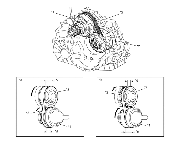
Text in Illustration *1 Secondary Pulley *2 Primary Pulley *3 Steel Belt - - *a Pulley Ratio (Low) *b Pulley Ratio (High) *c Groove Width (Large) *d Groove Width (Small) -
The primary pulley uses a double piston construction, resulting in a compact and lightweight assembly. The 2 chambers generate hydraulic pressure to vary the groove width.
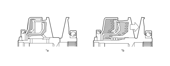
Text in Illustration *a Pulley Ratio (Low) *b Pulley Ratio (High) 
Chamber A 
Chamber B -
The steel belt consists of elements and 2 rows of steel rings. In contrast to chains and V-belts which transmit power through the use of tensile force, this steel belt uses the compressive action (pushing force) of the elements to transmit power.
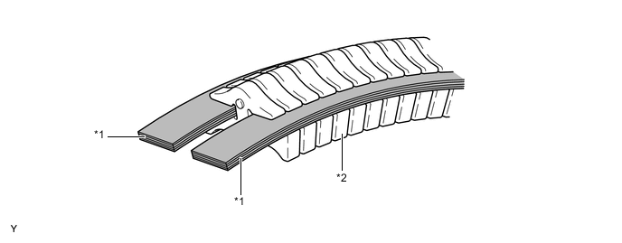
Text in Illustration *1 Steel Ring *2 Element
-
-
Reduction Gear and Differential
-
The reduction gear reduces the speed of the engine torque output through the secondary pulley and transmits it to the differential.
-
The reduction drive gear is supported by 2 independent bearings in order to optimize meshing with the reduction driven gear, resulting in quiet operation.
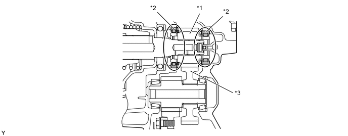
Text in Illustration *1 Reduction Drive Gear *2 Bearing *3 Reduction Driven Gear - - -
A differential preload mechanism, in which the conical spring is located between the side gear and the side gear washer, is used.
-
The load of the conical spring applies a friction force to the sliding area, improving straightline stability and steering stability.
-
Under light load and low differential rotation speeds, due to the friction force of the sliding area, the differential limit torque for the left and right wheels is achieved within the range of the conical spring allowable load. At middle and high load ranges, which are beyond the allowable load of the conical spring, the system performs as an open differential.
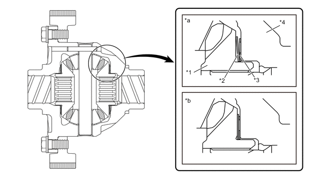
Text in Illustration *1 Side Gear *2 Conical Spring *3 Side Gear Washer *4 Differential Case *a Light Load Range *b Middle and High Load Range 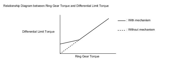
-
-
Transmission Valve Body Assembly
-
The transmission valve body assembly consists of upper and lower valve bodies and 5 shift solenoid valves.
-
The 5 shift solenoid valves are installed in the lower valve body, ensuring serviceability.
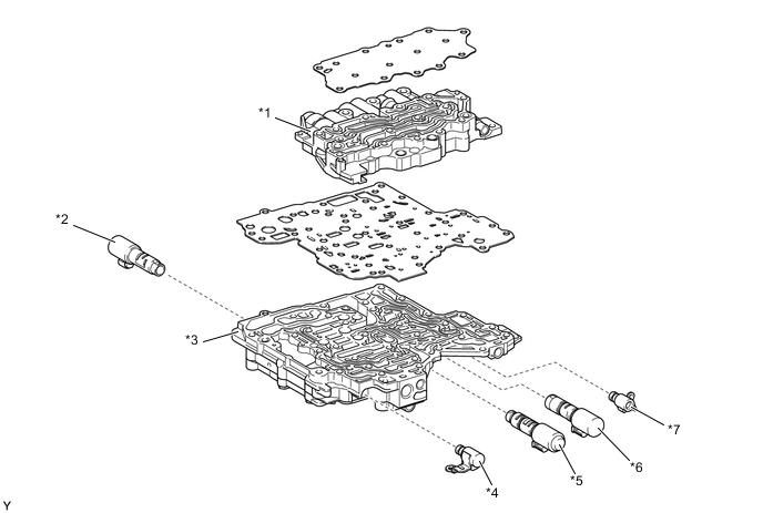
Text in Illustration *1 Upper Valve Body *2 Shift Solenoid Valve SLU *3 Lower Valve Body *4 Shift Solenoid Valve SC *5 Shift Solenoid Valve SLP *6 Shift Solenoid Valve SLS *7 Shift Solenoid Valve SL - - 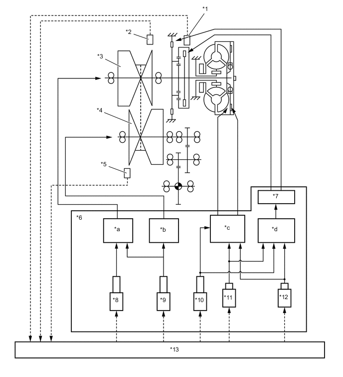
Text in Illustration *1 Transmission Revolution Sensor (NT) *2 Transmission Revolution Sensor (NIN) *3 Primary Pulley *4 Secondary Pulley *5 Transmission Revolution Sensor (NOUT) *6 Valve Body *7 Manual Valve *8 Shift Solenoid Valve SLP *9 Shift Solenoid Valve SLS *10 Shift Solenoid Valve SLU *11 Shift Solenoid Valve SL *12 Shift Solenoid Valve SC *13 ECM - - *a Pulley Ratio Control *b Belt Clamping Pressure Control *c Lock-up Control *d Clutch Pressure Control -
The functions of each shift solenoid valve are outlined in the table below.
Shift Solenoid Valve Type Function Shift Solenoid Valve SC On-off Used to switch control of the shift solenoid valve SLU between forward and reverse clutch control. Shift Solenoid Valve SL On-off Used to switch control of the shift solenoid valve SLU between lock-up clutch control. Shift Solenoid Valve SLS Linear Controls the oil pressure of the secondary pulley. Shift Solenoid Valve SLP Linear Controls the oil pressure of the primary pulley. Shift Solenoid Valve SLU Linear Performs forward and reverse clutch control or lock-up clutch control depending on the state of the shift solenoid valves SC and SL. -
Steel Belt Clamping Force Control
-
To ensure the proper control of the belt clamping pressure necessary for transmitting torque, the system controls the hydraulic pressure applied to the secondary pulley. The transmission valve body assembly is provided with a dedicated hydraulic pressure circuit for belt clamping pressure control. This circuit optimally controls the hydraulic pressure applied to the secondary pulley, thus achieving superior torque transmission performance.
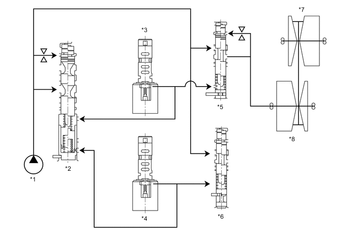
Text in Illustration *1 Oil Pump Assembly *2 Primary Regulator Valve *3 Shift Solenoid Valve SLS *4 Shift Solenoid Valve SLP *5 No. 1 Line Pressure Modulator Valve *6 No. 3 Line Pressure Modulator Valve *7 Primary Pulley *8 Secondary Pulley
-
-
Pulley Ratio Control (Shift Control)
-
Pulley ratio control is performed by controlling the hydraulic pressure applied to the primary pulley in order to provide fine-tuned control and a high level of reliability.
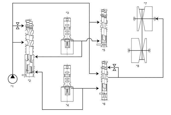
Text in Illustration *1 Oil Pump Assembly *2 Primary Regulator Valve *3 Shift Solenoid Valve SLS *4 Shift Solenoid Valve SLP *5 No. 1 Line Pressure Modulator Valve *6 No. 3 Line Pressure Modulator Valve *7 Primary Pulley *8 Secondary Pulley
-
-
Lock Up Control
-
Lock-up control is performed by controlling the oil pressure of the lock-up clutch. The shift solenoid valve SL and shift solenoid valve SLU are provided to control the lock-up clutch.
-
-
-
Parking Lock Mechanism
-
A parking lock mechanism is used on the secondary pulley. The engagement of the parking lock pawl with the parking lock gear integrated into the secondary pulley locks the transaxle.
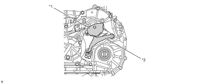
Text in Illustration *1 Parking Lock Gear *2 Parking Lock Pawl
-
-
Park/Neutral Position Switch Assembly
-
The ECM uses the park/neutral position switch assembly to detect the shift lever position.
-
The park/neutral position switch assembly sends P, R, N and D position signals to the ECM. The ECM also sends signals to the combination meter assembly via CAN.
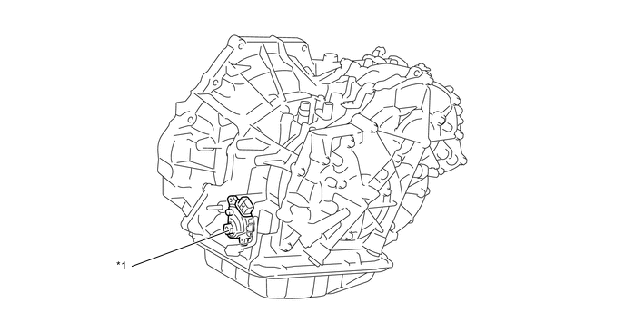
Text in Illustration *1 Park/Neutral Position Switch Assembly - - 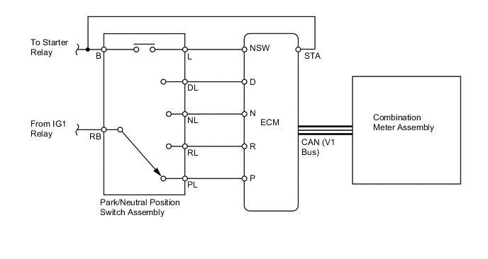
-
-
Transmission Control Switch
-
The transmission control switch is installed in the floor shift lever assembly. This switch sends a signal to the ECM when the shift lever is moved to M and "+" or "-".
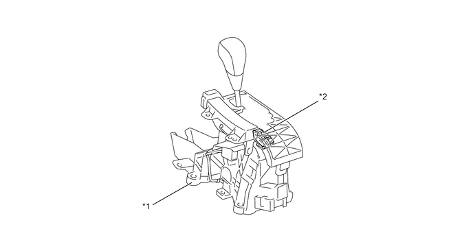
Text in Illustration *1 Floor Shift Lever Assembly *2 Transmission Control Switch 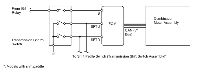
-
-
Shift Paddle Switch (Models with Shift Paddle)
-
The shift paddle switch (transmission shift switch assembly) is installed in the steering wheel. The shift paddle switch (transmission shift switch assembly) detects the operating conditions of the shift paddle "+" (upshift) or "-" (downshift) when the shift lever is in D or M, and sends the SFTU and SFTD signals to the ECM.
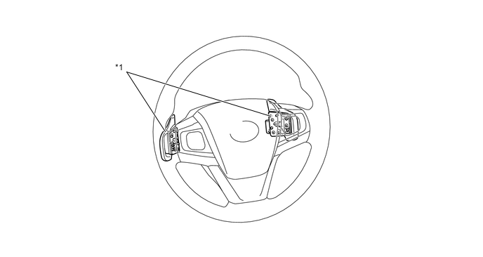
Text in Illustration *1 Shift Paddle Switch (Transmission Shift Switch Assembly) - - 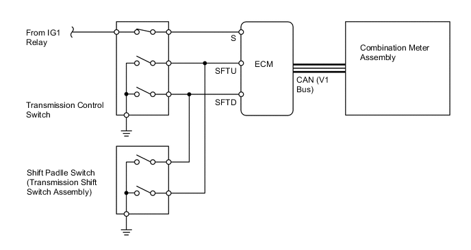
-
-
Transmission Revolution Sensor
-
The functions of each transmission revolution sensor are outlined in the table below:
Transmission Revolution Sensor Type Output Signal Function NIN Pick-up Coil Analog Signal Detects the primary pulley speed from the rotation of the timing rotor on the primary pulley. NOUT Hall High/Low Digital Signal Detects the secondary pulley speed from the rotation of the reduction driven gear. NT Hall High/Low Digital Signal Detects the turbine speed from the rotation of the timing rotor on the forward clutch drum connected to the torque converter turbine runner. 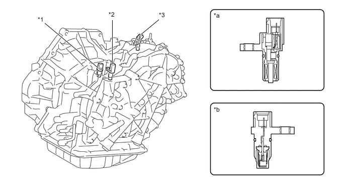
Text in Illustration *1 Transmission Revolution Sensor (NT) *2 Transmission Revolution Sensor (NIN) *3 Transmission Revolution Sensor (NOUT) - - *a Pick-up Coil Type *b Hall IC Type 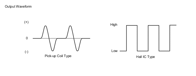
-
-
CVT Fluid Warmer
-
The CVT fluid warmer (transmission oil cooler) uses engine coolant that has been warmed by the engine to warm up the CVT fluid quickly and maintain a high CVT fluid temperature (within limits). Consequently, the friction losses of the CVT are quickly reduced, thus improving fuel economy.
-
After warming up the CVT fluid, the engine coolant continues to flow into the CVT fluid warmer (transmission oil cooler) to cool down the CVT fluid.
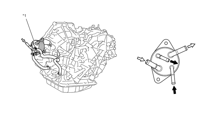
Text in Illustration *1 CVT Fluid Warmer (Transmission Oil Cooler) - - CVT Fluid Flow Engine Coolant Flow
-
-
Shift Control Mechanism
-
A gate type shift lever is used.
-
The shift control mechanism consists of a floor shift lever assembly and a transmission control cable assembly.
-
The shift lock solenoid is built into the floor shift lever assembly.
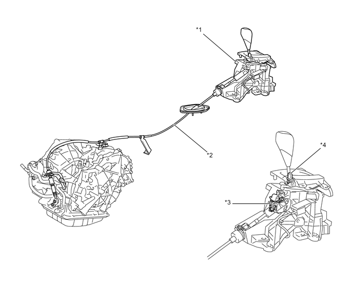
Text in Illustration *1 Floor Shift Lever Assembly *2 Transmission Control Cable Assembly *3 Shift Lock Solenoid *4 Shift Lock Release Button
-
-
-
OPERATION
-
Forward/Reverse Switching Unit
-
When driving forward, the forward clutch is engaged, causing engine torque to be input from the input shaft to the sun gear, and output through the primary pulley.
Text in Illustration *1 Reverse Brake *2 Ring Gear *3 Planetary Carrier *4 Sun Gear *5 Pinion *6 Forward Clutch *a Output *b Input -
When driving in reverse, engine torque is input to the ring gear. Then, the engine torque is input to the sun gear via the pinion (which is held by the reverse brake). Consequently, the gear and primary pulley rotation is reversed.
Text in Illustration *1 Reverse Brake *2 Ring Gear *3 Planetary Carrier *4 Sun Gear *5 Pinion *6 Forward Clutch *a Output *b Input
-
-
Transaxle Power Flow
-
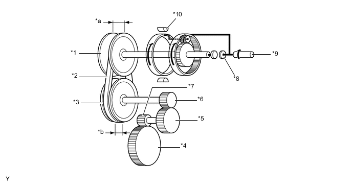
The changing of the pulley ratio is accomplished in a continuously variable manner by varying the widths of the grooves of the primary and secondary pulleys.
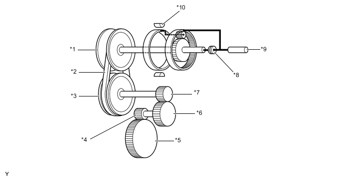
Text in Illustration *1 Primary Pulley *2 Steel Belt *3 Secondary Pulley *4 Differential Drive Pinion *5 Differential Ring Gear *6 Reduction Driven Gear *7 Reduction Drive Gear *8 Forward Clutch *9 Input Shaft *10 Reverse Brake -
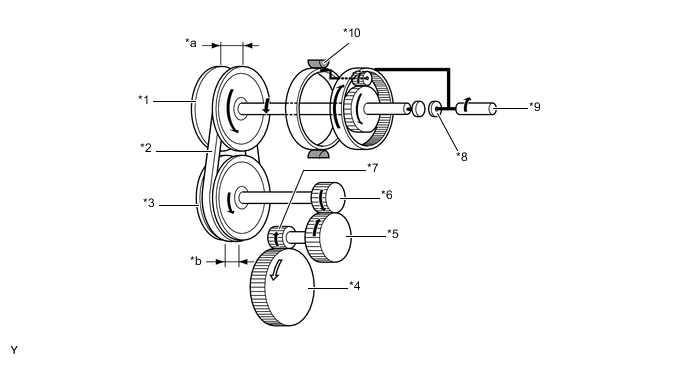
Shift Lever in D (Pulley Ratio Low)
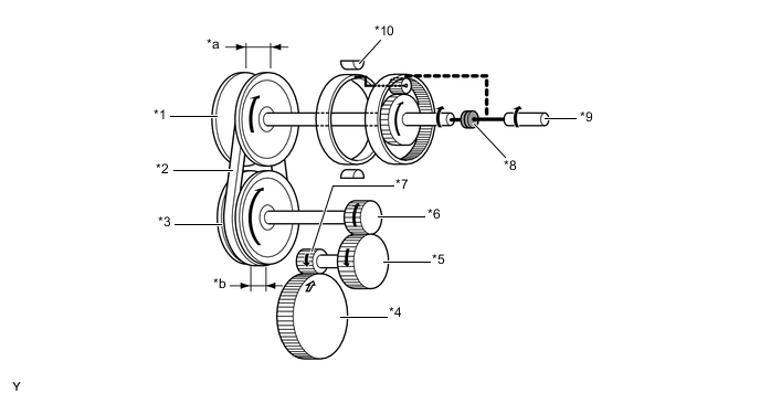
Text in Illustration *1 Primary Pulley *2 Steel Belt *3 Secondary Pulley *4 Differential Ring Gear *5 Reduction Driven Gear *6 Reduction Drive Gear *7 Differential Drive Pinion *8 Forward Clutch (On) *9 Input Shaft *10 Reverse Brake (Off) *a Groove Width (Large) *b Groove Width (Small) -
Shift Lever in D (Pulley Ratio High)
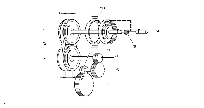
Text in Illustration *1 Primary Pulley *2 Steel Belt *3 Secondary Pulley *4 Differential Ring Gear *5 Reduction Driven Gear *6 Reduction Drive Gear *7 Differential Drive Pinion *8 Forward Clutch (On) *9 Input Shaft *10 Reverse Brake (Off) *a Groove Width (Small) *b Groove Width (Large) -
Shift Lever in N
Text in Illustration *1 Primary Pulley *2 Steel Belt *3 Secondary Pulley *4 Differential Ring Gear *5 Reduction Driven Gear *6 Reduction Drive Gear *7 Differential Drive Pinion *8 Forward Clutch (Off) *9 Input Shaft *10 Reverse Brake (Off) *a Groove Width (Large) *b Groove Width (Small) -
Shift Lever in R
Text in Illustration *1 Primary Pulley *2 Steel Belt *3 Secondary Pulley *4 Differential Ring Gear *5 Reduction Driven Gear *6 Reduction Drive Gear *7 Differential Drive Pinion *8 Forward Clutch (Off) *9 Input Shaft *10 Reverse Brake (On) *a Groove Width (Large) *b Groove Width (Small) -
Shift Lever in M
-
Gear train movement when the shift lever is in M is similar to the one when the shift lever is in D. However, since pulley ratio is adjusted in accordance with driver's shift operation, the driver is able to upshift or downshift with a manual-like feel.
-
-
-
-
FAIL-SAFE
-
This fail-safe function minimizes the loss of operability when an abnormality occurs in a sensor or shift solenoid valve. For details, refer to the Repair Manual.
-
-
DIAGNOSIS
-
When the ECM detects a malfunction, it records the malfunction and information related to the fault. Furthermore, the ECM will illuminate or blink the MIL in the combination meter to inform the driver.
-
At the same time, the Diagnostic Trouble Codes (DTCs) are stored in memory. The DTCs can be read by connecting the Global TechStream (GTS) to the DLC3. For details, refer to the Repair Manual.
-