FUEL SYSTEM
-
OUTLINE
-
A long nozzle type fuel injector assembly is used. This injector has 12 fuel injection holes.
-
A fuel returnless system is used to reduce evaporative emissions.
-
As shown below, the fuel suction with pump and gauge tube assembly is used, which contains the fuel filter, fuel pressure regulator assembly, charcoal canister, fuel sender gauge assembly and fuel pump. This makes it possible to discontinue the return of fuel from the engine area and to prevent temperature rise inside the fuel tank.
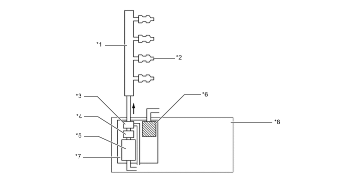
Text in Illustration *1 Fuel Delivery Pipe Sub-assembly *2 Fuel Injector Assembly *3 Fuel Pressure Regulator Assembly *4 Fuel Filter *5 Fuel Pump *6 Charcoal Canister *7 Fuel Suction with Pump and Gauge Tube Assembly *8 Fuel Tank Assembly
-
-
An inner pipe is provided inside the fuel delivery pipe sub-assembly to absorb fuel pulsations.
-
A multiplex layered plastic fuel tank is used.
-
A fuel cut control is used to stop the fuel pump when any of the Supplemental Restraint System (SRS) airbags are deployed.
-
A quick connector is used to connect the fuel pipe with the fuel hose for excellent serviceability.
-