SFI SYSTEM
-
FUNCTION OF MAIN COMPONENTS
-
The main components of the engine control system are as follows:
Component Outline Quantity Function ECM 32-bit 1 The ECM optimally controls the engine control system to suit the operating conditions of the engine in accordance with the signals provided by the sensors. Air Fuel Ratio Sensor (Bank 1, Sensor 1) Type with Heater (Planar Type) 1 Detects the oxygen concentration in the exhaust emission by measuring the electromotive force generated in the sensor itself. Oxygen Sensor (Bank 1, Sensor 2) Type with Heater (Cup Type) 1 Intake Mass Air Flow Meter Sub-assembly Hot-wire Type 1 Uses a built-in hot-wire to directly detect the intake air mass. Intake Air Temperature Sensor Thermistor Type 1 Detects the intake air temperature. E.F.I. Engine Coolant Temperature Sensor Thermistor Type 1 Detects the engine coolant temperature. Crank Position Sensor [Rotor Teeth] Pick-up Coil Type [36 - 2] 1 Detects the engine speed and performs the cylinder identification. No. 1 Crank Position Sensor (Camshaft Position Sensor) [Rotor Teeth] Magnetic Resistance Element (MRE) Type [3] 2 Performs the cylinder identification. Throttle Position Sensor Non-contact Type 1 Detects the throttle valve opening angle. Accelerator Pedal Position Sensor Non-contact Type 1 Detects the amount of pedal effort applied to the accelerator pedal. Knock Control Sensor Built-in Piezoelectric Element Type (Flat Type) 1 Detects an occurrence of engine knocking indirectly from the vibration of the cylinder block caused by the occurrence of engine knocking. E.F.I. Vacuum Sensor Assembly Semiconductor Silicon Chip Type 1
-
Detects the intake manifold pressure.
-
Corrects the fuel injection in accordance with variations in air pressure.
-
Detects the presence of deposits in the intake valve by determining the intake manifold pressure.
Continuously Variable Valve Lift Controller Assembly Built-in EDU 1
-
Includes the EDU and controls the motor in response to signals from the ECM in order to regulate the amount of intake valve lift and the intake valve action angle.
-
The built-in motor position sensor detects the motor position.
-
The built-in action angle sensor detects the position of the actuator in order to confirm the action angle.
Camshaft Timing Oil Control Valve Assembly Solenoid Type 2 Changes the oil passage to the camshaft timing gear assembly (VVT-i controller) in response to signals from the ECM. Throttle Control Motor DC Motor 1 Throttle control motor regulates the opening of the throttle valve in accordance with the signals from the ECM. Fuel Injector Assembly 12-hole Type 4 The fuel injector assembly is an electromagnetically-operated nozzle which injects fuel in accordance with the signals from the ECM. Ignition Coil Assembly Type with Igniter 4 Incorporates an igniter and provides the high level of voltage necessary for ignition in accordance with signals from the ECM. Duty Vacuum Switching Valve (VSV for ACIS) Solenoid Type 1 Controls the actuator for ACIS in accordance with ECM signals. Spark Plug Iridium-tipped Type 4 Sparks a high level of voltage from the ignition coil assembly inside the cylinder. -
-
-
SYSTEM CONTROL
-
The engine control system has the following features. The ECM controls these systems:
System Outline Sequential Multiport Fuel Injection (SFI)
-
An L-type SFI System detects the intake air mass with a hot-wire type intake mass air flow meter sub-assembly.
-
The fuel injection system is a sequential multiport fuel injection system.
Electronic Throttle Control System-intelligent (ETCS-i) Optimally controls the throttle valve opening in accordance with the amount of accelerator pedal effort, the throttle valve opening control request from the ECM, and the condition of the engine and the vehicle. Electronic Spark Advance (ESA) Ignition timing is determined by the ECM based on signals from various sensors. The ECM corrects ignition timing in response to engine knocking. VALVEMATIC Effects coordinate control with the Dual VVT-i in order to control the amount of intake valve lift, and intake and exhaust valve timing. Dual Variable Valve Timing-intelligent (Dual VVT-i) Regulates operation of the intake and exhaust camshafts to ensure an optimal valve timing in accordance with the engine condition. Acoustic Control Induction System (ACIS) The intake air passages are switched in accordance with the engine speed and throttle valve opening angle to provide high performance in all speed ranges. Fuel Pump Control
-
Fuel pump operation is controlled by signals from the ECM.
-
The fuel pump is stopped when any of the Supplemental Restraint System (SRS) airbags are deployed.
Air Fuel Ratio Sensor and Oxygen Sensor Heater Control Maintains the temperature of the air fuel ratio sensor and oxygen sensor at an appropriate level to increase accuracy of detection of the oxygen concentration in the exhaust gas. Engine Immobiliser Prohibits fuel delivery and ignition if an attempt is made to start the engine with an invalid key. Air Conditioning Cut-off Control*1 By turning the air conditioning compressor assembly on or off in accordance with the engine condition, driveability is maintained. Cooling Fan Control The ECM steplessly controls the speed of the fan via the cooling fan ECU in accordance with the engine coolant temperature, vehicle speed, engine speed, and air conditioning conditions*1. As a result, good cooling performance has been achieved. Starter Control*2 Once the engine switch is pushed, this control continues to operate the starter until the engine has started. Diagnosis When the ECM detects a malfunction, the ECM diagnoses and memorizes the failed section. Fail-safe When the ECM detects a malfunction, the ECM stops or controls the engine in accordance with the data already stored in memory.
-
*1: Models with air conditioning
-
*2: Models with entry and start system
-
-
-
FUNCTION
-
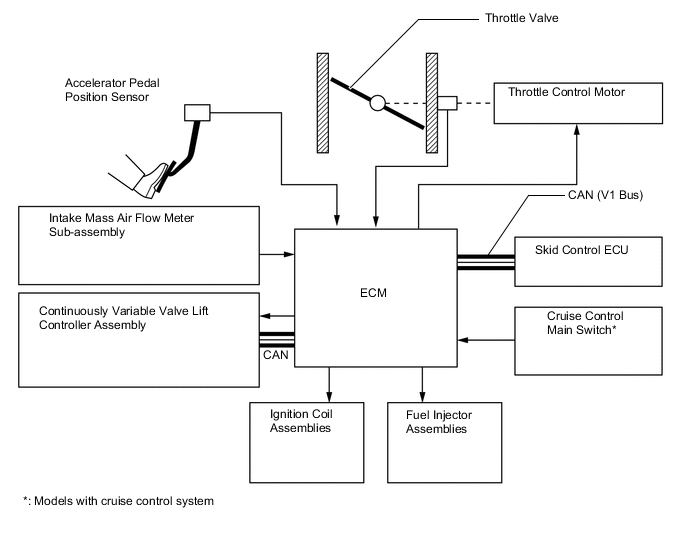
Electronic Throttle Control System-intelligent (ETCS-i)
-
The ETCS-i is used, providing excellent throttle control in all operating ranges. The accelerator cable has been discontinued, and an accelerator pedal position sensor has been provided on the accelerator pedal.
-
In the conventional throttle body, the throttle valve opening is determined invariably by the amount of accelerator pedal effort. In contrast, the ETCS-i uses the ECM to calculate the optimal throttle valve opening that is appropriate for the respective driving condition and uses a throttle control motor to control the opening.
-
The ETCS-i controls the Idle Speed Control (ISC) system, Traction Control (TRC), Vehicle Stability Control (VSC) system and cruise control system*.
-
*: Models with cruise control system
-
-
In case of an abnormal condition, this system switches to the limp mode.
-
The ETCS-i effects coordinate control with the VALVEMATIC.
-
-
VALVEMATIC
-
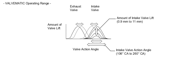
The VALVEMATIC effects coordinate control with the Dual VVT-i. It effects continuously variable control of the amount of intake valve lift, intake valve action angle, and intake valve timing, as well as control of the exhaust valve timing, in accordance with the engine conditions. This results in improved engine performance and better fuel economy.
-
The intake valve action angle varies between 106° CA and 260° CA, and the amount of intake valve lift varies between 0.9 mm (0.0354 in.) and 11 mm (0.433 in.).
-
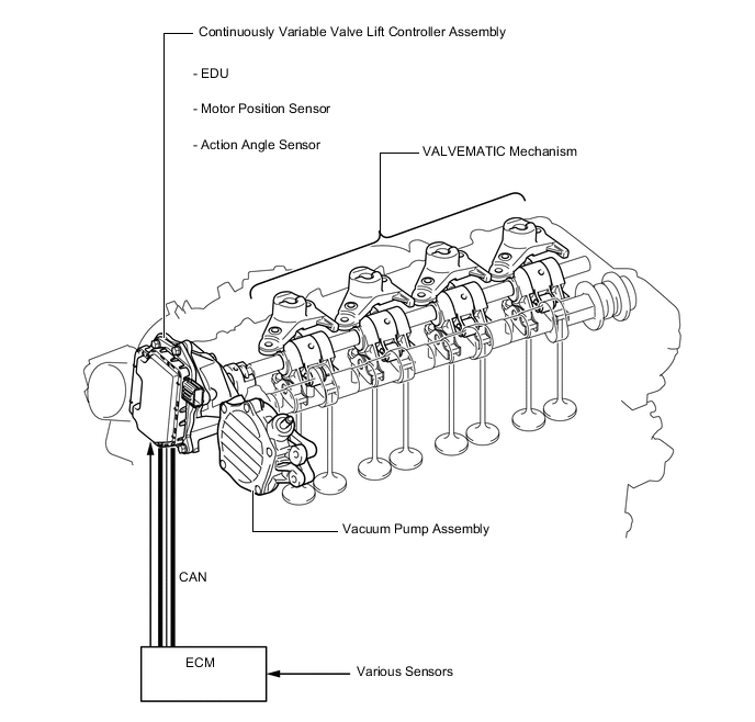
The VALVEMATIC consists of a continuously variable valve lift controller assembly at the actuator and VALVEMATIC mechanism.
-
Along with the use of this system, a vacuum pump assembly is provided in order to provide the proper brake control vacuum.
-
The VALVEMATIC controls the amount of intake valve lift, intake valve action angle, intake valve timing, and exhaust valve timing in order to achieve the following effectiveness.
Condition: Upon Starting/Stopping Engine Operation Valve Timing/Camshaft Position 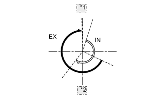
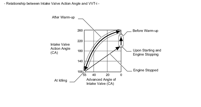
*1 TDC *2 BDC Amount of Valve Lift/Valve Action Angle Intake valve action angle is fixed at 200° CA.* 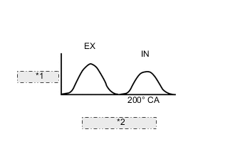
*1 Valve Lift *2 Valve Action Angle Objective Reducing overlap to improve compression ratio Effect Improved startability Tech Tips
*: During cranking, if the ECM determines that the engine has started, the intake valve actionangle moves to 255° CA.
Condition: At First Idling Operation Valve Timing/Camshaft Position 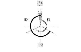
*1 TDC *2 BDC Amount of Valve Lift/Valve Action Angle Intake valve action angle is fixed at 255° CA. 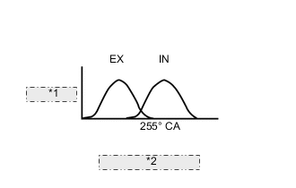
*1 Valve Lift *2 Valve Action Angle Objective Increasing overlap to increase internal EGR Effect Improved emission control Condition: Before Engine Warm-up (Except First Idling) Operation Valve Timing/Camshaft Position 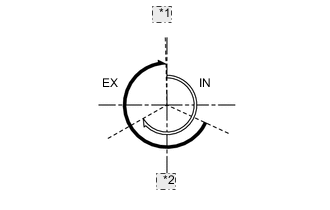
*1 TDC *2 BDC Amount of Valve Lift/Valve Action Angle Intake valve action angle is fixed at 240° CA. 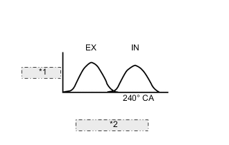
*1 Valve Lift *2 Valve Action Angle Objective Improving intake air charging efficiency Effect
-
Improved output
-
Better fuel economy
Condition: At Light and Medium Load (After Warm-up) Operation Valve Timing/Camshaft Position 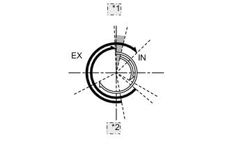
*1 TDC *2 BDC Amount of Valve Lift/Valve Action Angle
-
Effects coordinate control with Dual VVT-i and ETCS-i.
-
Amount of intake valve lift is variable.
-
Intake valve action angle is variable within a range between 106° CA and 245° CA.
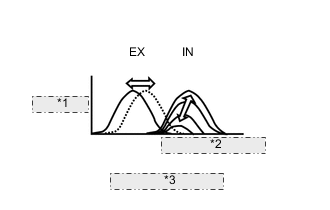
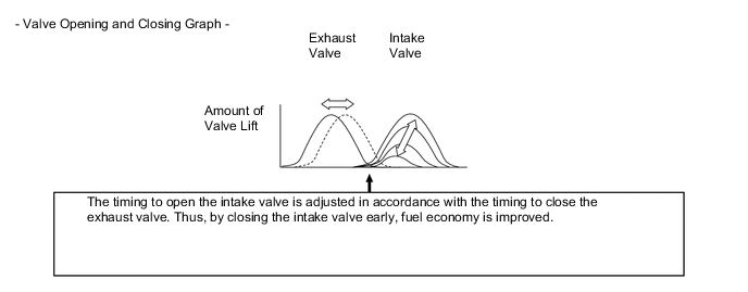
*1 Valve Lift *2 106° CA to 245° CA *3 Valve Action Angle Objective Closing the intake valve early to reduce pumping loss Effect Better fuel economy Condition: At Heavy Load (After Warm-up) Operation Valve Timing/Camshaft Position 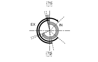
*1 TDC *2 BDC Amount of Valve Lift/Valve Action Angle
-
Effects coordinate control with Dual VVT-i.
-
Amount of intake valve lift is variable.
-
Intake valve action angle is variable within arange between 220° CA and 260° CA.
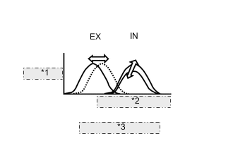
*1 Valve Lift *2 220° CA to 260° CA *3 Valve Action Angle Objective Closing the intake valve late, thus retarding the injection timing, to improve volumetric efficiency Effect
-
Improved output
-
Better fuel economy
-
Reduction of exhaust gas temperature
-
-
-
Dual Variable Valve Timing-intelligent (Dual VVT-i) System
-
The Dual VVT-i system is designed to control the intake and exhaust camshafts. This system effects coordinate control with the VALVEMATIC in order to provide valve timing optimally suited to the engine conditions. This improves torque in all the speed ranges as well as increasing fuel economy, and reducing exhaust emissions.
-
Because the Dual VVT-i of this engine effects coordinate control with the VALVEMATIC, it has a timing advance characteristic that differs from the conventional Dual VVT-i. For details, see VALVEMATIC in Function and Operation.
-
-
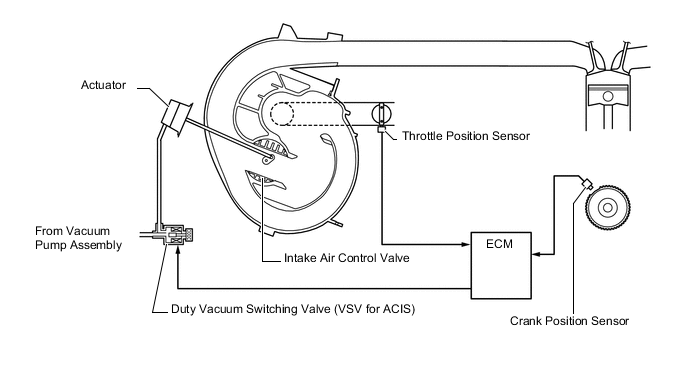
Acoustic Control Induction System (ACIS)
-
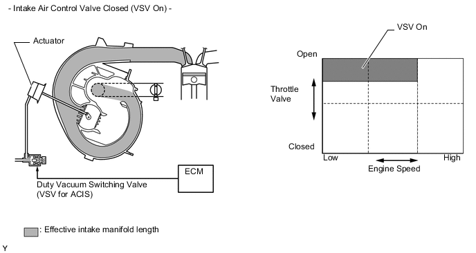
The ACIS uses a bulkhead to divide the intake manifold into 2 stages, with an intake air control valve in the bulkhead being opened and closed to vary the effective length of the intake manifold in accordance with the engine speed and throttle valve opening angle. This increases the power output in all ranges from low to high speed.
-
-
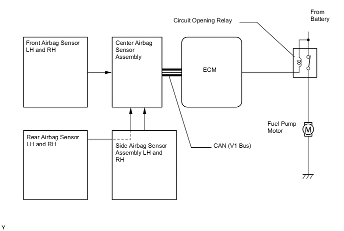
Fuel Pump Control
-
The fuel pump is controlled by the ECM, using the circuit opening relay. The fuel pump control has a fuel cut control. The fuel cut control stops the fuel pump when any of the Supplemental Restraint System (SRS) airbags have deployed.
-
-
Cooling Fan Control
-
The cooling fan control system achieves an optimal fan speed in accordance with the engine coolant temperature, vehicle speed, engine speed, and air conditioning operating conditions*1.
-
-
Starter Control*2
-
On the models with manual transaxle, once the engine switch is pressed, this function operates the starter until the engine starts, provided that the clutch pedal is depressed.
-
On the models with Continuously Variable Transmission (CVT), once the engine switch is pressed, this function operates the starter until the engine starts, provided that the brake pedal is depressed and the shift lever is in P or N.
-
This prevents application of the starter for an inadequate length of time and also prevents the engine from being cranked after it has started.
-
*1: Models with air conditioning
-
*2: Models with entry and start system
-
-
-
-
CONSTRUCTION
-
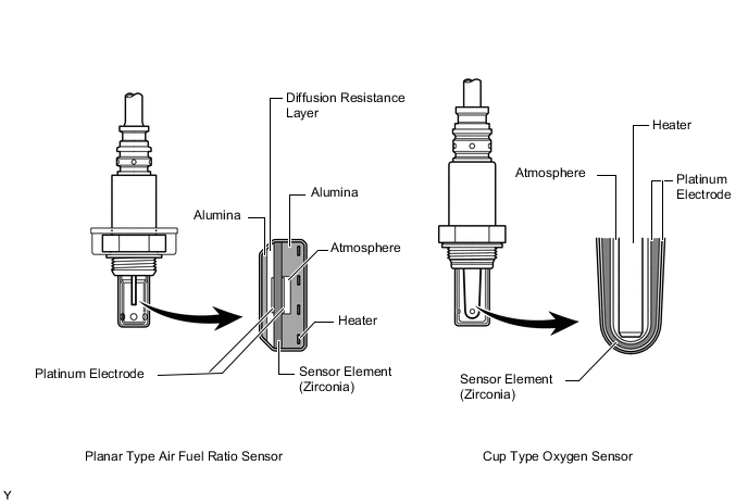
Air Fuel Ratio Sensor and Oxygen Sensor
-
A planar type air fuel ratio sensor and a cup type oxygen sensor are used. The basic construction of the oxygen sensor and the air fuel ratio sensor is the same. However, they are divided into the cup type and the planar type, in accordance with the different types of heater construction used.
-
The planar type air fuel ratio sensor uses alumina, which excels in heat conductivity and electrical insulation, to integrate the sensor element with a heater, thus improving the warm-up performance of the sensor.
-
The cup type oxygen sensor contains a sensor element that surrounds the heater.
-
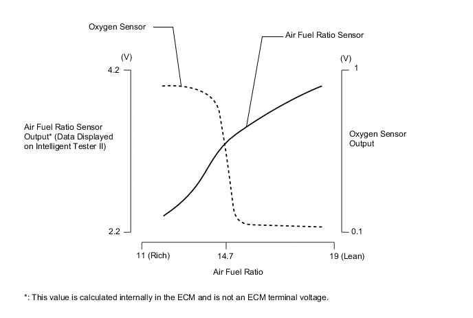
As illustrated below, the conventional oxygen sensor is characterized by a sudden change in its output voltage at the threshold of the stoichiometric air fuel ratio (14.7:1). In contrast, the air fuel ratio sensor data is approximately proportionate to the existing air fuel ratio. The air fuel ratio sensor converts the oxygen density to current and sends it to the ECM. As a result, the detection precision of the air fuel ratio has been improved. The air fuel ratio sensor data can be viewed using an intelligent tester II.
-
-
Intake Mass Air Flow Meter Sub-assembly
-
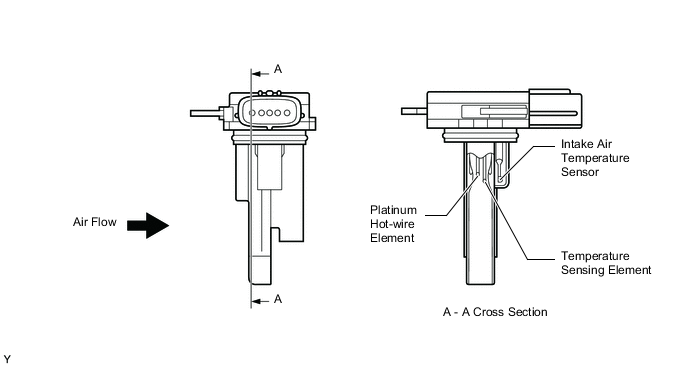
The intake mass air flow meter sub-assembly, which is a slot-in type, allows a portion of the intake air to flow through the detection area. By directly measuring the mass and the flow rate of the intake air, the detection precision has been improved and the intake air resistance has been reduced.
-
This intake mass air flow meter sub-assembly has a built-in intake air temperature sensor.
-
-
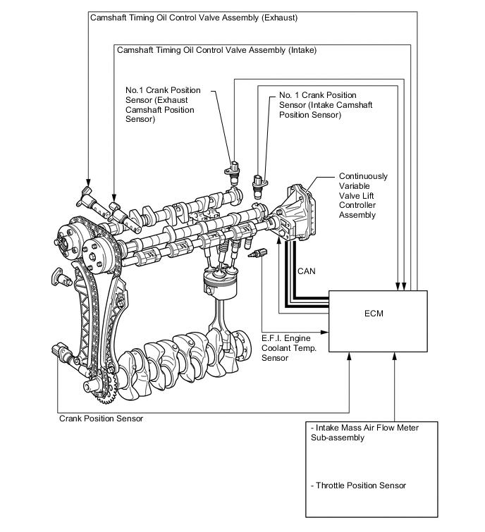
Crank Position Sensor and No. 1 Crank Position Sensor (Camshaft Position Sensor)
-
A pick-up coil type crank position sensor is used. The No. 1 crankshaft position sensor plate of the crankshaft consists of 34 teeth, with 2 teeth missing. The crank position sensor outputs the crankshaft rotation signals every 10°, and the missing teeth are used to determine the top-dead-center.
-
A Magnetic Resistance Element (MRE) type No. 1 crank position sensor (camshaft position sensor) is used. To detect the camshaft position, each timing rotor on the intake and exhaust camshafts is used to generate 3 (3 high output, 3 low output) pulses for every 2 revolutions of the crankshaft.
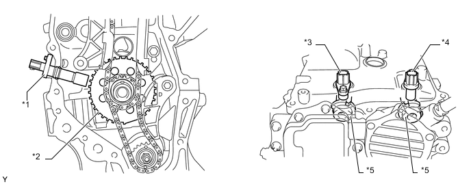
Text in Illustration *1 Crank Position Sensor *2 No. 1 Crankshaft Position Sensor Plate *3 No. 1 Crank Position Sensor (Intake Camshaft Position Sensor) *4 No. 1 Crank Position Sensor (Exhaust Camshaft Position Sensor) *5 Timing Rotor (Camshaft) - - 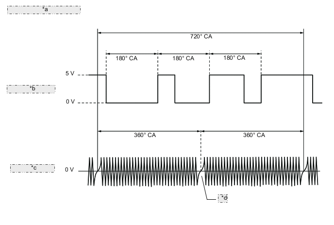
*a - Sensor Output Waveform - *b No. 1 Crank Position Sensor (Intake Camshaft Position Sensor) *c Crank Position Sensor *d 2 Teeth Missing -
The MRE type No. 1 crank position sensor (camshaft position sensor) consists of an MRE, a magnet and a sensor. The direction of the magnetic field changes due to the differing shape (protruded and non-protruded portions) of the timing rotor, which passes by the sensor. As a result, the resistance of the MRE changes, and the output voltage to the ECM changes to high or low. The ECM detects the camshaft position based on this output voltage.
-
The differences between the MRE type No. 1 crank position sensor (camshaft position sensor) and the pick-up coil camshaft position sensor used on the conventional model are as follows:
Item Sensor Type MRE Pick-up Coil Signal Output Constant digital output starts from low engine speeds. Analog output changes with the engine speed. Camshaft Position Detection Detection is made by comparing the NE signals with the high/low output switch timing due to the protruded/non-protruded portions of the timing rotor, or made based on the number of the input NE signals during high/low outputs. Detection is made by comparing the NE signals with the change of waveform that is output when the protruded portion of the timing rotor passes. 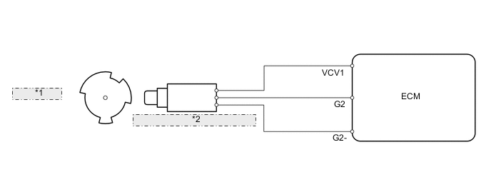
*1 Timing Rotor *2 No. 1 Crank Position Sensor (Camshaft Position Sensor) 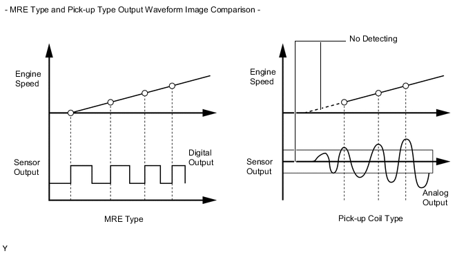
-
-
Throttle Position Sensor
-
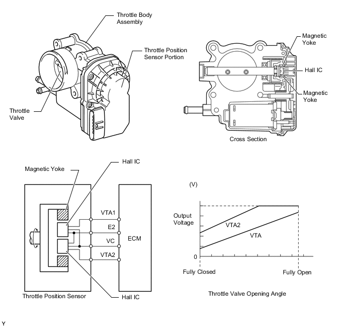
A non-contact type throttle position sensor is used. This sensor uses a Hall IC, which is mounted on the throttle body assembly.
-
The Hall IC is surrounded by a magnetic yoke. The Hall IC converts the changes that occur in the magnetic flux into electrical signals and outputs them as throttle valve effort to the ECM.
-
The Hall IC contains circuits for the main and sub signals. It converts the throttle valve opening angles into electric signals with two differing characteristics and outputs them to the ECM.
-
-
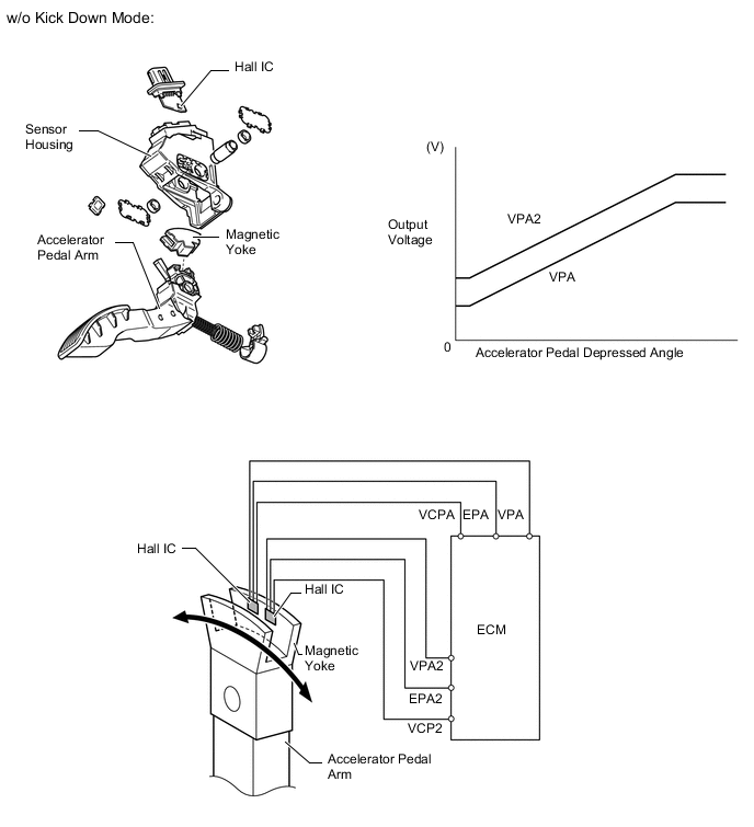
Accelerator Pedal Position Sensor
-
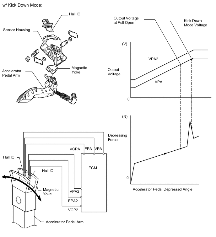
The non-contact type accelerator pedal position sensor uses a Hall IC.
-
The magnetic yoke mounted at the base of the accelerator pedal arm moves around the Hall IC in accordance with the amount of effort applied to the accelerator pedal. The Hall IC converts the changes in the magnetic flux that occur into electrical signals, and outputs them in the form of accelerator pedal effort to the ECM.
-
This accelerator pedal position sensor includes 2 Hall ICs and circuits for the main and sub signals. It converts the accelerator pedal depressed angles into electric signals with two differing characteristics and outputs them to the ECM.
-
On the models with Continuously Variable Transmission (CVT) or cruise control system, when the depressing force applied to the accelerator pedal is greater than a predetermined amount, the ECM detects a "kick down mode" from the VPA signal provided by the accelerator pedal position sensor.
-
-
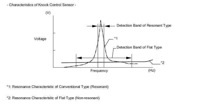
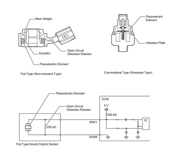
Knock Control Sensor (Flat Type)
-
In a conventional knock control sensor (resonant type), a vibration plate is built into the sensor. This plate has the same resonance point as the knocking* frequency of the engine block. This sensor can only detect vibration in this frequency band.
-
*: The term "Knock" or "Knocking" is used in this case to describe either preignition or detonation of the air fuel mixture in the combustion chamber. This preignition or detonation refers to the air fuel mixture being ignited earlier than is advantageous. This use of "Knock" or "Knocking" is not primarily used to refer to a loud mechanical noise that may be produced by an engine.
-
-
A flat type knock control sensor (non-resonant type) has the ability to detect vibration in a wider frequency band (from approximately 6 kHz to 15 kHz). It has the following features:
-
The engine knocking frequency will vary slightly depending on the engine speed. The flat type knock control sensor can detect vibration even when the engine knocking frequency changes. Due to the use of the flat type knock control sensor, the vibration detection ability has been increased compared to a conventional type knock control sensor, and more precise ignition timing control is possible.
-
A flat type knock control sensor is installed to an engine by placing it over the stud bolt installed on the cylinder block sub-assembly. For this reason, a hole for the stud bolt exists in the center of the sensor.
-
In the sensor, a steel weight is located in the upper portion. An insulator is located between the weight and the piezoelectric element.
-
An open/short circuit detection resistor is integrated in the sensor. When the ignition switch is ON, the open/short circuit detection resistor in the knock control sensor and the resistor in the ECM keep the voltage at terminal KNK1 constant. An Integrated Circuit (IC) in the ECM constantly monitors the voltage of terminal KNK1. If the open/short circuit occurs between the knock control sensor and the ECM, the voltage of terminal KNK1 will change and the ECM will detect the open/short circuit and store a Diagnostic Trouble Code (DTC).
-
Vibrations caused by knocking are transmitted to the steel weight. The inertia of this weight applies pressure to the piezoelectric element. This action generates electromotive force.
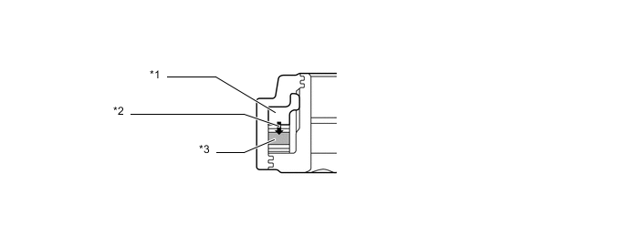
*1 Steel Weight *2 Inertia *3 Piezoelectric Element -
This sensor is mounted in the specific directions and angles illustrated. To prevent water accumulation in the connector, make sure to install the flat type knock control sensor in the position shown in the following illustration:
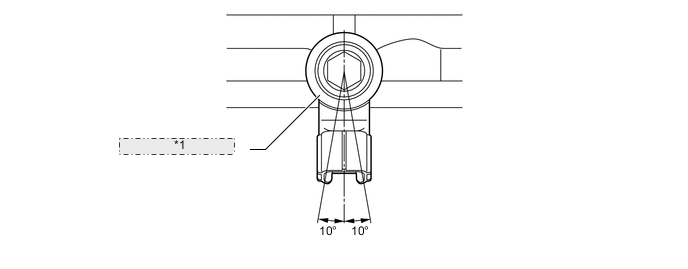
*1 Knock Control Sensor
-
-
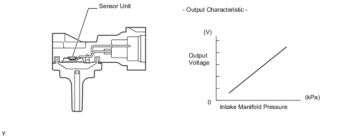
E.F.I. Vacuum Sensor Assembly
-
The E.F.I. vacuum sensor assembly consists of a semiconductor which utilizes the characteristics of a silicon chip that changes its electrical resistance when pressure is applied to it. The sensor converts the intake manifold pressure into an electrical signal, and sends it to the ECM in an amplified form.
-
-
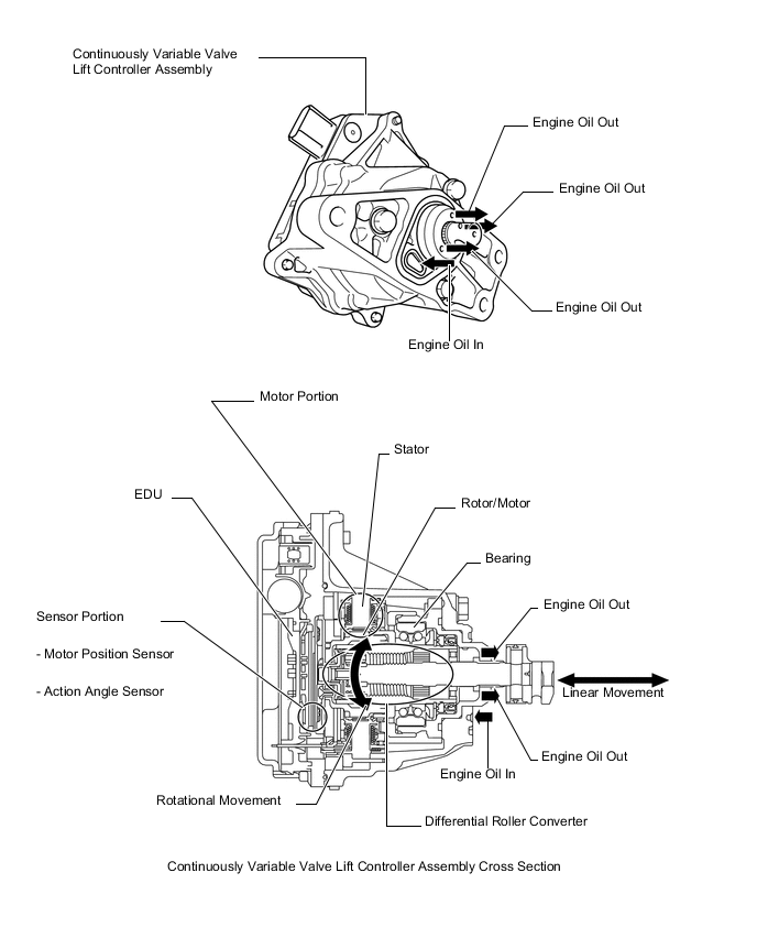
Continuously Variable Valve Lift Controller Assembly
-
The basic components of the continuously variable valve lift controller assembly are an EDU, a brushless motor, and a differential roller converter.
-
The internal gears of the continuously variable valve lift controller assembly are lubricated by engine oil.
-
A neodymium magnet is used in a flat, brushless motor to achieve a compact size. The flat, brushless motor is a DC motor from which the brushes and the commutator have been eliminated. A multipolar magnetized magnet acts as a rotor, which switches the polarity of the voltage applied to the surrounding stator actuation coil in sync with the rotation of the rotor. The resulting alternating field and the rotor magnet magnaflux cause attraction and repulsion to generate torque.
Tech Tips
A neodymium magnet is a type of rare earth magnet composed primarily of neodymium, iron, and boron. It has a high magnaflux density to provide an extremely strong magnetism.
-
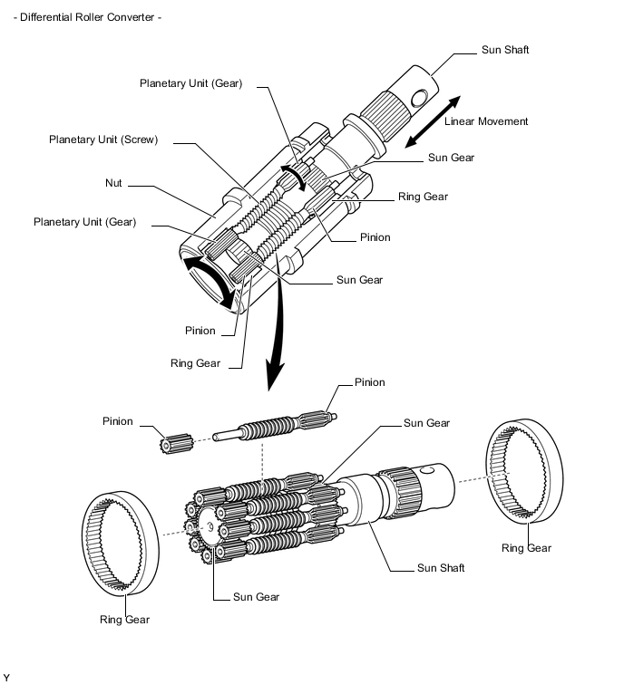
The EDU operates the motor in accordance with signals from the ECM. The differential roller converter converts the rotational movement of the motor into a linear movement. This linear movement operates the VALVEMATIC mechanism.
-
The motor rotates the nut on the differential roller converter. The movement of the nut travels to the planetary unit (gear) and the planetary unit (screw) and causes the sun shaft to move linearly.
-
-
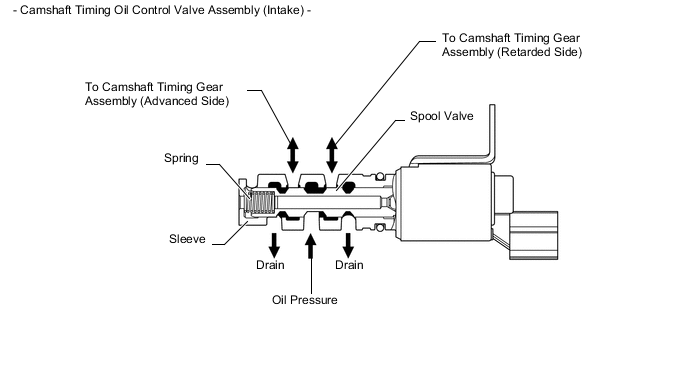
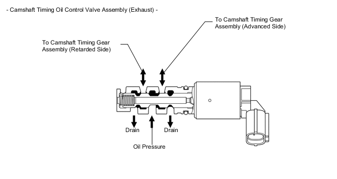
Camshaft Timing Oil Control Valve Assembly
-
This camshaft timing oil control valve assembly controls the spool valve using duty cycle control from the ECM. This allows hydraulic pressure to be applied to the VVT-i controller advanced or retarded side. When the engine is stopped, the camshaft timing oil control valve assembly is in the most retarded position.
-
-
Throttle Control Motor
-
A DC motor with excellent response and minimal power consumption is used for the throttle control motor. The ECM performs the duty cycle control of the direction and the amperage of the current that flows to the throttle control motor in order to regulate the opening of the throttle valve.
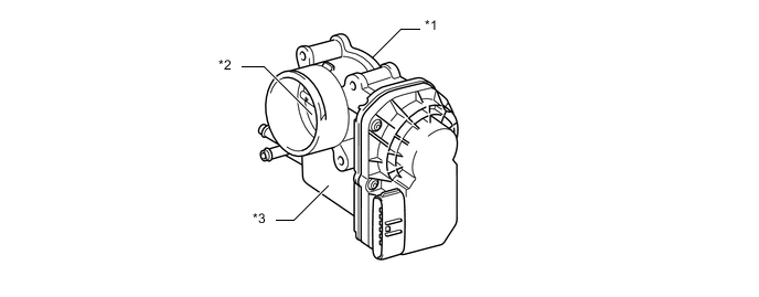
Text in Illustration *1 Throttle Body Assembly *2 Throttle Valve *3 Throttle Control Motor - -
-
-
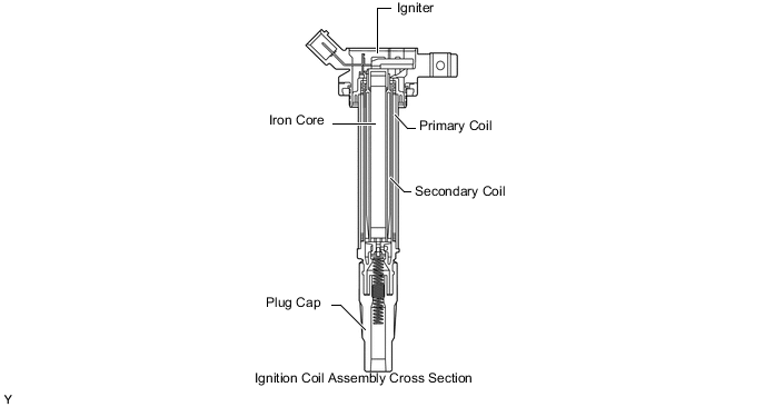
Ignition Coil Assembly
-
The Direct Ignition System (DIS) provides 4 ignition coil assemblies, one for each cylinder. The spark plug caps, which provide contact to spark plugs, are integrated with the ignition coil assembly. Also, an igniter is enclosed to simplify the system.
-
-
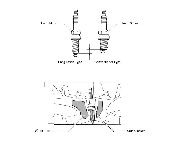
Spark Plug
-
Long-reach, thin-electrode type iridium-tipped spark plugs are used. This type of spark plug allows the area of the cylinder head sub-assembly to receive the spark plugs to be made thick. Thus, the water jacket can be extended near the combustion chamber, which contributes to cooling performance.
-
Iridium-tipped spark plugs improve ignition performance while maintaining the same durability as the platinum-tipped spark plugs.
Tech Tips
Be sure to use a spark plug wrench of the proper size because the size of the spark plugs is different from conventional spark plugs.
-
-
-
OPERATION
-
ETCS-i
-
The ECM drives the throttle control motor by determining the target throttle valve opening in accordance with the respective operating condition.
-
The ECM controls the throttle to an optimal throttle valve opening that is appropriate for the driving conditions such as amount of the accelerator pedal effort and the engine speed in order to achieve excellent throttle control and comfort in all operating ranges.
-
The ECM controls the throttle valve in order to constantly maintain an ideal idle speed.
-
As part of the TRC system, the throttle valve is closed by a request signal from the skid control ECU if an excessive amount of slippage is created at a driving wheel, thus facilitating the vehicle in ensuring stability and driving force.
-
In order to bring the effectiveness of the VSC system control into full play, the throttle valve opening angle is controlled by effecting a coordination control with the skid control ECU.
-
On the models with cruise control system, an ECM with an integrated cruise control ECU directly actuates the throttle valve for operation of the cruise control.
-
The ECM controls the throttle valve in accordance with the operating condition of the VALVEMATIC.
-
-
VALVEMATIC
-
The continuously variable valve lift controller assembly operates the VALVEMATIC mechanism in accordance with signals from the ECM in order to control the amount of intake valve lift and intake valve action angle.
-
The VALVEMATIC effects coordinate control with the Dual VVT-i and ETCS-i.
-
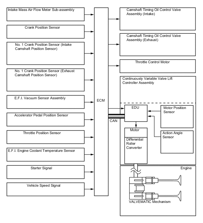
On the basic control, the ECM determines the target intake air volume in accordance with the accelerator pedal depressed angle, engine speed, and various sensor signals. The EDU, which is integrated in the continuously variable valve lift controller assembly, determines the target amount of lift and action angle of the intake valve in accordance with signals from the ECM.
-
To optimize the valve opening and closing timing, the VALVEMATIC effects coordinate control with the Dual VVT-i. Thus, it controls the amount of valve lift and action angle in accordance with the driving conditions. Because the VALVEMATIC features timing advance characteristics in which the amount of valve lift and action angle vary, it effects the proper control to attain the intended amount of valve lift. This VVT-i has timing advance characteristics that differ from the conventional Dual VVT-i control.
-
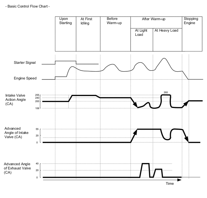
The following table shows the coordinate control of the VALVEMATIC with ETCS-i during basic control:
Control Operation Starting Control VALVEMATIC controls the intake valve action angle, and ETCS-i operates the throttle valve to control the intake air volume. First Idle Control Before Warm-up Control After Warm-up Control
-
VALVEMATIC controls the amount of intake valve lift and intake valve timing, ETCS-i opens the throttle valve wider than the normal opening, and reduces the intake manifold negative pressure in order to minimize pumping loss.
-
During idling, when the intake air volume is small, the ETCS-i controls the intake air volume as in the past.
Engine Stop Control -
-
-
Dual Variable Valve Timing-intelligent (Dual VVT-i) System
-
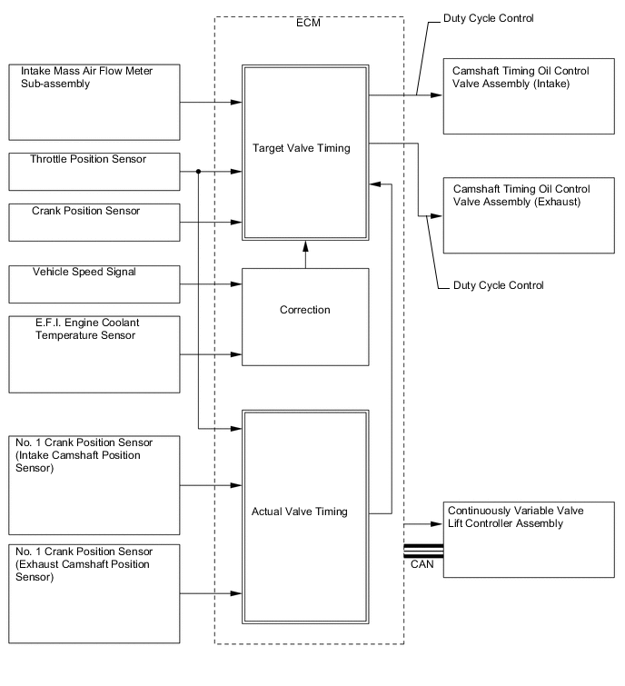
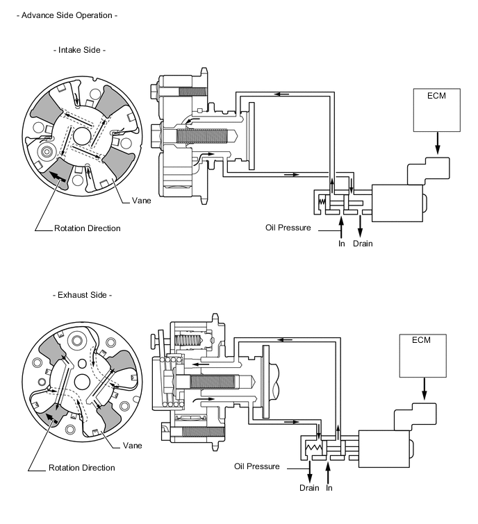
Using the engine speed, intake air mass, throttle position and engine coolant temperature, the ECM can calculate the optimal valve timing for each driving condition and can control the camshaft timing oil control valve assembly. In addition, the ECM uses signals from the crank position sensor and No. 1 crank position sensor (camshaft position sensor) to detect the actual valve timing, thus providing feedback control to achieve the target valve timing.
-
When the camshaft timing oil control valve assembly is positioned as illustrated below by the advance signals from the ECM, the resultant oil pressure is applied to the timing advance side vane chamber to rotate the camshaft in the timing advance direction:
-
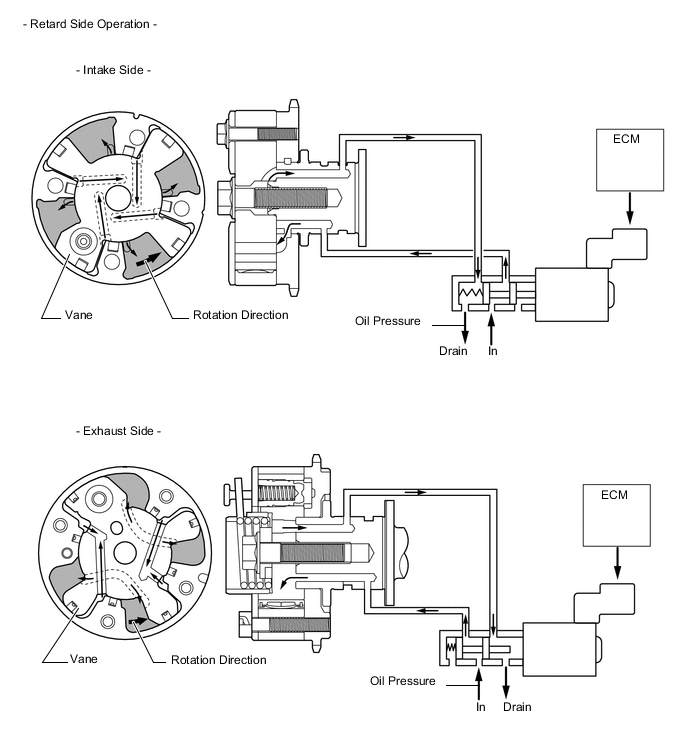
When the camshaft timing oil control valve assembly is positioned as illustrated below by the retard signals from the ECM, the resultant oil pressure is applied to the timing retard side vane chamber to rotate the camshaft in the timing retard direction:
-
After reaching the target timing, the valve timing is held by keeping the camshaft timing oil control valve assembly in the neutral position unless the traveling state changes. This adjusts the valve timing at the desired target position and prevents the engine oil from running out when it is unnecessary.
-
-
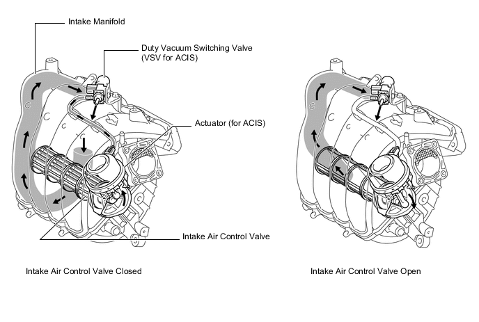
Acoustic Control Induction System (ACIS)
-
The ECM activates the duty vacuum switching valve (VSV for ACIS) to match the longer pulsation cycle so that the negative pressure acts on the diaphragm chamber of the actuator. This closes the intake air control valve. As a result, the effective length of the intake manifold is increased and the intake efficiency in the low-to-medium speed range is improved due to the dynamic effect of the intake air, thereby increasing the power output.
-
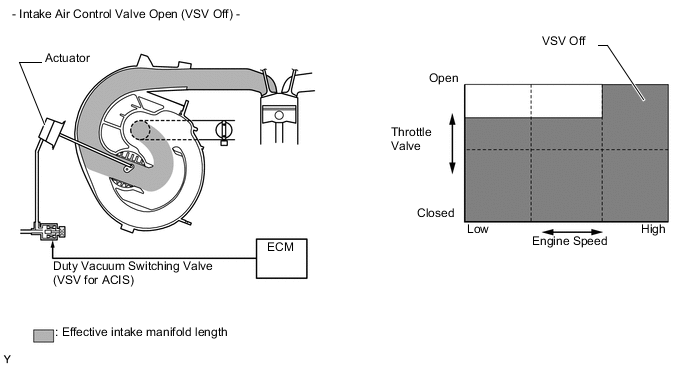
The ECM deactivates the duty vacuum switching valve (VSV for ACIS) to match the shorter pulsation cycle so that atmospheric air is led into the diaphragm chamber of the actuator and opens the intake air control valve. When the intake air control valve is open, the effective length of the intake air chamber is shortened and peak intake efficiency is shifted to the low-to-high engine speed range, thus providing greater output at low-to-high engine speeds.
-
-
Fuel Pump Control
-
When the ECM detects the Supplemental Restraint System (SRS) airbag deployment signal from the center airbag sensor assembly, the ECM will turn the circuit opening relay off. After the fuel cut control has been activated, turning the ignition switch (engine switch*) from off to ON cancels the fuel cut control, and the engine can be restarted.
-
*: Models with entry and start system
-
-
-
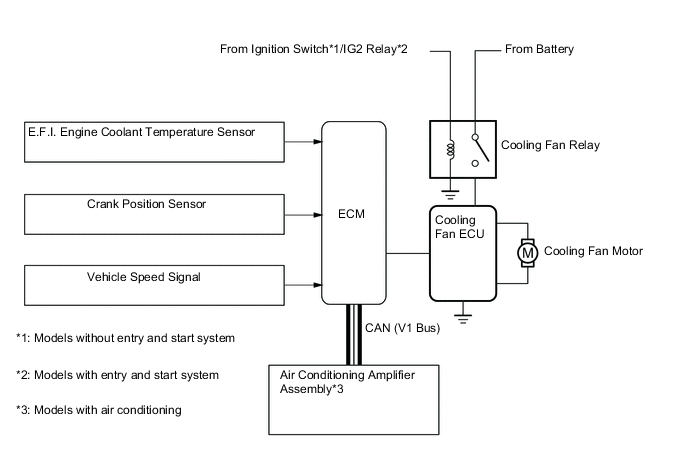
Cooling Fan Control
-
The ECM calculates the cooling fan speed in accordance with the engine coolant temperature, vehicle speed, engine speed, and air conditioning operating conditions, and sends the signals to the cooling fan ECU. Upon receiving the signals from the ECM, the cooling fan ECU actuates the cooling fan motor.
-
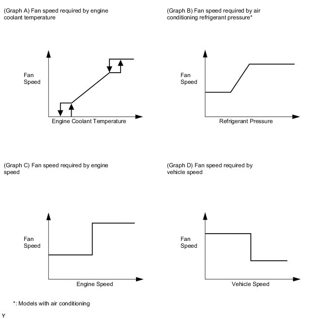
As illustrated below, the ECM determines the required fan speed by selecting the fastest fan speed from among the following:
-
The fan speed required by the engine coolant temperature (Graph A), the fan speed required by the air conditioning refrigerant pressure (Graph B), the fan speed required by the engine speed (Graph C), and the fan speed required by the vehicle speed (Graph D).
-
-
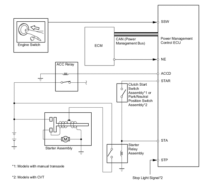
Starter Control (Models with entry and system)
-
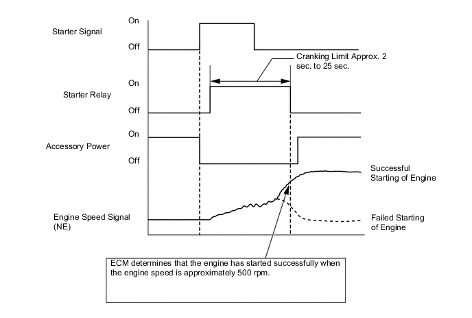
When the driver pushes the engine switch once and the power management control ECU detects a start signal, the power management control ECU will output ACCD and STAR signals and begin cranking. Also, the driver can continue cranking for up to 30 seconds by pushing and holding the engine switch.
-
If the engine speed reaches approximately 500 rpm, the ECM will judge that the engine has started and will send a signal to the power management control ECU using CAN communication. The power management control ECU will then stop the operation of the starter.
-
If CAN communication is cut between the power management control ECU and the ECM, the power management control ECU will receive an engine speed signal (NE) directly from the ECM and will stop the operation of the starter.
-
This system will cut off the power current which activates the accessories while the engine is being cranked. This prevents the intermittent blinking of the accessory lights caused by the voltage instability that occurs during engine cranking.
-
This system has the following protections:
-
The starter will not operate if the engine is operating normally.
-
If the engine switch is pushed and held, cranking will stop once the engine speed reaches a pre-determined level. This prevents the starter from over-revving.
-
If the engine does not start even after approximately 6 seconds of starter operation, the power management control ECU will cancel the starter relay output. Furthermore, if the engine does not start after the engine switch has been pushed and held and cranking has continued for 30 seconds, cranking will be canceled in order to protect the starter.
-
It will not be possible to operate the starter for 2 seconds after engine starting has failed and cranking has been cancelled. This helps to protect the starter.
-
-
-