INTUITIVE PARKING ASSIST SYSTEM DETAILS
-
FUNCTION OF MAIN COMPONENTS
Component Function Clearance Warning ECU Assembly
-
Judges the approximate distance between the vehicle and an obstacle based on signals from the No. 1 ultrasonic sensors. Output signals are sent to the multi-information display.
-
Sounds the No. 1 clearance warning buzzer.
No. 1 Ultrasonic Sensor (6) Detects the distance between the vehicle and an obstacle. No. 1 Clearance Warning Buzzer Sounds to inform the driver according to the distance to the obstacle. Combination Meter Assembly
- Multi-information Display
-
Displays the location of the obstacle and the approximate distance between the vehicle and the obstacle.
-
Displays an indication of malfunction or freezing of a No. 1 ultrasonic sensor to inform the driver.
Back Sonar or Clearance Sonar Switch Assembly Operating this switch allows the operation of intuitive parking assist-sensor system to be enabled or disabled. Air Conditioning Amplifier Assembly Sends outside temperature information to the clearance warning ECU assembly to adjust the distance rate from the No. 1 ultrasonic sensors. Main Body ECU (Multiplex Network Body ECU) Sends model destination information (information to indicate the market the vehicle was built for - such as Canada) to the clearance warning ECU assembly. Power Management Control ECU Transmits the shift position signals to the clearance warning ECU assembly. -
-
OPERATING CONDITION
-
The operating condition of each sensor differs according to its installed position as shown in the table below:
Installation Position Operating Condition Front Corner
-
Power switch is on (IG).
-
System is activated.
-
Shift lever is in a position other than P.
-
Vehicle speed is approximately 10 km/h (6 mph) or less.
Rear Corner
-
Power switch is on (IG).
-
System is activated.
-
Shift lever is in R.
Rear Center
-
Power switch is on (IG).
-
System is activated.
-
Shift lever is in R.
-
-
-
CONSTRUCTION
-
No. 1 Ultrasonic Sensor
-
The No. 1 ultrasonic sensors consist of a microphone and a circuit portion that transmits and receives ultrasonic waves.
-
The circuit portion is filled with urethane to prevent water from entering.
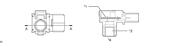
Text in Illustration *1 Circuit Portion *2 Microphone *a A-A Cross Section - -
-
-
-
OPERATION
-
No. 1 Clearance Warning Buzzer
-
Depending on the detection distance and the detection area, the sound pattern of the No. 1 clearance warning buzzer will vary.
Detection Area Detection Distance
(mm (in.))
Buzzer Sound Pattern On
(msec.)
Off
(msec.)
Front Corner Long 500 +/- 50 to 400 +/- 40 (19.7 +/- 2.0 to 15.7 +/- 1.6) 150 +/- 15 150 +/- 15 Middle 400 +/- 40 to 300 +/- 30 (15.7 +/- 1.6 to 11.8 +/- 1.2) 75 +/- 7.5 75 +/- 7.5 Short 300 +/- 30 or less (11.8 +/- 1.2 or less) Continuous Sound 0 Rear Corner Long 600 +/- 60 to 450 +/- 50 (23.6 +/- 2.4 to 17.7 +/- 2.0) 150 +/- 15 150 +/- 15 Middle 450 +/- 50 to 300 +/- 30 (17.7 +/- 2.0 to 11.8 +/- 1.2) 75 +/- 7.5 75 +/- 7.5 Short 300 +/- 30 or less (11.8 +/- 1.2 or less) Continuous Sound 0 Rear Center Longest 1500 +/- 150 to 600 +/- 60 (59.1 +/- 5.9 to 23.6 +/- 2.4) 150 +/- 1.5 650 +/- 65 Long 600 +/- 60 to 450 +/- 50 (23.6 +/- 2.4 to 17.7 +/- 2.0) 150 +/- 1.5 150 +/- 1.5 Middle 450 +/- 50 to 350 +/- 40 (17.7 +/- 2.0 to 13.8 +/- 1.6) 75 +/- 7.5 75 +/- 7.5 Short 350 +/- 40 or less (13.8 +/- 1.6 or less) Continuous Sound 0 -
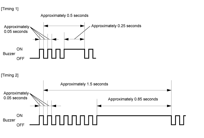
The No. 1 ultrasonic sensors are divided into 2 groups: a front section group (front corners) and a rear section group (rear corners and rear centers). If multiple No. 1 ultrasonic sensors detect obstructions at the same time, the No. 1 clearance warning buzzer sounds as follows, in accordance with the detection distance and detection area of each group:
Buzzer Sound Pattern ON/OFF Time (msec.) Detection Distance Short (*A) Middle (*A) Long (*A) Not detected Short (*B) Timing 1 Timing 2 Timing 2 Continuous Sound/0 Middle (*B) Timing 2 75/75 75/75 75/75 Long (*B) Timing 2 75/75 150/150 150/150 Longest (*B) Timing 2 75/75 150/150 150/650 Not detected Continuous Sound/0 75/75 150/150 None
-
*A: Front section
-
*B: Rear section
-
-
-
Multi-information Display
-
The items displayed by the multi-information display are the location of the obstacle and the approximate distance between the vehicle and the obstacle.
-
The number of lines shown on the display changes based on the actual distance and flashes when the distance is short.
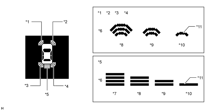
Text in Illustration *1 Front Corner LH *2 Front Corner RH *3 Rear Corner LH *4 Rear Corner RH *5 Rear Center *6 Distance *7 Longest *8 Long *9 Middle *10 Short *11 Flashes - - -
The items displayed by the multi-information display are warning messages relating to No. 1 ultrasonic sensor malfunction, No. 1 ultrasonic sensor freezing, or presence of dirt on the No. 1 ultrasonic sensor.
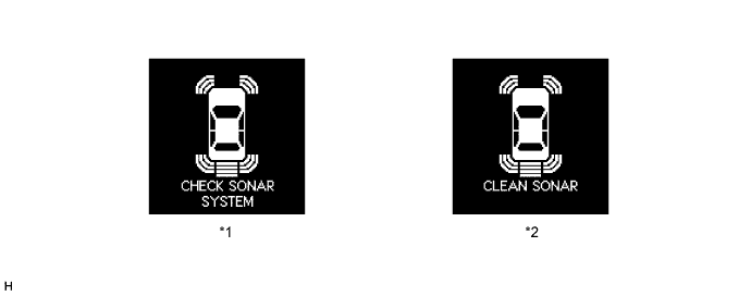
Text in Illustration *1 Malfunctioning *2 Frozen/Dirty
-
-
Detection Area
-
The detection areas of the No. 1 ultrasonic sensor are as shown in the following illustration.
-
These detection areas are applicable when positioning a 60 mm (2.36 in.) diameter pole parallel or perpendicular to the ground. The ranges vary depending on the measuring method and type of obstacle.
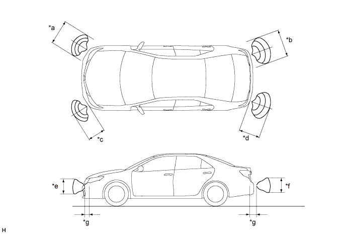
Text in Illustration (Corner Area:) *a Approximately 700 mm (27.6 in.) *b Approximately 750 mm (29.5 in.) *c Approximately 500 mm (19.7 in.) *d Approximately 600 mm (23.6 in.) *e Approximately 400 mm (15.7 in.) *f Approximately 400 mm (15.7 in.) *g Approximately 200 mm (7.9 in.) - - 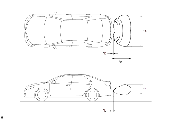
Text in Illustration (Rear Center Area:) *a Approximately 1800 mm (70.9 in.) *b Approximately 200 mm (7.9 in.) *c Approximately 1000 mm (39.4 in.) *d Approximately 500 mm (19.7 in.)
-
-
-
DIAGNOSIS
-
If a system malfunction is detected, the clearance warning ECU assembly stores Diagnostic Trouble Codes (DTCs) in its memory. For details, refer to the Repair Manual.
-