FRONT SUSPENSION SYSTEM DETAILS
-
CONSTRUCTION
-
Front Suspension Support Sub-assembly and Front Coil Spring
-
A split-input type structure has been adopted for the front suspension support sub-assembly to ensure excellent quietness and ride comfort.
-
While driving, the input from the tires is transferred to the body via the front shock absorber assembly, front spring bumper and front coil spring. With a split-input type structure, the input from the front shock absorber assembly is transferred to the body via the rubber portion of the front suspension support sub-assembly. The input from the front coil spring and front spring bumper are transferred to the body via the strut bearing. The input from the front shock absorber assembly, and the input from the front coil spring and front spring bumper are received separately, realizing excellent quietness and ride comfort.
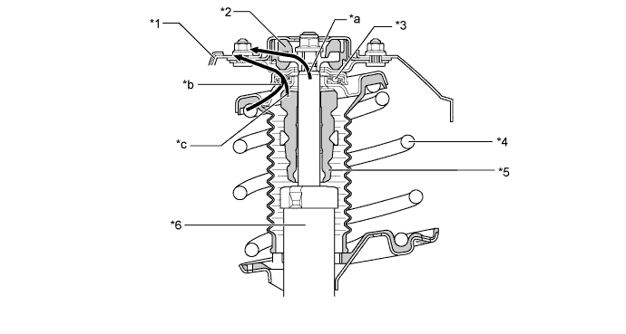
Text in Illustration *1 Body *2 Front Suspension Support Sub-assembly *3 Strut Mounting Bearing *4 Front Coil Spring *5 Front Spring Bumper *6 Front Shock Absorber Assembly *a Front Shock Absorber Assembly Input *b Front Coil Spring Input *c Front Spring Bumper Input - - -
A pigtail type of front coil spring is used where the top and bottom diameters are different, creating a compact and lightweight construction. Lateral force reduction springs are used to control the reaction force line of the front coil spring, and reduce the bending force applied to the front shock absorber assembly. This reduces suspension friction, realizing a very comfortable ride.
-
-
Front Shock Absorber Assembly
-
In the front shock absorber assembly, a low-pressure N2gas sealed type construction is used to suppress cavitations and a multi-leaf type liner control valve is also used to attain the linear damping force characteristics, offering both driving stability and riding comfort.
Note
To prevent hazardous conditions, make sure to empty the gas from the shock absorber before discarding an N2gas sealed shock absorber. For details, refer to the Repair Manual.
-
Since the multi-leaf type linear control valve has a laminate-structure backing valve, it enables the damping force to be generated at lower piston speeds, compared with a structure that generates the damping force with only the base valve when compression force is applied.
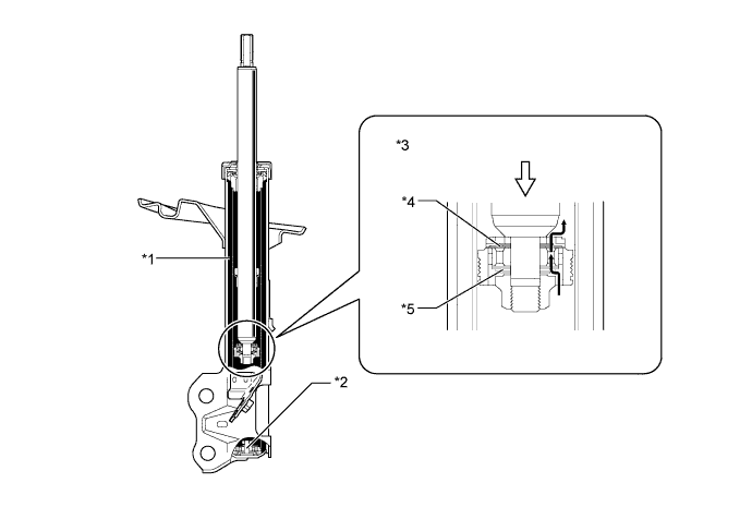
Text in Illustration *1 Low-pressure N2Gas
*2 Base Valve *3 Multi-leaf Type Linear Control Valve *4 Backing Valve *5 Inner Valve - - 
Oil Flow 
Compression Force -
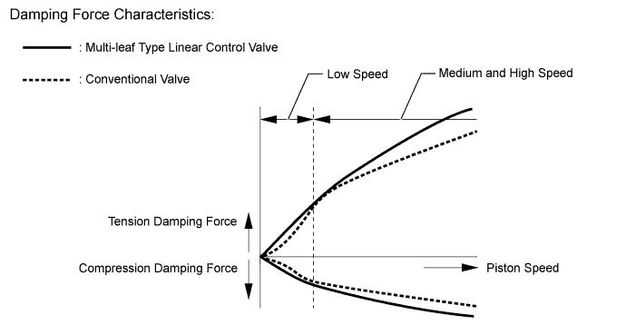
The illustration below shows a comparison of multi-leaf type linear control valve and conventional valve damping force characteristics.
-
-
Front Lower No. 1 Suspension Arm Sub-assembly
-
An L-shaped front lower No. 1 suspension arm sub-assembly, of which the cross section structure is closed, has been provided. As a result, in addition to the material thickness having been made thinner, the cross section and arm shape have been optimized, thus, achieving both a light weight and high rigidity at the same time.
-
The spring rate of the lower No. 1 arm bush have been increased to ensure the proper support rigidity of the front lower No. 1 suspension arm. As a result, excellent steering feel and stability have been achieved.
-
The front lower No. 2 arm bush is a vertical axis type. It is a perpendicular bulge type bushing that gives a soft ride.
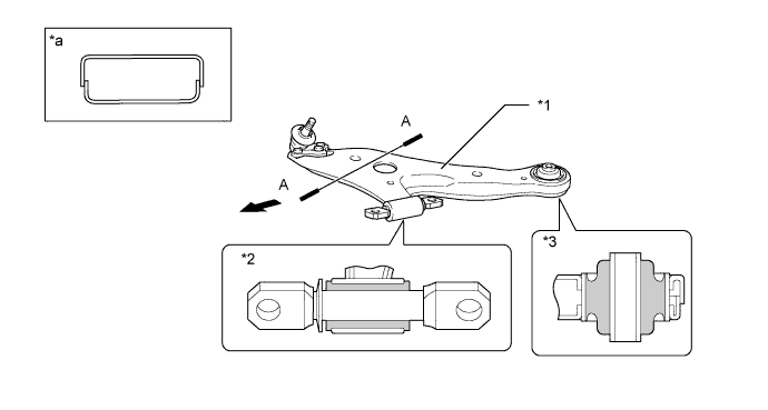
Text in Illustration *1 Front Lower No. 1 Suspension Arm Sub-assembly *2 Front Lower No. 1 Arm Bush (Cross Section) *3 Front Lower No. 2 Arm Bush (Cross Section) - - *a A-A Cross Section - - Front - -
-
-
Front Stabilizer Bar
-
The front stabilizer bar is a solid bar.
-
Ball joint links are used to join the front stabilizer bar to the suspension, which enhances the response during the initial stages of a roll.
-
The front stabilizer link assemblies are mounted to the struts so that the joint between the stabilizer and the suspension can be located further outward of the vehicle. This helps the stabilizer to follow postural changes and thus optimize the roll.
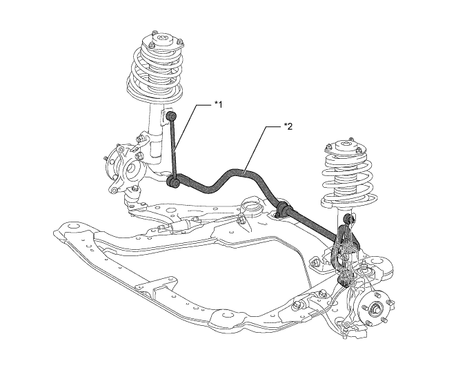
Text in Illustration *1 Front Stabilizer Link Assembly *2 Front Stabilizer Bar
-
-