POWER STEERING SYSTEM DETAILS
-
FUNCTION OF MAIN COMPONENTS
-
The main components of the EPS system are as follows:
Component Function Steering Column Assembly Power Steering ECU Assembly Actuates the power steering motor mounted on the steering column assembly to provide power assist, based on the signals received from various sensors and ECUs. Torque Sensor Detects the amount of twist of the torsion bar. Based on the torque that is applied to the torsion bar, the sensor creates an electrical signal, and outputs this signal to the power steering ECU assembly. Power Steering Motor Generates assist torque in accordance with a signal received from the power steering ECU assembly. Rotation Angle Sensor* Located in the brushless type power steering motor, this sensor detects the rotation angle of the motor and outputs a signal to the power steering ECU assembly. Reduction Mechanism Reduces the speed of the power steering motor through the use of a worm gear and a wheel gear and transmits it to the column shaft. Skid Control ECU
-
Outputs the vehicle speed signal to the power steering ECU assembly.
-
Requests steering torque assist during steering cooperative control.
Air Conditioning Amplifier Assembly Receives a signal from the power steering ECU assembly limit the electrical usages. Combination Meter Assembly EPS Warning Light
-
Illuminates to alert the driver when the power steering ECU assembly detects a malfunction in the EPS system.
-
If the power steering ECU assembly detects voltage drop in a battery, it will illuminate the EPS warning light.
Buzzer Sounds to warn the driver of a malfunction in the system. ECM Outputs the engine speed signal to the power steering ECU assembly.
-
*: Except base models
-
-
-
SYSTEM CONTROL
-
The EPS system has the following controls:
Control Outline Basic Control Calculates the assist current from the steering torque value and the vehicle speed, and actuates the power steering motor. Inertia Compensation Control Ensures the starting movement of the power steering motor when the driver starts to turn the steering wheel. Recovery Control During the short interval between the times the driver fully turns the steering wheel and the wheels try to recover, this control assists the recovery force. Damper Control Regulates the amount of assist when the driver turns the steering wheel while driving at high speeds, thus damping the changes in the yaw rate of the vehicle body. System Overheat Protection Control Estimates the power steering motor temperature based on the amperage and the length of time the amperage has been applied for. If the temperature exceeds the standard, it limits the amperage to prevent the power steering motor from overheating. Electric Load Control Prevents a reduction of assist torque if the battery voltage decreases. Cooperative Control (Brake Control System) The power steering ECU assembly performs cooperative control with the skid control ECU, in order to control the steering assist torque in accordance with information received from the skid control ECU. This facilitates the steering operation of the driver, thus realizing a high level of vehicle stability. For details, Click here.
-
Electric Load Control
-
When the power steering ECU assembly detects the battery voltage decrease, it transmits the electric load control signal to the air conditioning amplifier assembly in order to limit the electrical usage.
-
The air conditioning amplifier assembly limits operation of rear window defogger and mirror heater until the power steering ECU assembly releases the limitation demand.
-
-
-
CONSTRUCTION
-
Steering Column Assembly (Models with 2AR-FE Engine)
-
The steering column assembly includes a torque sensor, power steering motor, power steering ECU assembly and reduction mechanism.
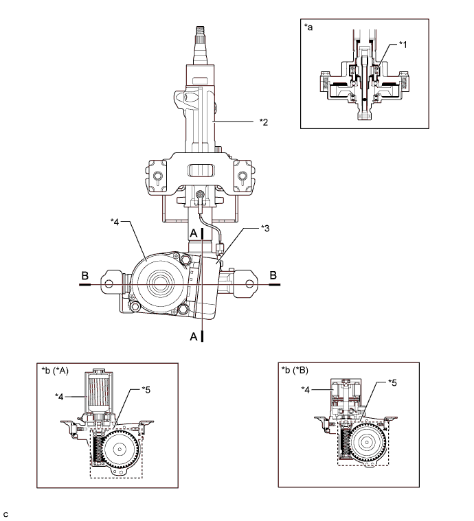
Text in Illustration *A Base Models *B Except Base Models *1 Torque Sensor *2 Steering Column Assembly *3 Power Steering ECU Assembly *4 Power Steering Motor Assembly *5 Reduction Mechanism - - *a A-A Cross Section *b B-B Cross Section -
The power steering torque sensor is built into the steering column assembly. A multipole magnet is mounted to the input shaft, and a yoke is mounted to the output shaft. The input and output shafts are joined by a torsion bar.
-
The power steering torque sensor contains 2 Hall ICs which face opposite to each other. The system detects the steering direction in accordance with the direction of the magnetic flux that passes between the Hall ICs. Furthermore, the system detects steering torque in accordance with the amount of change in the magnetic flux density based on the relative displacement of the multipole magnet and the yoke. The power steering ECU assembly monitors the torque sensor signals output by the 2 Hall ICs to detect malfunctions.
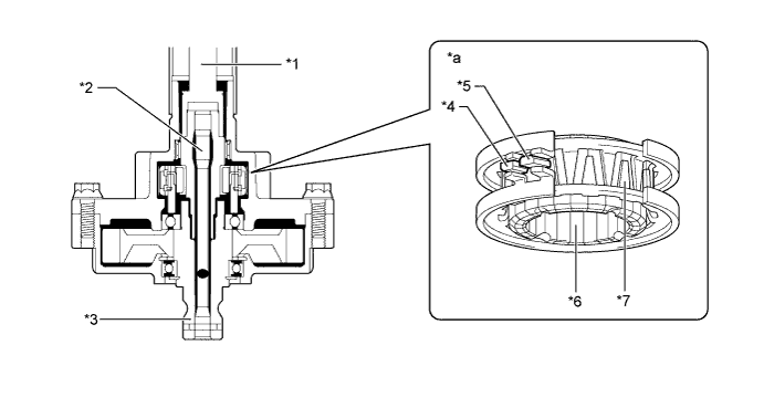
Text in Illustration *1 Input Shaft *2 Torsion Bar *3 Output Shaft *4 Hall IC 2 *5 Hall IC 1 *6 Multipole Magnet *7 Yoke - - *a Power Steering Torque Sensor - -
-
-
Steering Column Assembly (Models with 2GR-FE Engine)
-
The steering column assembly consists of an electric power steering column sub-assembly, power steering motor assembly and power steering ECU assembly.
-
The electrical power steering column sub-assembly includes a torque sensor and reduction mechanism.
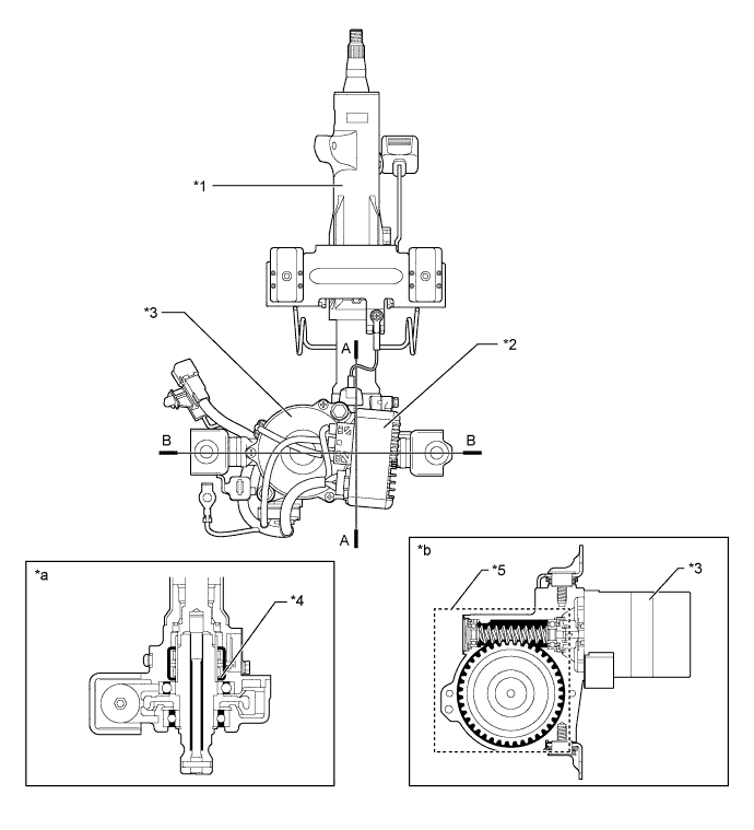
Text in Illustration *1 Electrical Power Steering Column Sub-assembly *2 Power Steering ECU Assembly *3 Power Steering Motor Assembly *4 Torque Sensor *5 Reduction Mechanism - - *a A-A Cross Section *b B-B Cross Section -
The torque sensor consists of a sleeve, stub shaft and 2 detection coils.
-
The sleeve is mounted on the input shaft, and the stub shaft is mounted on the output shaft. The input shaft and the output shaft are joined by the torsion bar. The detection coils are placed on the outside of the sleeve to complete an excitation circuit without making contact.
-
When the steering wheel is turned, the twist that is created in the torsion bar creates a relative displacement between the sleeve and the stub shaft. The torque sensor outputs this change as an electrical signal to the power steering ECU assembly.
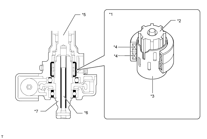
Text in Illustration *1 Torque Sensor *2 Stub Shaft *3 Sleeve *4 Detection Coil *5 Input Shaft *6 Torsion Bar *7 Output Shaft - -
-
-
Power Steering Motor
-
A brush type power steering motor assembly is used on base models.
-
A brushless type power steering motor assembly is used on models other than base models.
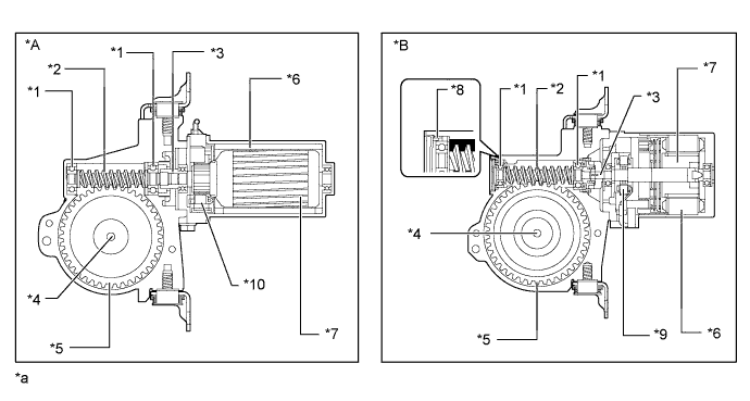
Text in Illustration *A Base Models (Brush Type Power Steering Motor) *B Except Base Models (Brushless Type Power Steering Motor) *1 Ball Bearing *2 Worm Gear *3 Motor Shaft *4 Column Shaft *5 Wheel Gear *6 Stator *7 Rotor *8 Leaf Spring *9 Rotation Angle Sensor *10 Brush *a This illustration is an example only. - - -
The construction of the power steering motor assembly is as follows:
Motor Type Construction Brush Type Power Steering Motor Assembly and Brushless Type Power Steering Motor Assembly
-
The torque that is generated by the power steering motor is transmitted via the joint to the reduction mechanism.
-
The reduction mechanism reduces the speed of the power steering motor via the worm gear and the wheel gear, and transmits it to the column shaft.
-
The wheel gear is made of a high strength, low friction, and low wear plastic material, to realize low noise and a lightweight construction.
-
The worm gear is supported by the ball bearings in order to reduce noise and frictions.
Brush Type Power Steering Motor Assembly The power steering motor assembly consists of a rotor, stator and motor shaft. Brushless Type Power Steering Motor Assembly
-
The power steering motor assembly consists of a rotor, stator, motor shaft and rotation angle sensor.
-
The rotation angle sensor consists of a highly reliable and durable resolver sensor.
-
A leaf spring in worm gear is provided to ensure optimal gear engagement at all times.
-
-
-
-
OPERATION
-
Power Steering Torque Sensor (Models with 2AR-FE Engine)
-
When the steering wheel is not turned:
-
If the vehicle is driven straight and the driver does not turn the steering wheel, the yoke is centered between the N and S poles of the multipole magnet. Thus, no magnetic flux passes between the Hall ICs. In this case, the Hall ICs output a specified voltage to the power steering ECU assembly, to indicate that no turning torque is being applied to the steering wheel. Therefore, current is not applied to the motor.
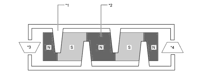
Text in Illustration *1 Yoke Tab *2 Multipole Magnet *3 Hall IC 2 *4 Hall IC 1
-
-
When the steering wheel is turned right or left:
-
When the driver turns the steering wheel to the right or left, the twist created in the torsion bar creates a relative displacement between the multipole magnet and yoke.
-
At this time, the magnetic flux from the N to S poles of the multipole magnet passes between the Hall ICs. The system detects the direction the steering wheel is being turned in accordance with the direction of the magnetic flux that passes between the Hall ICs. Hall IC1 and Hall IC2 are installed facing opposite to each other. As a result, the output characteristics of the 2 Hall ICs are constantly opposite each other. The system monitors the different outputs of these Hall ICs in order to detect malfunctions.
-
The magnetic flux density becomes higher as the Hall ICs get closer to the center of each respective pole. Each Hall IC converts these magnetic flux fluctuations into voltage fluctuations in order to transmit the rotational torque of the steering wheel to the power steering ECU assembly.
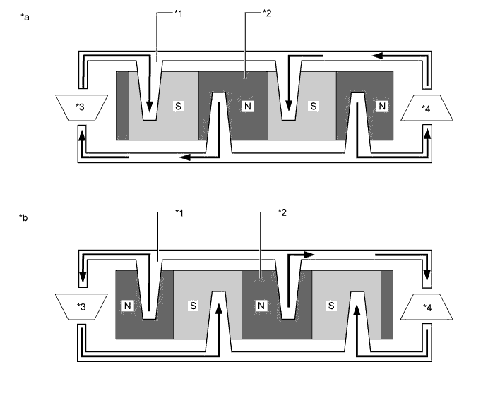
Text in Illustration *1 Yoke Tab *2 Multipole Magnet *3 Hall IC 2 *4 Hall IC 1 *a When the steering wheel is turned right *b When the steering wheel is turned left 
Direction of the Magnetic Flux - -
-
-
-
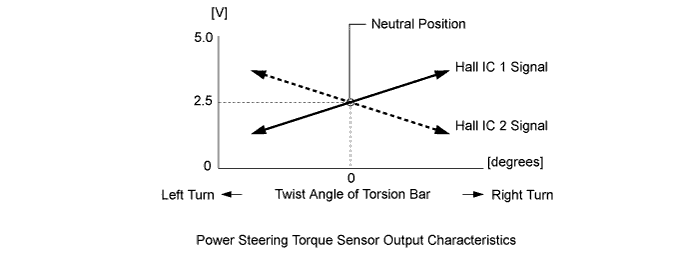
Power Steering Torque Sensor Output Characteristics (Models with 2AR-FE Engine)
-
When the driver does not turn the steering wheel, the power steering torque sensor outputs a specified voltage (2.5 V) to the power steering ECU assembly. As long as the specified voltage is output, the power steering ECU assembly determines that no turning torque is being applied to the steering wheel.
-
When the driver turns the steering wheel to the right or left, the voltage output from the power steering torque sensor to the power steering ECU assembly changes. Based on the changes, the power steering ECU assembly determines the steering torque and steering direction input by the driver.
-
-
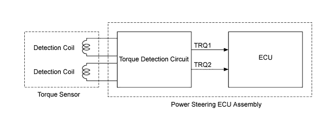
Power Steering Torque and Steering Direction Detection (Models with 2GR-FE Engine)
-
The torque detection circuit built in the power steering ECU assembly calculates the torque sensor 1 output (TRQ1) and the torque sensor 2 output (TRQ2) in accordance with the signals from the 2 detection coils of the torque sensor.
-
The power steering ECU assembly detects the steering torque and the steering direction according to TRQ1 and TRQ2.
-
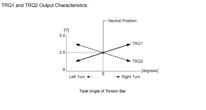
When the driver does not turn the steering wheel, TRQ1 and TRQ2 output a specified voltage (approximately 2.5 V). As long as the specified voltage is output, the power steering ECU determines that steering torque is not being generated.
-
When the driver turns the steering wheel to the right or left, TRQ1 and TRQ2 changes as shown in the graph below. Based on the changes, the power steering ECU assembly determines the steering torque and steering direction input by the driver.
-
-
-
FAIL-SAFE
-
If the power steering ECU assembly detects a malfunction in the EPS system, the power steering ECU assembly illuminates the EPS warning light and sounds the buzzer to inform the driver.
-
If a system malfunction occurs, the power steering ECU assembly changes control mode to fail-safe mode. For details, refer to the Repair Manual.
-
-
DIAGNOSIS
-
The power steering ECU assembly will also store Diagnostic Trouble Codes (DTCs). The DTC can be accessed through the use of the Techstream. For details, refer to the Repair Manual.
-