BRAKE CONTROL SYSTEM DETAILS
-
FUNCTION OF MAIN COMPONENTS
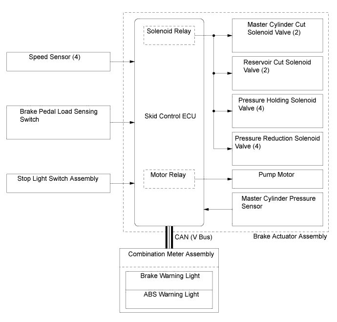
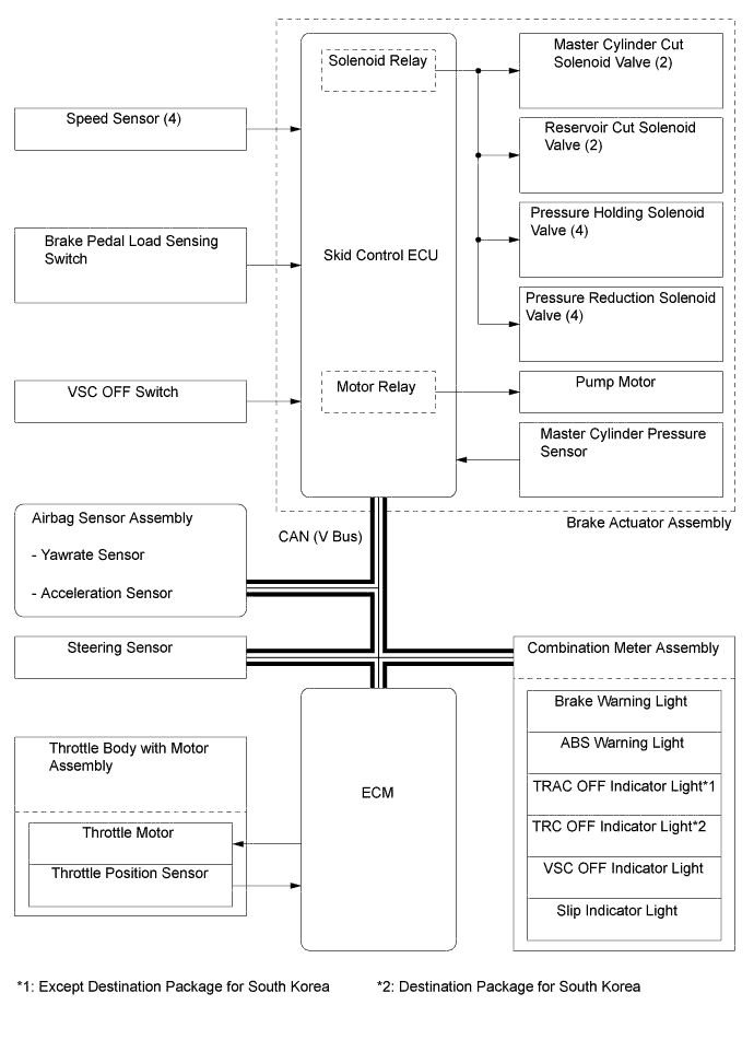
Component Function Brake Actuator Assembly Skid Control ECU Judges the vehicle driving condition based on the signals from each sensor and switch, and sends the brake control signals to the brake actuator. Solenoid Relay (Built into Skid Control ECU) Supplies power to the solenoid valves. Motor Relay (Built into Skid Control ECU) Supplies power to the pump motor. Solenoid Valves
-
The hydraulic circuit has 2 master cylinder cut solenoid valves, 2 reservoir cut solenoid valves, 4 pressure holding solenoid valves and 4 pressure reduction solenoid valves.
-
Change the fluid path based on the signals from the skid control ECU during the operation of the brake control system functions, in order to control the fluid pressure applied to the wheel cylinders.
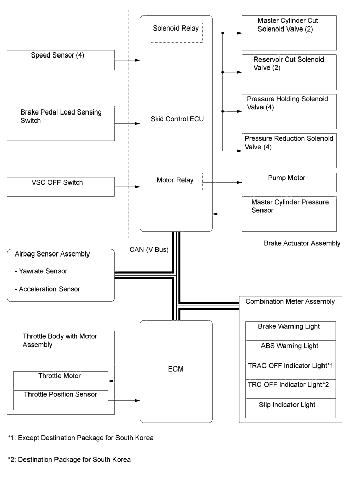
Pump Motor Drives the pumps inside the brake actuator. Master Cylinder Pressure Sensor Detects the master cylinder pressure. Speed Sensors Detect the wheel speed of each of the 4 wheels. Airbag Sensor Assembly
-
The airbag sensor assembly incorporates the acceleration sensor and yawrate sensor.
-
The yawrate sensor detects the vehicle's yaw rate.
-
The acceleration sensor detects the vehicle's longitudinal and lateral acceleration.
-
The airbag sensor assembly sends the detection signals from the yawrate sensor and acceleration sensor to the skid control ECU via the CAN communication.
Steering Sensor Detects the steering direction and angle of the steering wheel. Stop Light Switch Assembly Detects the brake pedal depressing signal. Parking Brake Switch Assembly Detects the parking brake pedal status. VSC OFF Switch Enables the driver to select "Normal mode", " TR(A)C OFF mode", or "VSC OFF mode". Main Body ECU (Multiplex Network Body ECU) Sends the parking brake switch signal to the skid control ECU. ECM
-
Sends the throttle position signal, accelerator pedal position signal, engine speed signal etc., to the skid control ECU.
-
Based on the signals from the skid control ECU, controls the engine output.
Combination Meter Assembly Brake Warning Light
-
Illuminates to alert the driver when the skid control ECU detects a malfunction in the EBD or brake system.
-
Illuminates to alert the driver when the brake fluid level is low.
-
Illuminates to inform the driver when the parking brake is engaged.
ABS Warning Light Illuminates to alert the driver when the skid control ECU detects a malfunction in the ABS. TR(A)C OFF Indicator Light Illuminates to inform the driver when TR(A)C OFF mode is selected. VSC OFF Indicator Light Illuminates to inform the driver when VSC OFF mode is selected. Slip Indicator Light
-
Blinks to inform the driver when the TR(A)C or VSC is performing control.
-
Illuminates to alert the driver when the skid control ECU detects a malfunction in the TR(A)C and/or VSC.
Master Warning Light* Illuminates to alert the driver when a message is being displayed on the multi-information display. Multi-information Display* Shows a warning message to alert the driver, such as when the vehicle is being driven with the parking brake still engaged. Buzzer Sounds to alert the driver when the vehicle is being driven with the parking brake still engaged.
-
*: Destination package for South Korea
-
-
SYSTEM CONTROL
-
Table of System Control
-
The brake control system has the following system/functions:
Control Outline Anti-lock Brake System (ABS) Helps prevent the wheels from locking when the brakes are applied firmly or when braking on a slippery surface. Electronic Brake Force Distribution (EBD) Utilizes ABS, realizing proper brake force distribution between the front and rear wheels in accordance with the driving conditions. In addition, during braking while cornering, it also controls the brake forces of the right and left wheels, helping maintain vehicle behavior. Brake Assist The primary purpose of Brake Assist is to provide supplementary brake force to assist a driver who cannot generate a large brake force during emergency braking, thus helping ensure the vehicle's braking performance. Traction Control (TR(A)C) Helps restrain the slippage of the drive wheels if the driver depresses the accelerator pedal excessively when starting off or accelerating on a slippery surface. Vehicle Stability Control (VSC) Helps restrain sideways slippage of the vehicle during a strong understeer tendency or strong oversteer tendency while cornering.
-
-
Anti-lock Brake System (ABS)
-
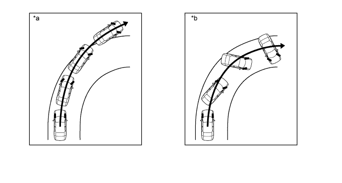
The ABS helps prevent the wheels from locking during sudden braking or braking on a slippery surface. This helps provide the appropriate braking force for the road surface conditions, thus ensuring vehicle stability and excellent braking performance.
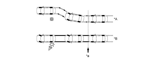
Text in Illustration *A With ABS *B Without ABS *a Brake Operation - -
-
-
Electronic Brake Force Distribution (EBD)
-
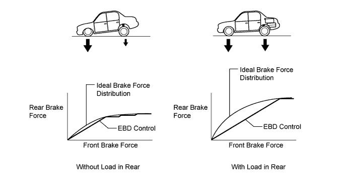
This function controls the brake force that acts on the rear wheels in accordance with the changes in the vehicle conditions such as load factors or deceleration, in order to ensure excellent braking performance.
-
During braking while cornering, this function controls the brake force that acts on the left and right wheels in accordance with the vehicle conditions at that time. This ensures vehicle stability and excellent braking performance.

Text in Illustration 
Brake Force 
Control Moment
-
-
Brake Assist
-
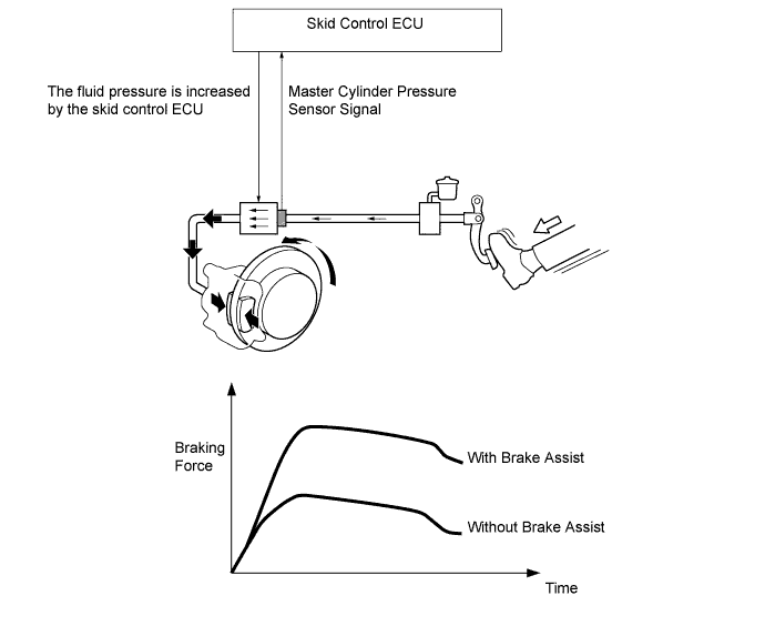
With brake assist, based on the signals from the master cylinder pressure sensor, the skid control ECU calculates the speed with which and the amount the brake pedal is applied to determine if the driver is attempting emergency braking. If the skid control ECU determines that the driver is attempting emergency braking, the brake assist function activates the brake actuator to increase the brake fluid pressure, which increases the brake force.
-
-
Traction Control (TR(A)C)
-
TR(A)C helps prevent the drive wheels from slipping if the driver depresses the accelerator pedal excessively when starting off or accelerating on a slippery surface. Together with hydraulic control of the drive wheels, the skid control ECU requests the ECM to perform engine output control. This produces drive force suited to the driving conditions in order to ensure proper start-off acceleration.
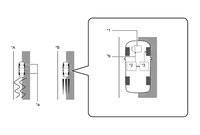
Text in Illustration *A Without TR(A)C *B With TR(A)C *1 Engine *2 ECM *3 Brake Actuator Assembly
- Skid Control ECU
- - *a Excessive drive force causes the drive wheels to slip *b Regulation of the throttle to control engine output 
Slippery Surface - -
-
-
Vehicle Stability Control (VSC)
-
The following 2 examples can be considered as circumstances in which the tires exceed their lateral grip limit. VSC is designed to help control the vehicle behavior by controlling the engine output and the brakes at each wheel when the vehicle is subject to one of the conditions indicated below.
Text in Illustration *a Understeer Tendency *b Oversteer Tendency -
To determine the condition of the vehicle, sensors detect the steering angle, vehicle speed, vehicle's yaw rate, and the vehicle's lateral acceleration, which are then calculated by the skid control ECU.
-
Whether or not the vehicle is experiencing understeer is determined by the difference between the target yaw rate and the vehicle's actual yaw rate. When the vehicle's actual yaw rate is smaller than the target yaw rate (a target yaw rate is determined based on the vehicle speed and steering angle) that should be generated when the driver operates the steering wheel, it means the vehicle is making a turn at a greater angle than the target locus of travel. Thus, the skid control ECU determines that there is a large understeer tendency.
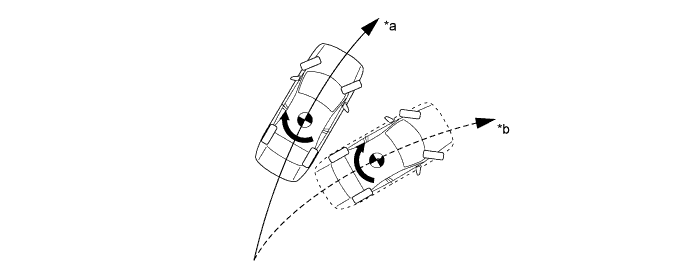
Text in Illustration *a Actual Locus of Travel (Actual Yaw Rate) *b Locus of Travel Based on the Target Yaw Rate -
Whether or not the vehicle is experiencing oversteer is determined by the values of the vehicle's slip angle and the vehicle's slip angular velocity (time-dependent changes in the vehicle's slip angle). When the vehicle's slip angle is large, and the slip angular velocity is also large, the skid control ECU determines that the vehicle has a large oversteer tendency.

Text in Illustration *a Slip Angle *b Direction of Travel of the Vehicle's Center of Gravity *c Movement of Vehicle - - -
When the skid control ECU determines that the vehicle exhibits a tendency to experience either understeer or oversteer, it decreases the engine output and applies the brakes of the front or rear wheels to control the vehicle's yaw moment. The basic operation of the VSC functions is described below. However, the control method differs depending on the vehicle's characteristics and driving conditions.
-
When the skid control ECU determines that there is a large understeer tendency, it takes countermeasures in accordance with the extent of that tendency. The skid control ECU controls the engine output and applies the brake of the front wheel and rear wheel of the inner circle of the turn in order to help restrain the understeer tendency
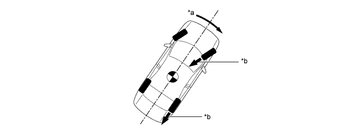
Text in Illustration (Making a Right Turn:) *a Control Moment *b Braking Force -
When the skid control ECU determines that there is a large oversteer tendency, it takes countermeasures in accordance with the extent of that tendency. It applies the brakes of the front wheel and rear wheel of the outer circle of the turn, and generates an outward moment of inertia in the vehicle, in order to restrain the oversteer tendency. Along with the reduction in the vehicle speed caused by the braking force, excellent vehicle stability is ensured.
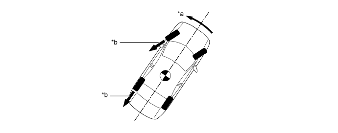
Text in Illustration (Making a Right Turn:) *a Control Moment *b Braking Force
-
-
-
FUNCTION
-
VSC OFF Switch
-
Using the VSC OFF switch can stop the operation of the VSC and TR(A)C functions. This is used to stop engine output control and maintain drive torque when driving on the shoulder or on dirt roads.
-
The VSC OFF switch can be used to select 3 modes (Normal mode, TR(A)C OFF mode, VSC OFF mode).
-
After the ignition switch is turned off in TR(A)C OFF mode or VSC OFF mode, turning the ignition switch to ON again selects normal mode.
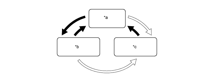
Text in Illustration *a Normal Mode *b TR(A)C OFF Mode *c VSC OFF Mode - - VSC OFF Switch Operation (Briefly Press) VSC OFF Switch Operation (Press and Hold for 3 Seconds or More) -
The operations of the brake control functions in each mode are as follows:
Mode Brake Control Function Combination Meter Assembly TR(A)C VSC TR(A)C OFF Indicator Light VSC OFF Indicator Light Normal Mode ○ ○ Does not illuminate Does not illuminate TR(A)C OFF Mode X ○ Illuminates Does not illuminate VSC OFF Mode X X* Illuminates Illuminates Tech Tips
○: Controllable
X: Not controllable
*: Control will be performed during braking.
-
-
-
CONSTRUCTION
-
Brake Actuator Assembly
-
The brake actuator assembly consists of the actuator portion and skid control ECU.
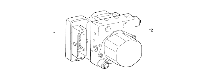
Text in Illustration *1 Skid Control ECU *2 Actuator Portion -
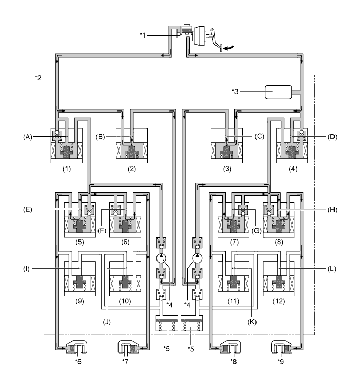
The actuator portion consists of 2 master cylinder cut solenoid valves, 2 reservoir cut solenoid valves, 4 pressure holding solenoid valves, 4 pressure reduction solenoid valves, 2 pumps, 2 reservoirs, and a master cylinder pressure sensor.
-
The brake actuator is constructed with the following hydraulic circuit:
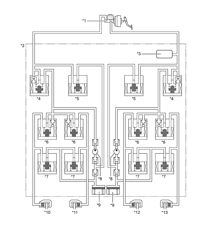
Text in Illustration *1 Brake Master Cylinder Sub-assembly *2 Brake Actuator Assembly *3 Master Cylinder Pressure Sensor *4 Master Cylinder Cut Solenoid Valve *5 Reservoir Cut Solenoid Valve *6 Pressure Holding Solenoid Valve *7 Pressure Reduction Solenoid Valve *8 Pump *9 Reservoir *10 Front Brake Caliper (Left Side) *11 Rear Brake Caliper (Right Side) *12 Rear Brake Caliper (Left Side) *13 Front Brake Caliper (Right Side) - -
-
-
Speed Sensor
-
An active type speed sensor is used. This sensor contains a sensor IC.
-
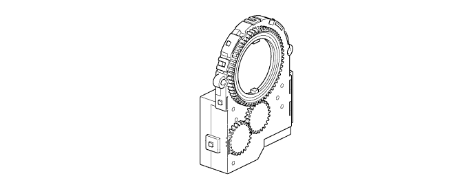
The front speed sensors use a gear type rotor that is mounted on the drive shaft.
-
The rear speed sensors use a magnet type sensor rotor, which consists of N and S poles that are arranged in a circle. The rear speed sensor rotor is integrated with the hub bearing inner race.
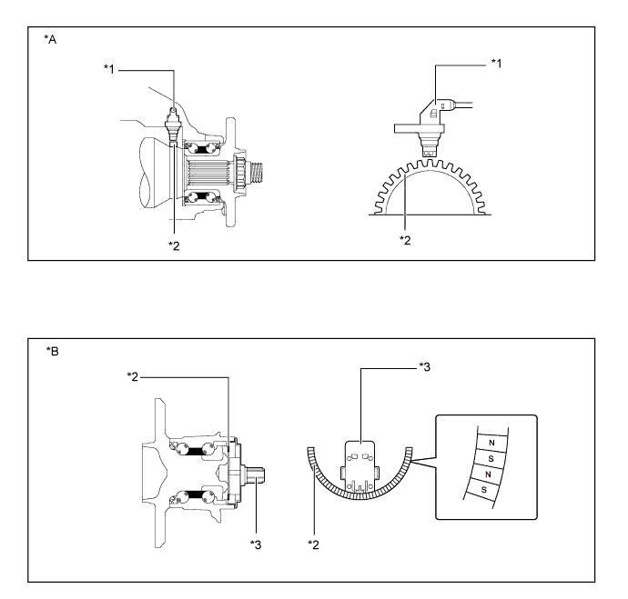
Text in Illustration *A Front *B Rear *1 Front Speed Sensor *2 Sensor Rotor *3 Rear Speed Sensor - - -
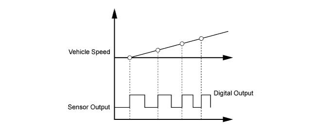
An active type speed sensor uses a sensor IC to detect magnetic field changes caused when the sensor rotor rotates, and the sensor outputs the detected information to the skid control ECU as digital pulses (vehicle speed signal).
-
To detect the vehicle speed, the frequency of the output pulses is used. Because the active type sensor outputs digital pulses, it can detect the vehicle speed even when the vehicle is nearly stationary.
-
-
Steering Sensor
-
The steering sensor detects the steering direction and angle, and sends this signal to the skid control ECU.
Tech Tips
When removing and reinstalling the steering sensor, it is necessary to use a special procedure to prevent the center position of the steering sensor from becoming misaligned. For details, refer to the Repair Manual.
-
-
Airbag Sensor Assembly
-
The airbag sensor assembly incorporates the acceleration sensor and yawrate sensor.
-
The yawrate sensor detects the vehicle's yaw rate.
-
The acceleration sensor detects the vehicle's longitudinal and lateral acceleration.
-
-
-
OPERATION
-
ABS and EBD
-
Based on the signals received from the 4 speed sensors and airbag sensor assembly, the skid control ECU calculates each wheel speed and deceleration, and checks wheel slipping conditions. According to the slipping condition, the skid control ECU controls the pressure holding solenoid valve and pressure reduction solenoid valve in order to adjust the fluid pressure of each wheel cylinder in the following 3 modes: pressure reduction, pressure holding, and pressure increase modes.
Not Activated Normal Braking - - Activated Increase Mode Holding Mode Reduction Mode Hydraulic Circuit 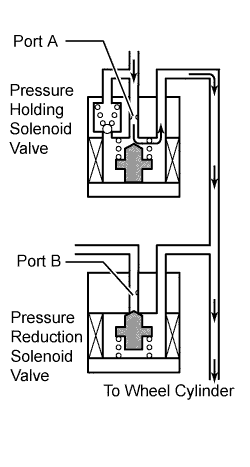
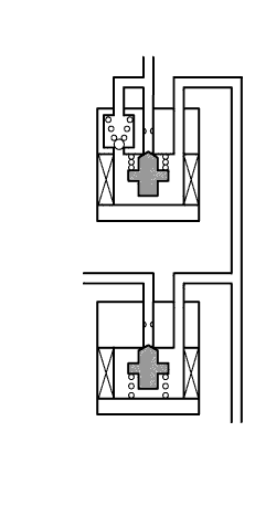
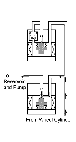
Pressure Holding Valve (Port A) OFF (Open) ON (Closed) ON (Closed) Pressure Reduction Valve (Port B) OFF (Closed) OFF (Closed) ON (Open) Brake Wheel Cylinder Pressure Increased Held Reduced
-
-
Brake Assist
-
In the event of emergency braking, the skid control ECU determines the driver's intentions based on the speed of the pressure increase in the master cylinder detected by the master cylinder pressure sensor signal. If the skid control ECU judges the need for additional brake assist, pressure to supplement the amount provided by the master cylinder is generated by the pump in the brake actuator and directed to each wheel cylinder.
-
The skid control ECU also provides brake assist in the event of a brake booster failure. The skid control ECU judges a brake booster failure using the brake load sensing switch and master cylinder pressure sensor signals.
Text in Illustration (Brake Assist Operation:) *1 Brake Master Cylinder Sub-assembly *2 Brake Actuator Assembly *3 Master Cylinder Pressure Sensor *4 Pump *5 Reservoir *6 Front Brake Caliper (Left Side) *7 Rear Brake Caliper (Right Side) *8 Rear Brake Caliper (Left Side) *9 Front Brake Caliper (Right Side) - - -
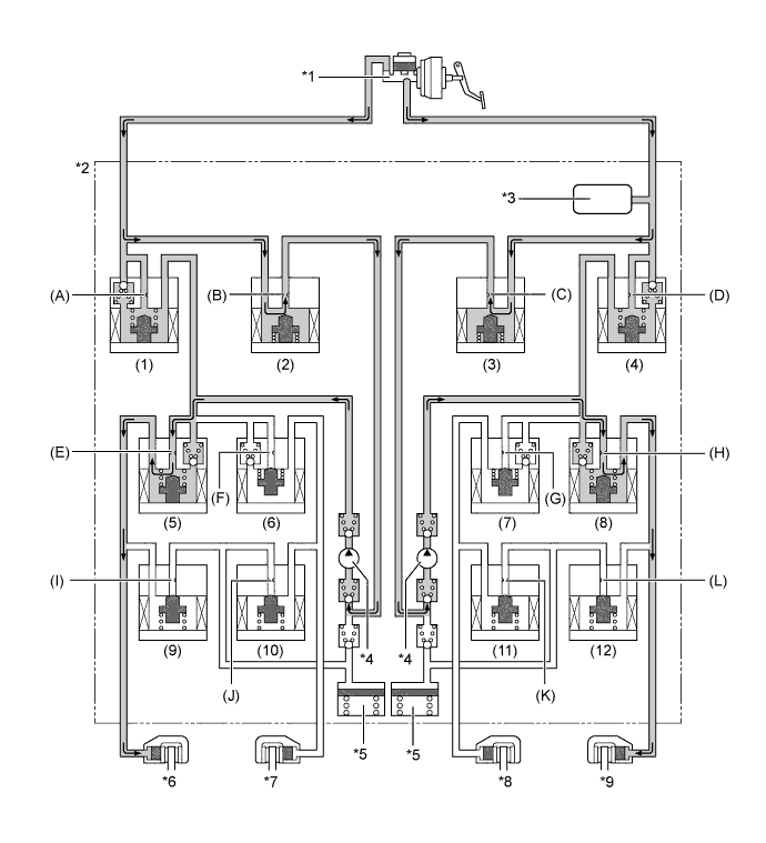
Each valve operates as shown below:
Item Port Brake Assist Not Activated Brake Assist Activated Master Cylinder Cut Solenoid Valves (1), (4) (A), (D) OFF (Open) ON* Reservoir Cut Solenoid Valve (2), (3) (B), (C) OFF (Closed) ON (Open) Front Brakes Pressure Holding Solenoid Valves (5), (8) (E), (H) OFF (Open) OFF (Open) Pressure Reduction Solenoid Valves (9), (12) (I), (L), OFF (Closed) OFF (Closed) Rear Brakes Pressure Holding Solenoid Valves (6), (7) (F), (G) OFF (Open) OFF (Open) Pressure Reduction Solenoid Valves (10), (11) (J), (K) OFF (Closed) OFF (Closed) Pump OFF ON *: Hydraulic pressure is controlled by continuously cycling the solenoid valves between open and closed, according to the operating conditions.
-
-
TR(A)C
-
The fluid pressure generated by the pump is regulated by the master cylinder cut solenoid valve to achieve the required pressure. Thus, the brakes for the drive wheels are controlled in the following 3 modes: pressure reduction, pressure holding, and pressure increase modes, to control slippage of the drive wheels.
-
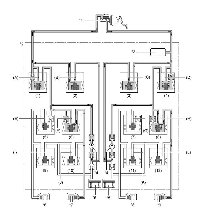
The diagram shows the hydraulic circuit in pressure increase mode when TR(A)C is activated. The pressure holding solenoid valve and the pressure reduction solenoid valve are turned ON/OFF according to the ABS and EBD operation pattern.
Text in Illustration (TR(A)C Operation:) *1 Brake Master Cylinder Sub-assembly *2 Brake Actuator Assembly *3 Master Cylinder Pressure Sensor *4 Pump *5 Reservoir *6 Front Brake Caliper (Left Side) *7 Rear Brake Caliper (Right Side) *8 Rear Brake Caliper (Left Side) *9 Front Brake Caliper (Right Side) - - -
Each valve operates as shown below:
Item Port TR(A)C Not Activated TR(A)C Activated Increase Mode Holding Mode Reduction Mode Master Cylinder Cut Solenoid Valve (1), (4) (A), (D) OFF (Open) ON* ON* ON* Reservoir Cut Solenoid Valve (2), (3) (B), (C) OFF (Closed) ON (Open) ON (Open) ON (Open) Front Brakes Pressure Holding Solenoid Valve (5), (8) (E), (H) OFF (Open) OFF (Open) ON (Closed) ON (Closed) Pressure Reduction Solenoid Valve (9), (12) (I), (L) OFF (Closed) OFF (Closed) OFF (Closed) ON (Open) Brake Wheel Cylinder Pressure - - - Increased Held Reduced Rear Brakes Pressure Holding Solenoid Valve (6), (7) (F), (G) OFF (Open) ON (Closed) ON (Closed) ON (Closed) Pressure Reduction Solenoid Valve (10), (11) (J), (K) OFF (Closed) OFF (Closed) OFF (Closed) OFF (Closed) Brake Wheel Cylinder Pressure - - - - - - Pump OFF ON ON ON *: Hydraulic pressure is controlled by continuously cycling the solenoid valves between open and closed, according to the operating conditions.
-
-
VSC
-
VSC, by way of solenoid valves, controls the fluid pressure generated by the pump and applies it to each wheel cylinder in the following 3 modes: pressure reduction, pressure holding, and pressure increase modes. As a result, understeer and oversteer tendencies are controlled.
-
In understeer restraining control, the skid control ECU controls engine output and applies the brakes of front and rear wheels on the inside of the turn. Also, depending on whether the brakes are applied and the vehicle condition, there are circumstances in which the brake of a specific wheel may not be applied even if it was targeted for braking. The diagram below shows the hydraulic circuit in pressure increase mode, as it restrains an understeer tendency while the vehicle is making a right turn. In other operating modes, the pressure holding valve and the pressure reduction valve are turned ON/OFF according to the ABS and EBD operation pattern.
Text in Illustration (VSC Operation (Understeer Restraining Control):) *1 Brake Master Cylinder Sub-assembly *2 Brake Actuator Assembly *3 Master Cylinder Pressure Sensor *4 Pump *5 Reservoir *6 Front Brake Caliper (Left Side) *7 Rear Brake Caliper (Right Side) *8 Rear Brake Caliper (Left Side) *9 Front Brake Caliper (Right Side) - - -
Each valve operates as shown below:
Item Port VSC Not Activated VSC Activated Increase Mode Holding Mode Reduction Mode Master Cylinder Cut Solenoid Valve (1), (4) (A), (D) OFF (Open) ON* ON* ON* Reservoir Cut Solenoid Valve (2), (3) (B), (C) OFF (Closed) ON (Open) ON (Open) ON (Open) Front Brakes Pressure Holding Solenoid Valve (5) (E) OFF (Open) ON (Closed) ON (Closed) ON (Closed) (8) (H) OFF (Open) OFF (Open) ON (Closed) ON (Closed) Pressure Reduction Solenoid Valve (9) (I) OFF (Closed) OFF (Closed) OFF (Closed) OFF (Closed) (12) (L) OFF (Closed) OFF (Closed) OFF (Closed) ON (Open) Brake Wheel Cylinder Pressure Right - - - Increased Held Reduced Left - - - - - - Rear Brakes Pressure Holding Solenoid Valve (6) (F) OFF (Open) OFF (Open) ON (Closed) ON (Closed) (7) (G) OFF (Open) ON (Closed) ON (Closed) ON (Closed) Pressure Reduction Solenoid Valve (10) (J) OFF (Closed) OFF (Closed) OFF (Closed) ON (Open) (11) (K) OFF (Closed) OFF (Closed) OFF (Closed) ON (Open) Brake Wheel Cylinder Pressure Right - - - Increased Held Reduced Left - - - - - - Pump OFF ON ON ON *: Hydraulic pressure is controlled by continuously cycling the solenoid valves between open and closed, according to the operating conditions.
-
In oversteer restraining control, the skid control ECU applies the brakes of the front and rear wheels on the outside of the turn. Also, depending on whether the brakes are applied and the vehicle condition, the brake of a specific wheel may not be applied even if it was targeted for braking. The diagram below shows the hydraulic circuit in pressure increase mode, as it restrains an oversteer tendency while the vehicle is making a right turn. In other operating modes, the pressure holding valve and the pressure reduction valve are turned ON/OFF according to the ABS and EBD operation patterns.

Text in Illustration (VSC Operation (Oversteer Restraining Control):) *1 Brake Master Cylinder Sub-assembly *2 Brake Actuator Assembly *3 Master Cylinder Pressure Sensor *4 Pump *5 Reservoir *6 Front Brake Caliper (Left Side) *7 Rear Brake Caliper (Right Side) *8 Rear Brake Caliper (Left Side) *9 Front Brake Caliper (Right Side) - - -
Each valve operates as shown below:
Item Port VSC Not Activated VSC Activated Increase Mode Holding Mode Reduction Mode Master Cylinder Cut Solenoid Valve (1), (4) (A), (D) OFF (Open) ON* ON* ON* Reservoir Cut Solenoid Valve (2), (3) (B), (C) OFF (Closed) ON (Open) ON (Open) ON (Open) Front Brakes Pressure Holding Solenoid Valve (5) (E) OFF (Open) OFF (Open) ON (Closed) ON (Closed) (8) (H) OFF (Open) ON (Closed) ON (Closed) ON (Closed) Pressure Reduction Solenoid Valve (9) (I) OFF (Closed) OFF (Closed) OFF (Closed) ON (Open) (12) (L) OFF (Closed) OFF (Closed) OFF (Closed) OFF (Closed) Brake Wheel Cylinder Pressure Right - - - - - - Left - - - Increased Held Reduced Rear Brakes Pressure Holding Solenoid Valve (6) (F) OFF (Open) ON (Closed) ON (Closed) ON (Closed) (7) (G) OFF (Open) OFF (Open) ON (Closed) ON (Closed) Pressure Reduction Solenoid Valve (10) (J) OFF (Closed) OFF (Closed) OFF (Closed) OFF (Closed) (11) (K) OFF (Closed) OFF (Closed) OFF (Closed) ON (Open) Brake Wheel Cylinder Pressure Right - - - - - - Left - - - Increased Held Reduced Pump OFF ON ON ON *: Hydraulic pressure is controlled by continuously cycling the solenoid valves between open and closed, according to the operating conditions.
-
-
-
FAIL-SAFE
-
If a failure occurs in the skid control ECU, sensors, or brake actuator assembly, the system continues performing brake control by excluding the failed area and using only the areas that are operating normally.
-
-
DIAGNOSIS
-
If the skid control ECU detects a malfunction in the brake control system, the warning lights or indicator light illuminate. At the same time, a Diagnostic Trouble Code (DTC) is stored in the memory of the skid control ECU.
-
This system has a sensor signal check (test mode) function.
-
For details of DTCs and the check function, refer to the Repair Manual.
-