FUEL SYSTEM GENERAL
-
OUTLINE
-
A compact 12-hole type fuel injector assembly is used to increase atomization of the fuel.
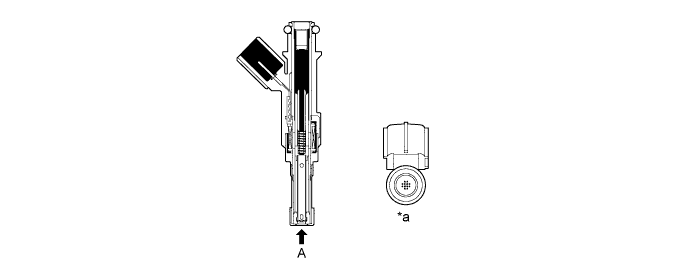
Text in Illustration *a View from A - - -
Quick connectors are used to connect the fuel pipes and fuel hoses for excellent serviceability.
-
A fuel returnless system is used to reduce evaporative emissions. As shown below, by integrating the fuel filter assembly, fuel pressure regulator assembly, and fuel pump, it is possible to discontinue the return of fuel from the engine area thus preventing temperature rise inside the fuel tank assembly. This reduces the generation of evaporative emissions in the fuel tank assembly.
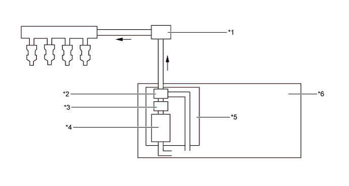
Text in Illustration *1 Fuel Pressure Pulsation Damper Assembly *2 Fuel Pressure Regulator Assembly *3 Fuel Filter Assembly *4 Fuel Pump *5 Fuel Suction Tube with Pump and Gauge Assembly *6 Fuel Tank Assembly -
A fuel delivery pipe sub-assembly made of steel is used.
-
Fuel cut control is used to stop the fuel pump if an SRS airbag is deployed in a frontal, side or rear side collision. For details, Click here.
-