LIGHTING SYSTEM DETAILS
-
FUNCTION OF MAIN COMPONENTS
-
Daytime Running Light System
Component Function Main Body ECU (Driver Side Junction Block Assembly) The main body ECU receives various signals and illuminates the low beam headlights*1, taillights*1, clearance lights*1 and license plate lights*1, or daytime running light*2. Headlight Dimmer Switch Assembly Light Control Switch The light control switch outputs a light control signal and transmits it to the main body ECU. ECM The ECM outputs an engine speed signal and transmits it to the main body ECU.
-
*:1 Models with halogen headlight
-
*:2 Models with Light Emitting Diode (LED) headlight
-
-
Automatic Light Control System
Component Function Main Body ECU (Driver Side Junction Block Assembly) The main body ECU receives various signals and illuminates the headlights, taillights, clearance lights, and license plate lights. Headlight Dimmer Switch Assembly Light Control Switch The light control switch transmits an AUTO position signal to the main body ECU. Light Control Sensor The light control sensor detects the ambient light level. -
LED Headlight System
Component Function Main Body ECU (Driver Side Junction Block Assembly) The main body ECU receives the HEAD position signal and transmits a signal to the light control ECU. Headlight Dimmer Switch Assembly Light Control Switch The light control switch transmits a HEAD position signal to the main body ECU. Headlight Unit LED Driver Module (Light Control ECU) The LED driver module (light control ECU) applies battery voltage to LEDs in order to illuminate them. Light Emitting Diode (LED) The LED shines ahead over a broader area and further forward, increasing the area visible to the driver. -
Automatic Headlight Beam Level Control System
Component Function Headlight Swivel ECU Assembly The headlight swivel ECU assembly receives various signals, calculates the target lighting angle, and actuates the headlight leveling motor. Headlight Unit Headlight Leveling Motor
-
Based on the signals received from the headlight swivel ECU assembly, the motors move the reflectors in the headlights.
-
Uses a step motor to precisely regulate the angle of the reflectors.
Rear Height Control Sensor Sub-assembly RH Detects the height of the vehicle. Skid Control ECU Transmits the front speed sensor signal to the headlight swivel ECU assembly. ECM Transmits the engine running status signal to the headlight swivel ECU assembly. Main Body ECU (Driver Side Junction Block Assembly) Transmits the headlight swivel ECU assembly. Combination Meter Assembly Headlight Leveling Indicator Light If the system malfunctions, the meter ECU alerts the driver by the headlight leveling indicator light in accordance with the signal from the headlight swivel ECU assembly. -
-
Emergency Brake Signal
Component Function Skid Control ECU Manages signals from each sensor and sends the operation signal of the emergency brake signal to the stop light control ECU assembly. Yaw Rate Sensor Detects vehicle acceleration and sends the information to the skid control ECU. Speed Sensor Detects the wheel speed of each of the 4 wheels. Stop Light Switch Assembly Detects the brake pedal depressing signal. Hazard Warning Signal Switch Assembly Sends the operation signal of the hazard warning light to the skid control ECU and the hazard warning light. Hazard Warning Light Blinks when a signal is received from the hazard warning signal switch assembly. Stop Light Control ECU Assembly The stop light and high mount stop light are made to blink in accordance with the hazard warning light and the operation signal of the emergency brake signal from the skid control ECU. Rear Combination Light Assembly Stop Light Blinks when a signal is received from the stop light control ECU assembly. High Mount Stop Light
-
-
OPERATING CONDITION
-
Daytime Running Light System
-
Daytime running light system is enabled when the conditions given below are met:
Condition Ignition switch is ON. Light control switch OFF or AUTO position (when the taillights are is not being controlled by the automatic light control). Engine is running. Parking brake is not engaged.
-
-
Light Automatic Turn-off System
-
The light automatic turn-off system performs when the following conditions are met:
Function Destination Light Control Switch Position Condition Without Turn-off Delay ALL Except OFF All lights will be turned off if the following condition is met while the lights (headlights, front fog lights*1, rear fog lights*2 and taillights) are turned on:
-
The ignition switch is turned from ON to off and the driver door is open.
With Turn-off Delay Europe AUTO All lights will be turned off after 30 seconds if the following condition is met while the lights (headlights, front fog lights*1, rear fog lights*2 and taillights) are turned on:
-
The ignition switch is turned from ON to off and any of all doors, back door and glass hatch is open.
HEAD or TAIL The headlights and front fog lights will be turned off if the following condition is met while the lights (headlights, front fog lights*1, rear fog lights*2 and taillights) are turned on:
-
The ignition switch is turned from ON to off.
Except Europe AUTO or TAIL All lights will be turned off if the following condition is met while the taillights are turned on:
-
The ignition switch is turned from ON to off and the driver door is open.
AUTO or HEAD All lights will be turned off after 30 seconds if the following condition is met while the headlights are turned on:
-
The ignition switch is turned from ON to off and any of all doors, back door and glass hatch is open and closed.
-
*1: Models with front fog light
-
*2: Models with rear fog light
-
-
-
-
FUNCTION
-
Light Emitting Diode (LED) Headlight System
-
The LED headlight system consists of LEDs and light control ECUs.
-
A fail-safe function is provided when a problem occurs in the headlight system.
-
-
Automatic Headlight Beam Level Control System
-
The automatic headlight beam level control system mainly consists of the headlight swivel ECU assembly, rear height control sensor, and 2 headlight leveling motors.
-
The headlight swivel ECU assembly calculates changes in the vehicle posture based on the signals from the rear height control sensor sub-assembly RH.
-
The ECU controls the headlight leveling motor based on this information in order to change the headlight reflector angle.
-
Initial Set Control
-
When the engine is started, the headlight swivel ECU assembly drives the headlight leveling motor, moves the headlight reflector to the lower limit position and returns it to the proper position. The headlight swivel ECU assembly thus assesses the position of the headlight for reference control.
-
-
-
-
CONSTRUCTION
-
LED Driver Module (Light Control ECU)
-
When the headlights are turned on, the LED driver modules immediately turn on the LEDs (approximately 0.1 seconds). In addition, by regulating the output current flowing into the LEDs at a specified level, the LED driver modules prevent the light from becoming brighter and dimming due to voltage variation.
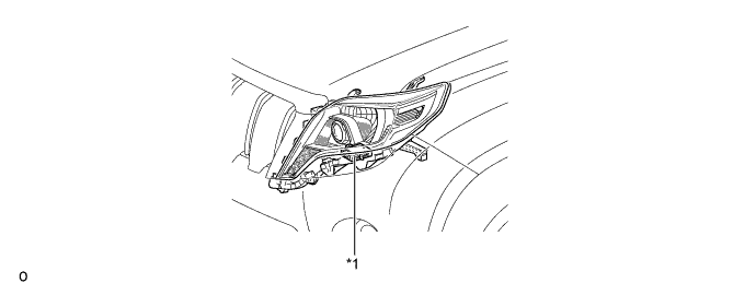
Text in Illustration *1 LED Driver Module (Light Control ECU) - - -
If malfunctions occur in an LED headlight system, the LED driver module transmits fail signals to the headlight swivel ECU. When the headlight swivel ECU receives the fail signals, it transmits signals to the combination meter assembly to warn the driver.
-
The combination meter assembly warns the driver by indicating a message on the multi-information display, sounding the buzzer and illuminating the master warning light when signals are received from the headlight swivel ECU assembly.
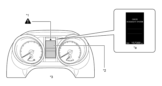
Text in Illustration *1 Master Warning Light *2 Multi-information Display *3 Combination Meter Assembly - - *a Warning Message - -
-
-
-
OPERATION
-
Emergency Brake Signal
-
The operating and ending conditions for the emergency brake signal are listed below. When the emergency brake signal operates, the skid control ECU causes the stop light control ECU assembly to blink the stop lights. When the emergency brake signal ends, the skid control ECU causes the stop light control ECU assembly to end the blinking of the stop lights.
Emergency Brake Signal Operating Condition Activates when all of the following conditions are satisfied:
-
The vehicle speed is 55 km/h (34 mph) or more.
-
The system judges from a depression of the brake pedal and a drop in vehicle speed that emergency braking is occurring.
Emergency Brake Signal Ending Conditions Stops the operation when any of the following conditions is met:
-
The system judges from the vehicle's deceleration that no emergency braking is occurring.
-
The hazard warning light is blinking.
-
The brake pedal is released.
-
-
-
-
FAIL-SAFE
-
Light Emitting Diode (LED) Headlight System
-
The LED driver module (light control ECU) executes the fail-safe actions listed below in accordance with the problem that has been detected:
Problem Outline Detection of Abnormal Input Voltage If the voltage input to the LED driver module deviates from the normal operating voltage (10 V to 16 V), the LED driver module stops illuminating the headlights. It resumes illuminating the headlights once the voltage reverts to the operating voltage range. However, if the input voltage decreases after the headlights have illuminated, the headlights will remain illuminated until the input voltage is insufficient to light the LEDs. Detection of Abnormal Output (Open Circuit or Short Circuit) If an abnormal condition (open or short) occurs in the voltage that is output by the LED driver module, the LED driver module stops illuminating the headlights and will maintain this state until the power is reinstated. Power is reinstated by turning the light control switch from off to on.
-
-
Automatic Headlight Beam Level Control System
-
If the headlight swivel ECU assembly detects a malfunction in the automatic headlight beam level control system, it will take the actions indicated in the table below:
Trouble Area Condition (Fail-safe Control for Automatic Headlight Beam Level Control) Headlight Leveling Indicator Light Speed Sensor Signal Malfunction Continues to control Illuminates Height Control Sensor Signal Malfunction
-
Stops the operation after returning to initial position (fails at higher than initial position).
-
Stops the operation in current condition (fails at lower than initial position).
Illuminates Headlight Leveling Motor Malfunction Normal Side Headlight Leveling Motor:
-
Stops the operation after returning to initial position (fails at higher than initial position).
-
Stops in current condition (fails at lower than initial position).
Illuminates Abnormal Side Headlight Leveling Motor:
-
Stops in its current position.
Illuminates Communication Signal Malfunction Continues to control. Illuminates -
-
-
-
DIAGNOSIS
-
Automatic Headlight Beam Level Control System
-
If the headlight swivel ECU assembly detects a malfunction in the automatic headlight beam level control system, the headlight swivel ECU assembly illuminates the headlight leveling indicator light. At the same time, the Diagnostic Trouble Codes (DTCs) are stored in memory. The DTCs can be read by use of the Global TechStream (GTS). For details, refer to the Repair Manual.
-
-