TOYOTA PARKING ASSIST-SENSOR SYSTEM DETAILS
-
FUNCTION OF MAIN COMPONENTS
-
The components have the following functions:
Component Function Ultrasonic Sensors Detects the distance between the vehicle and the obstacle. Clearance Warning ECU Assembly
-
Judges the approximate distance between the vehicle and obstacle based on the signals from the ultrasonic sensors and sends the buzzer signal to the clearance warning buzzer assembly.
-
Transmits signals to the clearance warning indicator assembly.*1
-
Receives signals from switch operation and the ECU, and displays a clearance warning icon on the combination meter assembly, the radio and display receiver assembly*2 and the navigation receiver assembly*3.*4
Clearance Warning Buzzer Assembly Sounds intermittently to inform the driver that the clearance warning ECU assembly has detected an obstacle within the prescribed range. Multi-information Switch*8 The TOYOTA parking assist-sensor system can be turned on or off by operating this switch. Back Sonar or Clearance Sonar Switch Assembly*1 Turns the TOYOTA parking assist-sensor system on/off. Combination Meter Assembly
-
Transmits received vehicle speed signals to the clearance warning ECU assembly.
-
Displays the detection location on the multi-information display when an obstacle is detected.*8
Radio and Display Receiver Assembly*2 or Navigation Receiver Assembly*3 Displays the detection location on the multi-display when an obstacle is detected. Clearance Warning Indicator Assembly*1 Flashes the indicator light of the detected area when an obstacle is detected. Back-up Light Switch Assembly*5 Transmits the on/off signals of the back-up light switch assembly to the ECM. Air Conditioning Amplifier Assembly Transmits the outside air temperature to the clearance warning ECU assembly. Park/Neutral Position Switch Assembly*6 Transmits the R position signal to the ECM or the TCM*7. TCM*7 Transmits shift position signals to the ECM. ECM Transmits shift position signals from the back-up light switch assembly or park/neutral position switch assembly or TCM*7 to the clearance warning ECU assembly.
-
*1: Models with clearance warning indicator assembly
-
*2: Models with display audio system
-
*3: Models with navigation system
-
*4: Models without clearance warning indicator assembly
-
*5: Models with manual transmission
-
*6: Models with automatic transmission
-
*7: Models with 1KD-FTV engine and automatic transmission
-
*8: Models with Optitron display type combination meter assembly
-
-
-
OPERATING CONDITION
-
The operating condition of each ultrasonic sensor differs in accordance with its installed position as shown in the table below:
Installation Position Operating Condition Front Corner*
-
Ignition switch is ON.
-
TOYOTA parking assist-sensor system is on.
-
Shift lever is in any position except P.
-
Vehicle speed is approximately 10 km/h (6 mph) or less.
Front Center*
-
Ignition switch is ON.
-
TOYOTA parking assist-sensor system is on.
-
Shift lever is in any position except P and R.
-
Vehicle speed is approximately 10 km/h (6 mph) or less.
Rear Center or Corner
-
Ignition switch is ON.
-
TOYOTA parking assist-sensor system is on.
-
Shift lever is in R.
-
*: Models with 8-sensor type TOYOTA parking assist-sensor system
-
-
-
CONSTRUCTION
-
Ultrasonic Sensor
-
The ultrasonic sensor consists of a circuit portion and a microphone that transmits and receives ultrasonic waves.
-
The circuit portion is filled with urethane to prevent water from entering.
-
The shape of each sensor is identical.

-
-
Clearance Warning Buzzer Assembly
-
When the ultrasonic sensor transmits ultrasonic waves and receives the reflected waves from an obstacle, the buzzer sounds in stages in accordance with the distance to the obstacle.

-
-
Clearance Warning ECU Assembly
-
The clearance warning ECU assembly effects overall control of the system, including switching between transmission and reception of the ultrasonic sensor signals, processing the received wave signals, determining the presence of obstacles, actuating the clearance warning buzzer assembly, and determining the presence of an open circuit in the sensors.
-
-
Clearance Warning Indicator Assembly (Models with Clearance Warning Indicator Assembly)
-
The driver is informed that there is an obstacle nearby by the flashing of the clearance warning indicator assembly located on the instrument panel. Also, the clearance warning buzzer assembly sounds simultaneously.
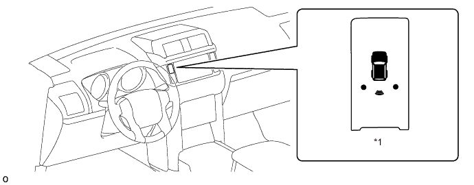
Text in Illustration *1 Clearance Warning Indicator Assembly - -
-
-
-
OPERATION
-
The on and off times of the clearance warning buzzer assembly vary as shown in the table below, depending on the distance between the obstacle and the ultrasonic sensor.
Front Ultrasonic Sensor* - Obstacle Distance [mm (in.)] Off Time (ms) On Time (ms) Detection Area A B Ultrasonic Sensor Centers Corners Detection Level 1st Approx. 600 (23.6) to 1000 (39.4) - 650 150 2nd Approx. 450 (17.7) to 600 (23.6) Approx. 400 (15.7) to 500 (19.7) 150 150 3rd Approx. 300 (11.8) to 450 (17.7) Approx. 300 (11.8) to 400 (15.7) 75 75 4th Approx. 300 (11.8) or less Approx. 300 (11.8) or less 0 Continuous
-
*: Models with 8-sensor type TOYOTA parking assist-sensor system
Rear Ultrasonic Sensor - Obstacle Distance [mm (in.)] Off Time (ms) On Time (ms) Detection Area C D Ultrasonic Sensor Centers Corners Detection Level 1st Approx. 650 (25.6) to 1500 (59.0) - 650 150 2nd Approx. 500 (19.7) to 650 (25.6) Approx. 375 (14.8) to 550 (21.7) 150 150 3rd Approx. 400 (15.7) to 500 (19.7) Approx. 250 (9.8) to 375 (14.8) 75 75 4th Approx. 400 (15.7) or less Approx. 250 (9.8) or less 0 Continuous 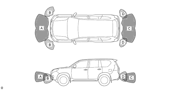
-
-
Multi-information Display (Models with Optitron Display Type Combination Meter Assembly)
-
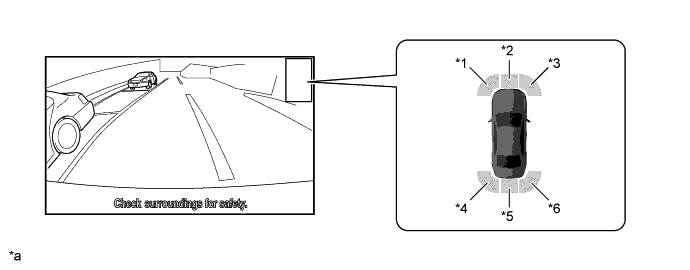
The location of an obstacle and the approximate distance between the vehicle and the obstacle are displayed on the multi-information display.
-
The number of lines shown on the display changes based on the actual distance and flashes when the distance is short.
-
The distance is displayed by the number of lines and color based on the actual distance. The display usually illuminates in yellow. When the distance is short, it illuminates in red.
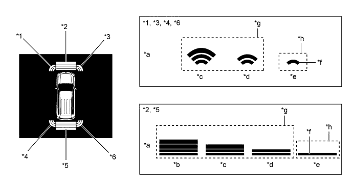
Text in Illustration *1 Front Corner LH *2 Front Center *3 Front Corner RH *4 Rear Corner LH *5 Rear Center *6 Rear Corner RH *a Distance *b Longest *c Long *d Middle *e Short *f Flashes *g Yellow *h Red -
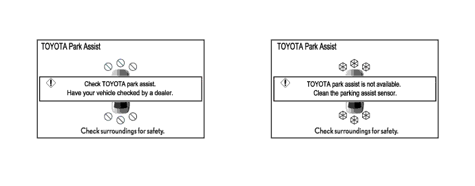
Screens displaying warning messages relating to an ultrasonic sensor malfunction, ultrasonic sensor freezing, or presence of foreign matter on the ultrasonic sensor are displayed on the multi-information display.
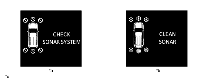
Text in Illustration *a Malfunctioning *b Frozen/Dirty *c The illustrations shown are examples only. The illustrations may differ from the actual vehicle screens. - -
-
-
Multi-display (Models without Clearance Warning Indicator Assembly)
-
The location of an obstacle and the approximate distance between the vehicle and the obstacle are displayed on the multi-display.
-
The distance is displayed by the number of lines and color based on the actual distance. The display usually illuminates in yellow. When the distance is short, it illuminates in red.
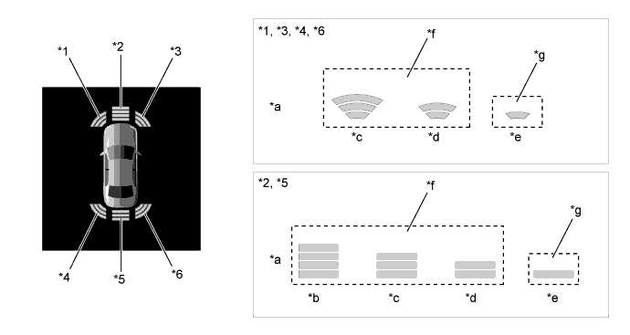
Text in Illustration *1 Front Corner LH *2 Front Center *3 Front Corner RH *4 Rear Corner LH *5 Rear Center *6 Rear Corner RH *a Distance *b Longest *c Long *d Middle *e Short *f Yellow *g Red - - -
If an obstacle is detected when the monitor system, parking assist monitor system or multi-terrain monitor system is activated, the approximate distance between the vehicle and the obstacle is displayed on the multi-display.
-
The distance is displayed by color based on the actual distance to the obstacle. When an obstacle is detected at the long or middle distance, the indicator is yellow. The color changes from yellow to red when the distance becomes short.
Text in Illustration *1 Front Corner LH *2 Front Center *3 Front Corner RH *4 Rear Corner LH *5 Rear Center *6 Rear Corner RH *a The illustrations shown are examples only. The illustrations may differ from the actual vehicle screens. - - -
Screens displaying warning messages relating to an ultrasonic sensor malfunction, ultrasonic sensor freezing, or presence of foreign matter on the ultrasonic sensor are displayed on the multi-display.
-
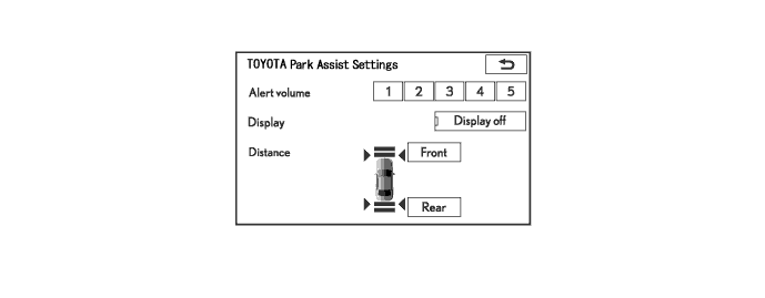
The display timing and detection distance can be customized using the multi-display.
-
-
-
DIAGNOSIS
-
If the system cannot activate its detection function due to a malfunction in an ultrasonic sensor, it alerts the driver of the malfunction by the sounding the clearance warning buzzer assembly. For details, refer to the Repair Manual.
-