POWER STEERING SYSTEM DETAILS
-
FUNCTION OF MAIN COMPONENTS
Component Function Rack and Pinion Power Steering Gear Assembly Increases operation force of the steering wheel and transmits operation force to the front wheel. Vane Pump Assembly Pumps power steering fluid to the steering gear assembly. VFC Solenoid Valve*1
(Built into Vane Pump Assembly)
Controls the discharge flow rate and is controlled by the power steering ECU assembly. Vane Pump Oil Reservoir Stores the power steering fluid. Combination Meter Assembly
-
Power Steering Warning Light*1
Lights up to alert the driver that the power steering ECU assembly has detected a malfunction in the power steering system. Steering Angle Sensor Detects the steering direction and the angle of the steering wheel. Absorber Control Switch*2 Switches the damping force control mode. Power Steering ECU Assembly*1 Calculates the optimum discharge flow rate in accordance with the vehicle condition, and controls the VFC solenoid valve. Skid Control ECU Sends the vehicle speed signal. ECM Sends the engine speed signal. Suspension Control ECU*2 Sends the damping force control signal. 4WD Control ECU Sends the transfer drive mode signal.
-
*1: Models with VFC
-
*2: Models with AVS
-
-
SYSTEM CONTROL
-
The Variable Flow Control (VFC) power steering optimizes the discharge rate of the power steering fluid sent from the vane pump based on the vehicle speed, steering speed, steering angle and engine speed. There are 3 types of discharge rate control: basic control, L4 range control and AVS cooperative control.
-
The basic control includes standby control and assist control. When the steering wheel is not operated such as while driving straight, standby control is performed. The moment the steering wheel is operated, standby control switches to assist control. Also, steering angle correction is performed to gradually reduce the discharge rate based on the vehicle speed and steering angle.
-
Under standby control, the discharge rate is maintained in order to suppress the drive torque of the vane pump and help improve fuel efficiency.
-
Under assist control, the discharge rate is increased when the steering wheel is operated at low speeds in order to reduce steering force. On the other hand, the discharge rate is reduced when the steering wheel is operated at high speeds in order to maintain a solid steering force.
-
Under L4 range control, control characteristics that limit variations in the discharge rate due to changes in steering speed and vehicle speed are used in order to determine the ground conditions between the tires and the road surface during off-road driving.
-
On models with an AVS, optimal discharge rate control is performed depending on the damping force control mode.
-
Basic Control
-
The power steering ECU assembly switches between standby control and assist control depending on the vehicle speed, steering speed and steering angle.
-
Under assist control, the discharge rate is determined based on the vehicle speed and steering speed.
-
The discharge rate is then adjusted in response to the steering angle.
Control Function Outline Standby Control
(Assist Control → Standby Control)
The steering speed is 0 deg/sec for 0.01 seconds or more when the vehicle speed is 0 km/h. The discharge rate decreases at a rate of 0.5 l/min.
(The discharge rate may increase depending on the steering conditions.)
The steering angle is less than 4.5° for 0.01 seconds or more except when the vehicle speed is 0 km/h. Assist Control
(Standby Control → Assist Control)
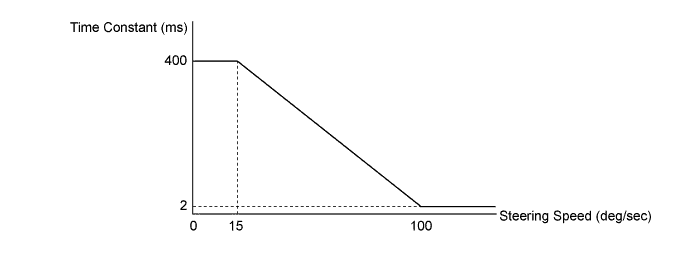
The steering speed is 0 deg/sec or more when the vehicle speed is 0 km/h. This control increases the discharge rate according to the steering speed when the time constant reaches a certain value.
(The discharge rate may also be reduced depending on the steering conditions when the time constant reaches a certain value.)
The steering angle is 4.5° or more except when the vehicle speed is 0 km/h. Tech Tips
*: The time constant is the amount of time required for the power steering fluid to reach a target discharge rate of 63.2%.
-
-
L4 Range Control
-
In off-road driving, the steering force amount is important information for understanding the condition of the contact between the tire and the road. Accordingly, this system has the control feature of allowing the discharge flow rate to change as little as possible in accordance with the vehicle speed and steering speed when in transfer drive mode L4F or L4L.
-
-
AVS Cooperative Control
-
By optimizing the discharge rate control based on the status of the AVS damping force control mode, the steering conditions of the vehicle are easily conveyed to the driver, achieving improved steering feel and a sense of unity between the vehicle and driver.
-
When the damping force control SPORT mode is selected, the discharge rate of the power steering fluid sent from the vane pump is reduced and the steering feel will become heavier than that of COMFORT mode and NORMAL mode, producing a steering feel suitable for a sporty drive.
-
-
-
-
CONSTRUCTION
-
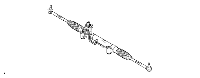
Rack and Pinion Power Steering Gear Assembly
-
Operability has been improved through a lightweight, compact rack and pinion type steering gear assembly.
-
A variable gear ratio type steering rack is used. This steering rack changes the gear ratio gradually by changing the form of the gear teeth. The gear ratio is set larger around the steering center and smaller around the end position. Thus, rack stroke around the end position is larger to reduce the steering operation while ensuring moderate response around the steering center.
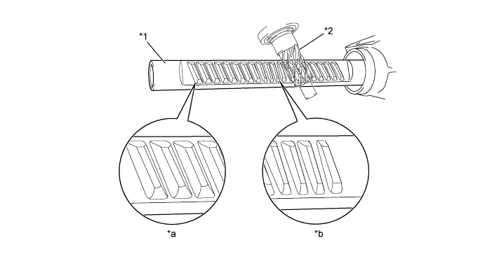
Text in Illustration *1 Rack *2 Pinion Gear *a Steering End Position *b Steering Center Position
-
-
Vane Pump Assembly
-
A compact and lightweight vane pump is used.
-
A VFC solenoid valve is provided to control the discharge flow rate (on models with a 2TR-FE, 1GR-FE or 1KD-FTV engine).
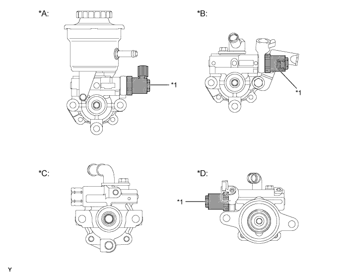
Text in Illustration *A Models with 2TR-FE Engine *B Models with 1GR-FE Engine *C Models with 5L-E Engine *D Models with 1KD-FTV Engine *1 VFC Solenoid Valve - - 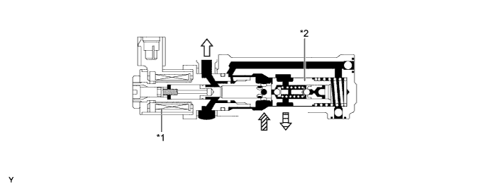
Text in Illustration (VFC Solenoid Valve) *1 VFC Solenoid Valve *2 Flow Control Valve 
To Rack and Pinion Power Steering Gear 
From Vane Pump 
To Vane Pump - - 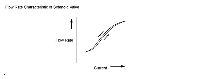
-
-
-
FAIL-SAFE
-
If the power steering ECU detects a malfunction in the power steering system, it illuminates the power steering warning light to alert the driver of the malfunction.
-
If a malfunction occurs in any of the sensors, the power steering ECU prevents standby control and performs the following fail-safe control:
Fail-safe Control List Malfunction Fail-safe Control Steering Angle Signal
-
Fixes the steering angle to 0°
-
Fixes the steering speed to 360 deg/sec
-
Steering angle correction is canceled
Steering Zero Point Memory
-
Fixes the steering angle to 0°
-
Steering angle correction is canceled
Vehicle Speed Signal
-
Fixes the vehicle speed to 40 km/h (24.9 mph)
Steering Angle Signal and Steering Zero Point Memory
-
Fixes the steering angle to 0°
-
Fixes the steering speed to 360 deg/sec
-
Steering angle correction is canceled
Steering Angle Signal and Vehicle Speed Signal
-
Fixes the steering angle to 0°
-
Fixes the steering speed to 360 deg/sec
-
Fixes the vehicle speed to 40 km/h (24.9 mph)
-
Fixes the discharge flow rate to 8.5 l/min
Steering Zero Point Memory and Vehicle Speed Signal
-
Fixes the steering angle to 0°
-
Fixes the vehicle speed to 40 km/h (24.9 mph)
-
Steering angle correction is canceled
Steering Angle Signal, Steering Zero Point Memory and Vehicle Speed Signal
-
Fixes the steering angle to 0°
-
Fixes the steering speed to 360 deg/sec
-
Fixes the vehicle speed to 40 km/h (24.9 mph)
-
Fixes the discharge flow rate to 8.5 l/min
-
-
-
DIAGNOSIS
-
If the power steering ECU detects a malfunction in the VFC power steering system, the power steering warning light will illuminate to inform the driver.
-
At the same time, the Diagnostic Trouble Codes (DTCs) are stored in memory. The DTCs stored in the power steering ECU are output to a Global TechStream (GTS) connected to the DLC3. For details, refer to the Repair Manual.
-