BRAKE CONTROL SYSTEM (for Hydraulic Brake Booster) DETAILS
-
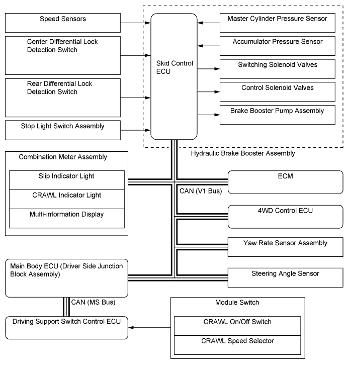
FUNCTION OF MAIN COMPONENTS
Component Function Combination Meter Assembly Brake System Warning Light
-
Lights up to alert the driver when the skid control ECU detects a malfunction in the EBD.
-
Lights up to alert the driver when the brake fluid level is low.
-
Lights up to alert the driver that the hydraulic pressure of the brake booster accumulator assembly in the hydraulic brake booster assembly has decreased.
-
Lights up to inform the driver of the parking brake condition.
ABS Warning Light Lights up to alert the driver when the skid control ECU detects a malfunction in the ABS or multi-terrain ABS. Slip Indicator Light Blinks to inform the driver when the TRC, A-TRC, VSC, trailer sway control, hill-start assist control, downhill assist control and CRAWL are operational. TRC OFF Indicator Light Lights up to inform the driver that the TRC OFF mode has been entered using the VSC OFF switch. VSC OFF Indicator Light Lights up to inform the driver that the VSC OFF mode has been entered using the VSC OFF switch. Downhill Assist Control Indicator Light*1 Lights up to inform the driver that the downhill assist control switch has been turned on. CRAWL Indicator Light*2 Lights up to inform the driver that the CRAWL on/off switch has been turned on. Multi-terrain Select Indicator Light*2 Lights up to inform the driver that multi-terrain select control is available. Multi-information Display*3
-
Displays multi-terrain select operation assist messages.
-
Displays multi-terrain select road mode.
-
Informs the driver of the status of the CRAWL operation.
Master Warning Light*3 Lights up and sounds the buzzer in the combination meter assembly to inform the driver that CRAWL control has been released. Multi Buzzer Sounds to inform the driver that a malfunction has occurred in the hydraulic brake booster assembly. Speed Sensor Detects the wheel speed of each of the 4 wheels. Yaw Rate Sensor Assembly
(with Built-in Deceleration Sensor)
-
Detects the vehicle's longitudinal and lateral acceleration.
-
Detects the vehicle's yaw rate.
Steering Angle Sensor Detects the direction and angle of the steering wheel. Stop Light Switch Assembly Detects the brake pedal depressing signal. Parking Brake Switch Assembly Detects that the parking brake lever is pulled up. Center Differential Lock Detection Switch
(Built into Transfer Shift Actuator Assembly)
Detects the center differential lock condition. Rear Differential Lock Detection Switch*2 Detects the rear differential lock condition. VSC OFF Switch Enables the driver to select "Normal Mode", "TRC OFF Mode", or "VSC OFF Mode". Module Switch*2 Multi-terrain Select Switch Turns the multi-terrain select on and off. Multi-terrain Select Road Mode Selector Selects multi-terrain select road mode. CRAWL On/Off Switch Turns the CRAWL on and off. CRAWL Speed Selector Used to select the target vehicle speed when the CRAWL is active. Downhill Assist Control Switch*1 Turns the downhill assist control on and off. Hydraulic Brake Booster Assembly Actuator Portion Changes the brake fluid path based on the signals from the skid control ECU during the operations of the brake control functions in order to control the fluid pressure that is applied to the wheel cylinders. Brake Fluid Level Warning Switch Detects that the brake fluid level is low. Master Cylinder Pressure Sensor Detects the master cylinder pressure and outputs this information to the skid control ECU. Accumulator Pressure Sensor Monitors the hydraulic pressure of the brake booster accumulator assembly and outputs this information to the brake booster pump assembly control. Control Pressure Sensor*4 In the brake control of the pre-crash safety system, hydraulic pressure is applied from the brake booster accumulator assembly to each wheel cylinder, generating braking force automatically. The control pressure sensor detects the control hydraulic pressure at that time. Switching Solenoid Valve Switches the brake hydraulic path when the brake control system is activated. Control Solenoid Valve Controls the hydraulic pressure that is applied to the wheel cylinders during brake control. Brake Booster Pump Assembly Draws up the brake fluid from the brake master cylinder reservoir and provides high hydraulic pressure to the brake booster accumulator assembly. Skid Control ECU Judges the vehicle driving condition based on signals from each sensor, and sends brake control signals to the hydraulic brake booster assembly. 4WD Control ECU Sends the transfer drive mode. ECM
-
Sends the throttle position signal, accelerator pedal position signal, engine speed signal etc., to the skid control ECU.
-
Based on the signals received from the skid control ECU, controls the engine output.
-
*1: Models without manual transmission and multi-terrain select
-
*2: Models with multi-terrain select
-
*3: Models with Optitron display type combination meter assembly
-
*4: Models with dynamic radar cruise control system
-
-
OPERATING CONDITION
-
The brake control function varies by the transfer drive mode as shown in the following table:
Models without Multi-terrain Select Brake Control Function Transfer Drive Mode H4F H4L L4F L4L ABS ○ ○ ○ ○ EBD ○ ○ ○ ○ Brake Assist ○ ○ ○ ○ TRC ○ ○ X X A-TRC X X ○ ○ VSC ○ ○ ○ X Trailer Sway Control ○ ○ ○ X Hill-start Assist Control ○ ○ ○ ○ Downhill Assist Control X X ○ ○ Tech Tips
○: Operates
X: Does not operate
Models with Multi-terrain Select Brake Control Function Transfer Drive Mode H4F H4L L4F L4L Rear Differential Lock On ABS/Multi-terrain ABS ○ ○ ○ ○ X EBD ○ ○ ○ ○ ○ Brake Assist ○ ○ ○ ○ X TRC ○ ○ X X X A-TRC ○* ○* ○* ○* ○* VSC ○ ○ ○ X X Trailer Sway Control ○ ○ ○ X X Hill-start Assist Control ○ ○ ○ ○ X CRAWL X X ○ ○ ○ Tech Tips
○: Operates
X: Does not operate
*: When the multi-terrain select is on
-
Hill-start Assist Control
-
The hill-start assist control operates when all of the following conditions have been met:
Hill-start Assist Control Operation Condition - The shift lever is in D or S.
- The brake pedal is not depressed.
- The rear differential lock switch is off.
- The skid control ECU has detected the backward movement of the vehicle when the driver is starting off on a hill.
-
The hill-start assist control stops operating when any of the following conditions have been met:
Hill-start Assist Control Ending Condition - The shift lever is in any position other than D or S.
- The brake pedal is depressed.
- The rear differential lock switch is on.
- Approximately 5 seconds have passed since control commenced.
-
-
Downhill Assist Control
-
The downhill assist control operates when all of the following conditions have been met:
Downhill Assist Control Operation Condition - The downhill assist control switch is on.
- The transfer drive mode is in L4F or L4L.
- The accelerator pedal and brake pedal are not depressed.
- When descending a hill at a sufficiently slow vehicle speed.
-
The downhill assist control stops operating when any of the following conditions have been met:
Downhill Assist Control Ending Condition - The downhill assist control switch is off.
- The transfer drive mode is in any position other than L4F or L4L.
- The accelerator pedal or brake pedal is depressed.
-
-
CRAWL
-
When the CRAWL on/off switch is on with all of the following conditions met, the CRAWL control starts operating:
CRAWL Operation Condition - The transfer drive mode is in L4F or L4L.
- The shift lever is in R, D or S.
- The 2nd start switch is off.
- The driver door is closed.
-
The CRAWL control stops operating when any of the following conditions have been met:
CRAWL Operation Ending Condition - The CRAWL on/off switch is off.
- The transfer drive mode is in any position other than L4F or L4L.
- The shift lever is in P or N.
- The driver door is opened.
- Vehicle speed is above 25 km/h (16 mph).
-
-
Multi-terrain Select
-
When all of the following conditions are met, the multi-terrain select can be turned on or off and road mode can be selected by operating the multi-terrain select switch and multi-terrain select road mode selector, and the multi-terrain select indicator light will illuminate.
-
If the drive mode most appropriate for the selected road mode is shifted to, the road mode will be displayed on the multi-information display, and engine output control and A-TRC control will commence.
Multi-terrain Select Operation Condition - The transfer drive mode is in L4F or L4L.
- VSC OFF switch is off.
- The CRAWL is off.
-
Multi-terrain select control will terminate if a malfunction occurs in the multi-terrain select switch operation, the brake control system, the engine control system or the 4WD control system.
-
The 2nd start switch and VSC OFF switch cannot be operated while multi-terrain select is in operation.
-
-
-
SYSTEM CONTROL
Control Outline Anti-lock Brake System (ABS) The ABS helps prevent the wheels from locking when the brakes are applied firmly or when braking on a slippery surface. Multi-terrain Anti-lock Brake System (Multi-terrain ABS) In addition to the existing ABS function, the multi-terrain ABS automatically calculates the optimum ABS control in accordance with off-road conditions such as dirt or sandy roads. Electronic Brake Force Distribution (EBD) The EBD control utilizes ABS, achieving proper brake force distribution between the front and rear wheels in accordance with driving conditions. In addition, during braking while cornering, it also controls the brake forces of the right and left wheels, helping maintain vehicle behavior. Brake Assist
-
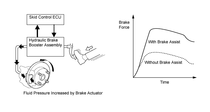
The primary purpose of brake assist is to provide an auxiliary brake force to assist a driver who cannot generate a large brake force during emergency braking, thus helping ensure the vehicle's braking performance.
-
If the brake booster malfunctions and the skid control ECU judges that the brake pedal force applied by the driver is not sufficient to ensure adequate braking force, brake assist is used to enhance the braking force.
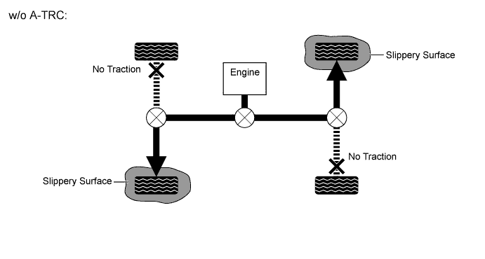
Traction Control (TRC) The TRC helps restrain the slippage of the drive wheels if the driver depresses the accelerator pedal excessively when starting off or while accelerating on a slippery surface. Active Traction Control (A-TRC) A-TRC controls the brake hydraulic pressure that is applied to the slipping wheel, and distributes the drive force that would have been lost through the slippage to the remaining wheels in order to achieve an LSD effect. Vehicle Stability Control (VSC) The VSC helps restrain sideways slippage of the vehicle during a strong front wheel skid or strong rear wheel skid, which may occur while cornering. Trailer Sway Control If the tongue load is not properly adjusted while towing a trailer, trailer sway may be caused due to crosswinds, bumpy roads, steering operation, etc. Trailer sway control detects sway and regulates the brake of each wheel and the engine output in order to suppress trailer sway. Hill-start Assist Control When the vehicle starts off on a steep or a slippery hill, hill-start assist control detects the backward descent of the vehicle and effects 4-wheel hydraulic pressure control to reduce the backward speed of the vehicle. As a result, the vehicle can be started off on a hill more easily. Downhill Assist Control When the downhill assist control switch is pressed while the transfer drive mode is in L4F and L4L, and without accelerator or brake pedal operation, downhill assist control activates to effect 4-wheel hydraulic pressure control, in order to maintain a constant low vehicle speed without causing the wheels to become locked. Thus, the vehicle can descend a steep hill in a stable manner. CRAWL When the vehicle runs on extremely bumpy rough ground or a slippery road, the CRAWL is activated to regulate the engine output and the hydraulic pressure of the 4 wheels, allowing the driver to drive the vehicle at the desired speed and keep that speed with virtually no accelerator or brake pedal operation. As a result, off-road driveability is improved.
-
Anti-lock Brake System (ABS)
-
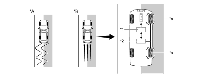
The ABS prevents the wheels from locking during sudden braking or braking on a slippery surface. This provides the proper braking force when the vehicle slips, thus ensuring vehicle stability and excellent braking performance.
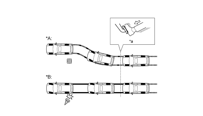
Text in Illustration (Illustration Provides Conceptual Image) *A Models with ABS *B Models without ABS *a Brake Operation - -
-
-
Multi-terrain Anti-lock Brake System (Multi-terrain ABS)
-
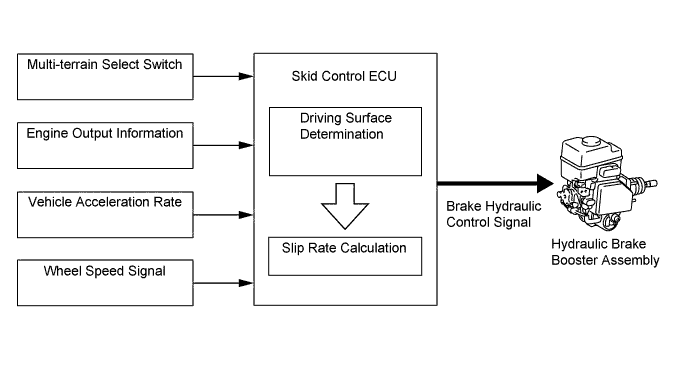
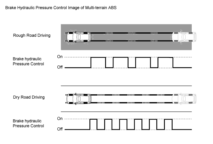
The multi-terrain ABS operates in conjunction with the multi-terrain select. This function detects the off-road driving in sand, mud, gravel, dirt and so on based on signals from the yaw rate sensor assembly, the speed sensor and the ECM, and then automatically switches to the ABS control most appropriate for the road condition.
-
This function is intended to improve the braking feeling when driving off-road without negatively affecting on-road braking control performance.
-
-
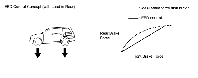
Electronic Brake Force Distribution (EBD)
-
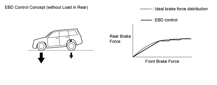
This function controls the brake force that acts on the rear wheels in accordance with the changes in the vehicle conditions such as load factors or deceleration, in order to ensure excellent braking performance.
-
During cornering braking, this function controls the brake force that acts on the left and right wheels in accordance with the vehicle conditions. This ensures vehicle stability and excellent braking performance.

Text in Illustration 
Control Moment 
Brake Force
-
-
Brake Assist
-
During the brake assist, the skid control ECU calculates the speed of the brake pedal application based on the signals from the master cylinder pressure sensor and then determines the intention of the driver to make an emergency brake application. If the skid control ECU determines that the driver intends to make an emergency brake application, this function activates the hydraulic brake booster assembly to increase the brake fluid pressure, which increases the brake force.
-
-
Traction Control (TRC)
-
The TRC helps prevent the drive wheels from slipping if the driver depresses the accelerator pedal excessively when starting off or accelerating on a slippery surface. Simultaneously with the hydraulic brake control of the drive wheels, the skid control ECU makes a request to the ECM to effect engine output control. This produces the drive force that suits the driving conditions, in order to ensure the proper start-off acceleration.
Text in Illustration (Driving on Road with Different Surface Friction Characteristics) *A Models without TRC *B Models with TRC *1 ECM
- Engine Output Control
*2 Brake Actuator Assembly
- Hydraulic Brake Control
*a Brake Slipping Drive Wheel - - 
Slippery Surface - -
-
-
Active Traction Control (A-TRC)
-
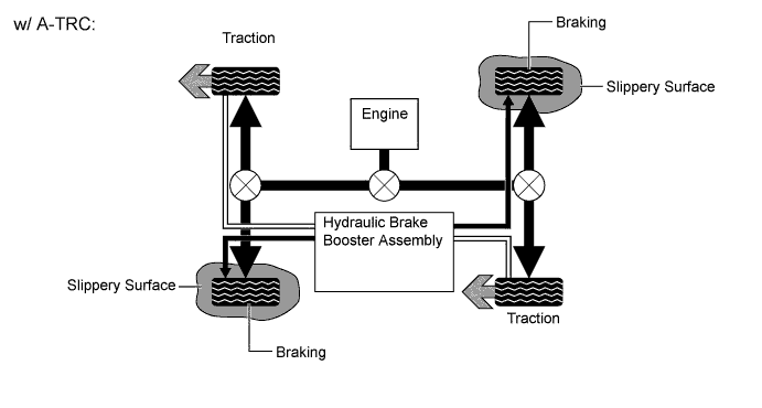
When the vehicle drive mode is L4F* or L4L*, the A-TRAC helps restrain wheelspin by controlling the brake hydraulic pressure that is applied to the spinning wheels, and distributes the drive force that would have been lost through the slippage to the remaining wheels in order to achieve an effect that is similar to Limited Slip Differential (LSD).
Tech Tips
*: When multi-terrain select is on (models with multi-terrain select)
-
The A-TRC independently controls the brake hydraulic pressure to the four wheels in accordance with the extent of the slippage at the wheels, as detected by the skid control ECU.
-
-
Vehicle Stability Control (VSC)
-
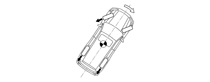
The following are 2 examples that can be considered circumstances in which the tires exceed their lateral grip limit. The VSC is designed to help control the vehicle behavior by controlling the engine output and the brakes of each wheel when the vehicle is under one of the conditions indicated below:
Text in Illustration *a Front Wheel Skid Tendency (Understeer)
- When the front wheels lose grip in relation to the rear wheel
*b Rear Wheel Skid Tendency (Oversteer)
- When the rear wheels lose grip in relation to the front wheels
-
To determine the condition of the vehicle, sensors detect the steering angle, vehicle speed, vehicle yaw rate, and vehicle's lateral acceleration, which are then calculated by the skid control ECU.
-
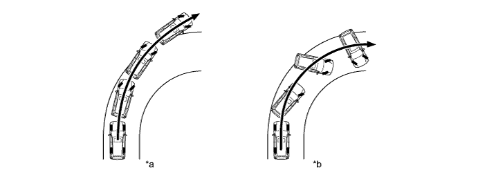
Whether or not the vehicle is experiencing a front wheel skid is determined by the difference between the target yaw rate and the vehicle's actual yaw rate. When the vehicle's actual yaw rate is smaller than the target yaw rate (which is determined based on the vehicle speed and steering angle) that should be generated when the driver operates the steering wheel, it means the vehicle is making a turn at a greater angle than the target locus of travel. Thus, the skid control ECU determines that there is a large front wheel skid tendency.
Text in Illustration *a Actual Locus of Travel (Actual Yaw Rate) *b Locus of Travel Based on Target Yaw Rate -
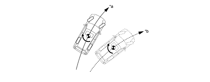
Whether or not the vehicle is experiencing a rear wheel skid is determined by the values of the vehicle's slip angle and the vehicle's slip angular velocity (time-dependent changes in the vehicle's slip angle). When the vehicle's slip angle is large, and the slip angular velocity is also large, the skid control ECU determines that the vehicle has a large rear wheel skid tendency.

Text in Illustration *a Travel Direction of Vehicle's Center of Gravity *b Movement of Vehicle *c Slip Angle - - -
When the skid control ECU determines that the vehicle exhibits a tendency to experience a front wheel skid or a rear wheel skid, it decreases the engine output and applies the brakes of the front or rear wheels to control the vehicle's yaw moment. The basic operation of the VSC is described below. However, the control method differs depending on the vehicle's characteristics and driving conditions.
-
When the skid control ECU determines that there is a large front wheel skid tendency, it takes countermeasures in accordance with the extent of that tendency. The skid control ECU controls the engine output and applies the brakes of the rear wheels and front wheel on the outer circle of the turn in order to help restrain the front wheel skid tendency.
Text in Illustration (Front Wheel Skid Dampening at Right Turn) Control Moment Brake Force -
When the skid control ECU determines that there is a large rear wheel skid tendency, it takes countermeasures in accordance with the extent of that tendency. It applies the brakes of the front and rear wheels of the outer circle of the turn, and generates an outward moment of inertia in the vehicle, in order to restrain the rear wheel skid tendency. Along with the reduction in the vehicle speed caused by the braking force, excellent vehicle stability is ensured. In some cases, the skid control ECU applies the brake of the front wheel on the outer circle of the turn, as necessary.
Text in Illustration (Rear Wheel Skid Dampening at Right Turn) Control Moment Brake Force
-
-
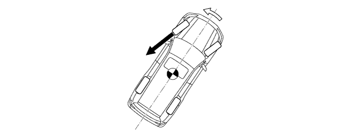
Trailer Sway Control
-
If the vehicle is towing a trailer with an inappropriate hitch load, trailer sway could be caused by crosswinds, imbalance caused by load, or the driver's steering. Trailer sway control reduces trailer sway by controlling the engine output and the braking of each wheel.
Note
-
Trailer sway control is a part of the VSC function. Accordingly, if the VSC OFF mode or VSC is not functioning normally, trailer sway control will not operate.
-
Trailer sway control will be unable to stabilize the vehicle if a trailer is being towed which cannot be physically controlled due to the influence of the vehicle, road surface, driving conditions and so on.
-
-
The skid control ECU detects the occurrence of trailer sway based on signals from the yaw rate sensor assembly and the steering angle sensor.
-
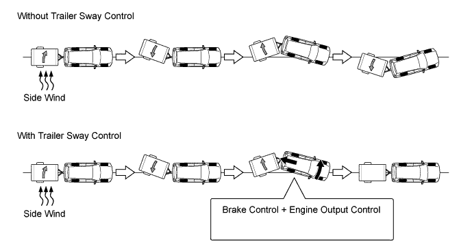
Trailer sway can be reduced by decelerating the vehicle. When the skid control ECU detects trailer sway, it controls the brakes of each wheel while simultaneously requesting engine output control from the ECM and reducing vehicle speed.
-
Moreover, by using brake control to reduce the yaw moment caused by trailer sway, trailer sway can be reduced more quickly than by simply decelerating the vehicle.
-
The slip indicator light on the combination meter assembly flashes when trailer sway control is in operation. Also, the stop light illuminates to inform vehicles behind that the vehicle is decelerating.
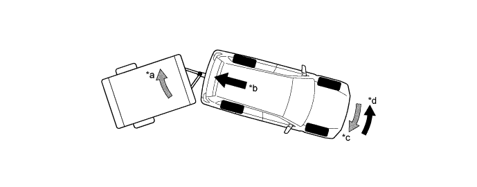
Text in Illustration *a Trailer Sway *b Deceleration Force Caused by Brake Control and Engine Output Control *c Yaw Moment Caused by Trailer Sway *d Control Moment Caused by Brake Control 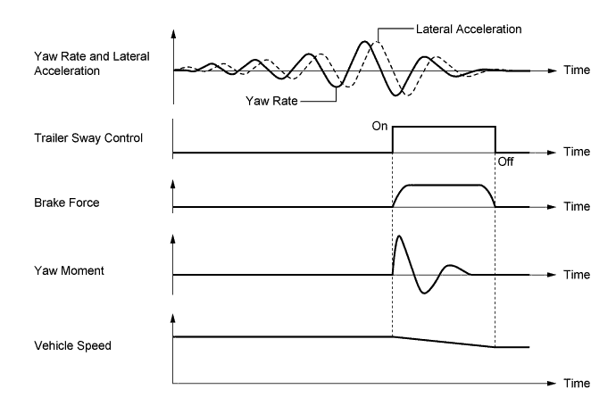
-
-
Hill-start Assist Control
-
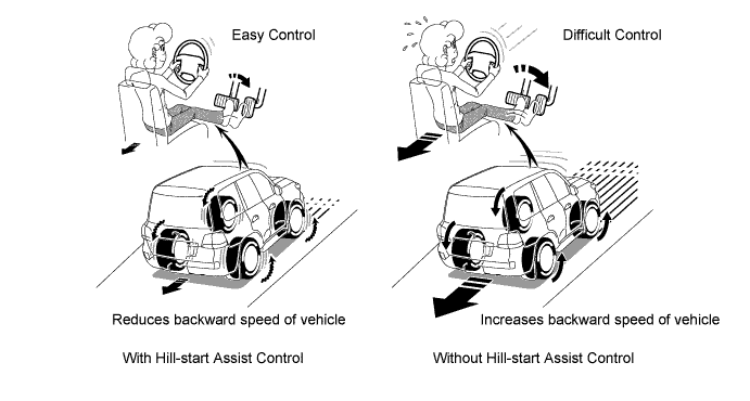
When the vehicle starts off on a steep or slippery hill, the vehicle may start to descend backward while the driver switches from the brake pedal to the accelerator pedal, thus making it difficult for the vehicle to start off. To prevent this from occurring, the hill-start assist control temporarily (approximately 5 seconds at the maximum) applies the brakes to the 4 wheels in order to prevent the vehicle from descending backward.
-
Without the hill-start assist control, the driver must quickly and precisely switch from the brake pedal to the accelerator pedal. With the hill-start assist control, however, the driver can start off easily and operate the pedal in a relaxed manner, because the hill-start assist control prevents the vehicle from descending backward.
-
-
Downhill Assist Control
-
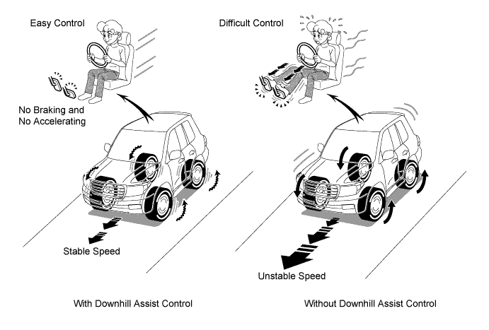
When the vehicle is descending a steep hill and the engine brake alone cannot provide a sufficient deceleration force while the transfer drive mode is in L4F or L4L, downhill assist control effects 4 wheel brake control to maintain a constant, low vehicle speed. Thus, the vehicle is able to descend in a stable manner without causing the wheels to lock.
-
When the vehicle descends a steep hill without downhill assist control, the driver must pay close attention to the brake and accelerator pedal maneuvers. However, with downhill assist control, the driver can concentrate on the steering operation, without accelerator or brake pedal operation.
-
Downhill assist control enables the vehicle to maintain stability because it can descend a slippery hill at low speeds without causing the wheels to lock.
-
-
CRAWL
-
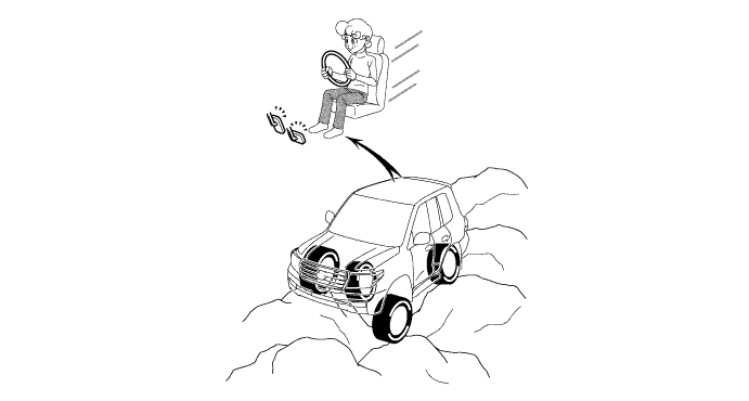
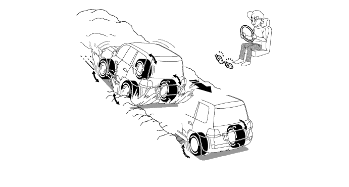
The CRAWL is a driving support system that regulates the engine output and the brake force, enabling the vehicle to be driven at a constant speed on rough ground or slippery roads.
-
When the vehicle drives across rough ground such as extremely bumpy rough roads, the driver needs to pay attention to the steering, braking and acceleration operations. However, with the CRAWL, the driver can concentrate on steering, without worrying about the accelerator pedal or brake pedal.
-
The CRAWL ensures good vehicle stability in situations such as when the vehicle is running on a slippery or steep road because the chances of the wheels spinning or locking are minimized by regulating the engine output and the brake force.
-
-
-
FUNCTION
-
VSC OFF Switch
-
The operation of the VSC and TRC functions can be stopped by the VSC OFF switch. While the vehicle is running off the shoulder of the road or running on a dirt road, the engine output control is stopped to maintain drive torque.
Tech Tips
The VSC OFF switch cannot be operated while multi-terrain select is operating.
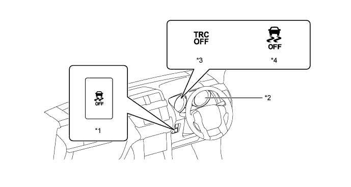
Text in Illustration *1 VSC OFF Switch *2 Combination Meter Assembly *3 TRC OFF Indicator Light *4 VSC OFF Indicator Light -
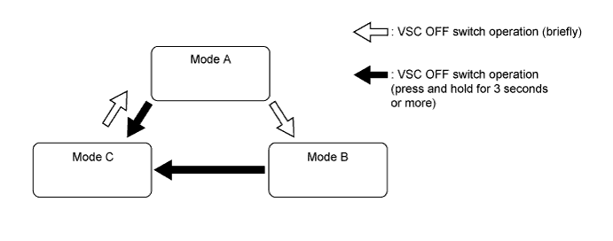
The VSC OFF switch can select 3 modes (mode A, mode B, and mode C).
-
Briefly pressing the VSC OFF switch in mode A selects mode B.
-
Pressing and holding the VSC OFF switch for 3 seconds or more with the vehicle stopped selects mode C.
-
Briefly pressing the VSC OFF switch in mode B or mode C or turning the engine switch off returns to mode A.
-
When TRC is not operating, the TRC OFF indicator light will illuminate.
-
When VSC is not operating, the VSC OFF indicator light will illuminate.
Function of VSC OFF Switch (Models without Multi-terrain Select) Transfer Drive Mode Brake Control Function VSC OFF Switch Mode Mode A Mode B Mode C H4F TRC Operates Does Not Operate Does Not Operate A-TRC Does Not Operate Does Not Operate Does Not Operate VSC Operates Operates Does Not Operate H4L TRC Operates Does Not Operate Does Not Operate A-TRC Does Not Operate Does Not Operate Does Not Operate VSC Operates Operates Does Not Operate L4F TRC Does Not Operate - Does Not Operate A-TRC Operates - Does Not Operate VSC Operates - Does Not Operate L4L TRC Does Not Operate - Does Not Operate A-TRC Operates - Does Not Operate VSC Does Not Operate - Does Not Operate Function of VSC OFF Switch (Models with Multi-terrain Select) Transfer Drive Mode Brake Control Function VSC OFF Switch Mode Mode A Mode B Mode C H4F TRC Operates Does Not Operate Does Not Operate A-TRC Does Not Operate Does Not Operate Does Not Operate VSC Operates Operates Does Not Operate H4L TRC Operates Does Not Operate Does Not Operate A-TRC Does Not Operate Does Not Operate Does Not Operate VSC Operates Operates Does Not Operate L4F TRC Does Not Operate - Does Not Operate A-TRC Does Not Operate - Does Not Operate VSC Operates - Does Not Operate L4L TRC Does Not Operate - Does Not Operate A-TRC Does Not Operate - Does Not Operate VSC Does Not Operate - Does Not Operate
-
-
Multi-terrain Select
-
The multi-terrain select has the following functions:
Multi-terrain Select Function Sends the road mode that is selected by the multi-information switch to the skid control ECU, ECM and 4WD control ECU. Displays a message on the multi-information display prompting the driver to switch to the optimum transfer drive mode if the currently selected road mode and transfer drive mode are inappropriate. Displays an assist message on the multi-information display in order to make switching to the optimum transfer drive mode easier. Automatically switches to the optimum engine output control and switches the brake control function to A-TRC when the selected road mode and transfer drive mode are switched to the optimum position. -
The screen of the multi-information display is switched by operating the multi-terrain select switch and multi-terrain select road mode selector, control is enabled by determining the road mode, and the multi-terrain select indicator light illuminate.
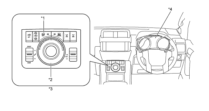
Text in Illustration *1 Multi-terrain Select Switch *2 Multi-terrain Select Road Mode Selector *3 Module Switch *4 Combination Meter Assembly
-
Multi-terrain Select Indicator Light
-
Multi-information Display
-
-
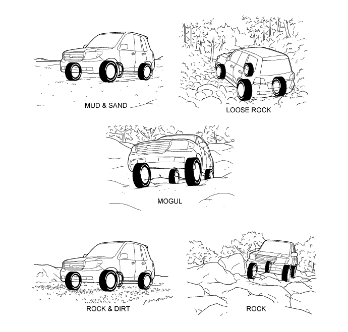
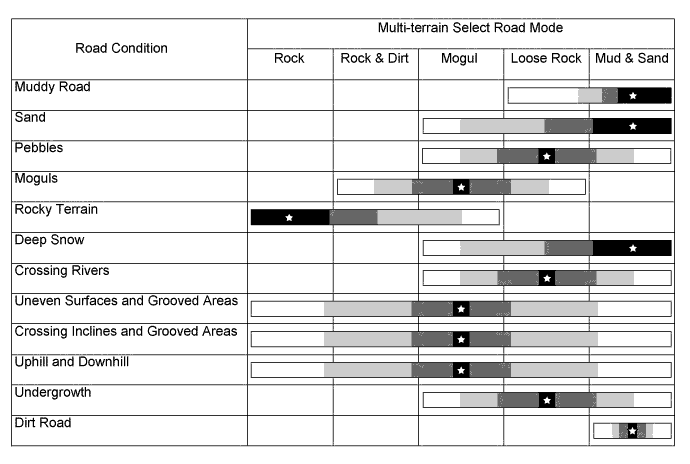
5 road modes can be selected: "MUD & SAND", "LOOSE ROCK", "MOGUL", "ROCK & DIRT" and "ROCK". The recommended road modes for each condition are listed below.
Tech Tips
Road mode recommendations are for reference only. The mode may not be appropriate depending on the road conditions (incline, road surface, road undulation etc.).
-
The engine output and A-TRC control tendency for each road mode are as follows:
Multi-terrain Select Road Mode Transfer Drive Mode Control A-TRC Control Results Mud and Sand L4 The wheels are allowed to slip more than usual. Outputs a large amount of drive force and suppresses deceleration feeling by assuming that the vehicle is driving on a soft, slippery road surface. Loose Rock L4 The wheels are allowed to slip more than usual. Outputs a large amount of drive force and suppresses deceleration feeling by assuming that the vehicle is driving on slippery or loose-graveled uphill slopes. Mogul L4 The wheels are allowed to slip more than usual. Suppresses deceleration feeling to achieve smooth driving on hills while improving LSD function by assuming that the vehicle is driving on a highly bumpy road surface. Rock and Dirt L4 The wheels are made to grip more than usual. Gives the wheels grip and improves the LSD function by assuming that the vehicle is driving on a highly bumpy road surface. Rock L4 The wheels are made to grip more than usual. Gives the wheels grip and improves the LSD function by assuming that the vehicle is driving on a highly bumpy road surface. -
The driver is informed of multi-terrain select operation by the flashing or illumination of the multi-terrain select indicator light and the slip indicator light. Also, operation assist messages are displayed on the multi-information display.
System Condition Indicator Light and Multi-information Display Multi-terrain Select Indicator Light Slip Indicator Light Multi-information Display Message Operates ○ X - A-TRC Operates ○ ▲ - A-TRC Control → A-TRC Control Released ○ → X ▲ → X MULTI-TERRAIN SELECT HAS BEEN CANCELLED Control Commencement Conditions Not Met Transfer Drive Mode Mismatch X X SHIFT TO L4 During CRAWL Control ○ or X ▲ OPERATION NOT POSSIBLE WHEN CRAWL CONTROL ACTIVATED Malfunction Multi-terrain Select ▲ X MULTI-TERRAIN SELECT NOT AVAILABLE Related System Switching Commencement Conditions Not Met ○ X OPERATION NOT POSSIBLE WHEN MULTI-TERRAIN SELECT ACTIVATED Operation Assist ○ or ▲ or X X STOP THE VEHICLE AND SHIFT THE AUTOMATIC TRANSMISSION TO N Tech Tips
○: Illuminates
▲: Blinks
X: Turns off
-
-
-
CONSTRUCTION
-
Yaw Rate Sensor Assembly
-
This sensor has a built-in deceleration sensor.
-
The yaw rate sensor detects the vehicle's yaw rate.
-
The deceleration sensor detects the vehicle's longitudinal and lateral acceleration.
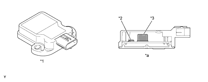
Text in Illustration *1 Yaw Rate Sensor Assembly *2 Deceleration Sensor *3 Yaw Rate Sensor - - *a Cross Section - -
-
-
Steering Angle Sensor
-
The steering angle sensor detects the steering direction and angle, and sends this information to the skid control ECU.
-
-
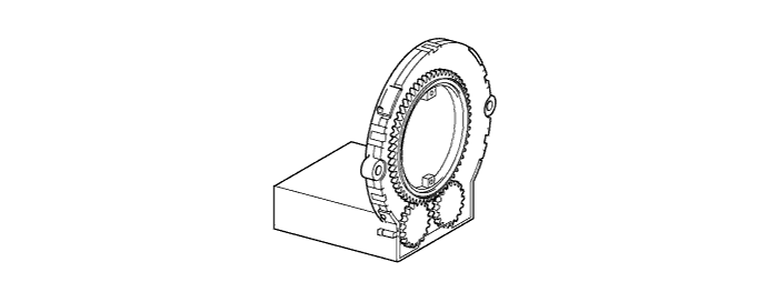
Speed Sensor
-
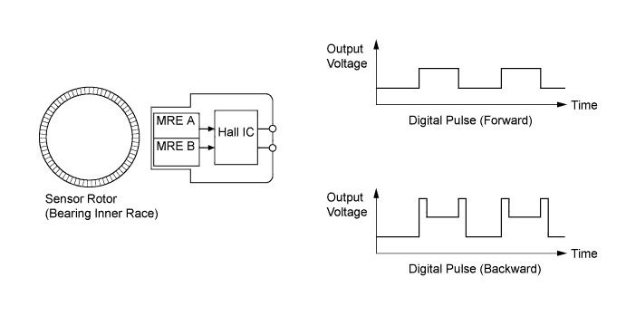
Active type speed sensors, which can detect the rotational direction of the wheel, have been provided. This type of sensor contains a Hall IC, which consists of 2 Magnetic Resistance Elements (MREs).
-
The magnet type rotor, which consists of N and S poles that are arranged in a circle, is integrated with the hub bearing inner race.
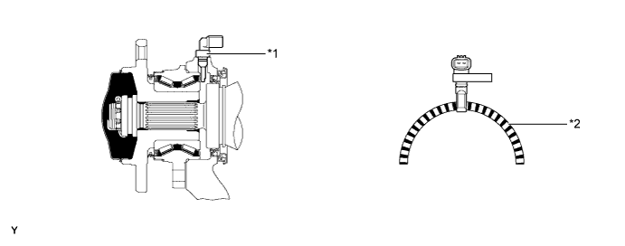
Text in Illustration (Front Axle) *1 Front Speed Sensor *2 Sensor Rotor 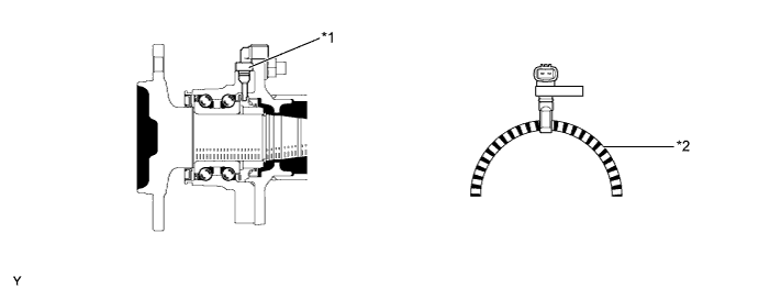
Text in Illustration (Rear Axle) *1 Rear Speed Sensor *2 Sensor Rotor
-
-
Stop Light Switch Assembly
-
A non-contact type stop light switch assembly with high durability is used.
-
The movement of the magnet placed on the shaft is detected by the magnetic sensor.
-
2 magnetic sensors are installed and they output stop light illumination signals and cruise control system cancel signals.
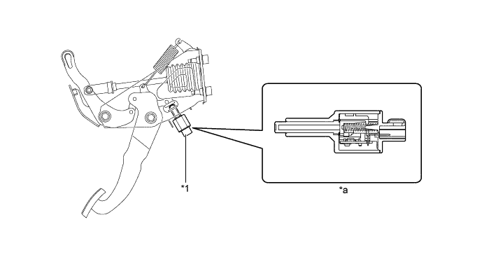
Text in Illustration *1 Stop Light Switch Assembly - - *a Stop Light Switch Assembly Cross Section - -
-
-
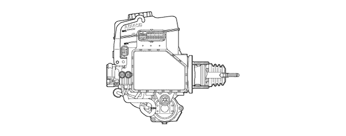
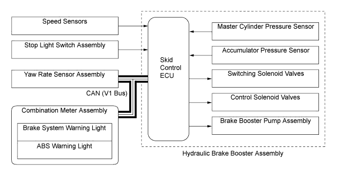
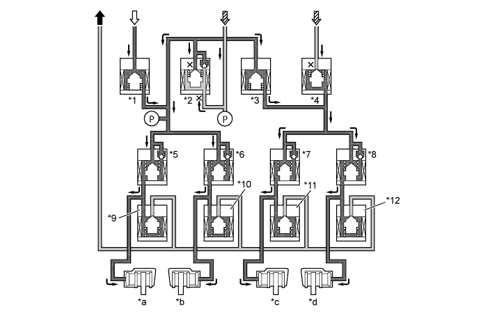
Hydraulic Brake Booster Assembly
-
The brake actuator portion of the hydraulic brake booster consists of 4 switching solenoid valves, 8 control solenoid valves and a skid control ECU.
-
The pressure increase mode, the pressure holding mode, and the pressure reduction mode are effected based on the combination of these solenoid valves, which are turned on and off in order to control the hydraulic pressure that is applied to each of the wheel cylinders.
-
4 switching solenoid valves are used: 2 (SMCF, SREA) in the front brake fluid path, 1 (SREC) in the rear brake fluid path, and 1 (STR) in the accumulator fluid path. The switching solenoid valves open and close in accordance with the control signals from the skid control ECU in order to switch the respective brake fluid path.
-
The 8 control solenoid valves are used for the 4 wheels (2 types per wheel: pressure holding solenoid and pressure reduction solenoid).
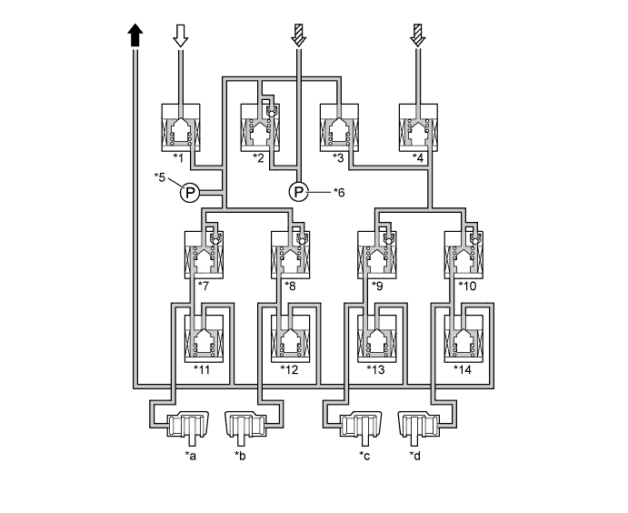
Text in Illustration *1 STR (Traction Solenoid Valve) *2 SREC (Regulator Cut Solenoid Valve) *3 SREA (Regulator Apply for Front Solenoid Valve) *4 SMCF (Master Cut for Front Solenoid Valve) *5 Control Pressure Sensor (Models with Dynamic Radar Cruise Control System) *6 Master Cylinder Pressure Sensor *7 SH (Pressure Holding Solenoid Valve) *8 SH (Pressure Holding Solenoid Valve) *9 SH (Pressure Holding Solenoid Valve) *10 SH (Pressure Holding Solenoid Valve) *11 SR (Pressure Reduction Solenoid Valve) *12 SR (Pressure Reduction Solenoid Valve) *13 SR (Pressure Reduction Solenoid Valve) *14 SR (Pressure Reduction Solenoid Valve) *a Rear LH *b Rear RH *c Front LH *d Front RH To Brake Master Cylinder Reservoir From Brake Booster Accumulator Assembly 
From Brake Master Cylinder - -
-
-
-
OPERATION
-
Speed Sensor
-
The active type speed sensor uses a Hall IC to detect magnetic field changes caused when the sensor rotor rotates, and the sensor outputs the detected information to the skid control ECU as digital pulses.
-
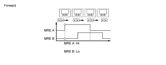
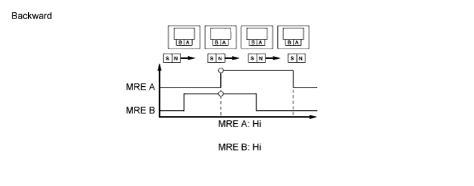
To detect the rotation direction, the output waves are used to determine the relationship of the pulses that are generated by the 2 Magnetic Resistance Elements (MREs).
-
Upon receiving this signal, the Hall IC outputs a forward or backward wave.
-
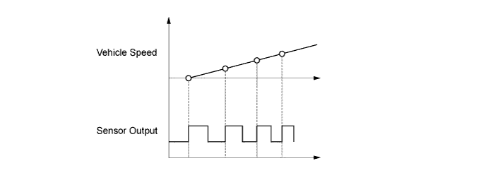
The frequency of the output pulses is used to detect the vehicle speed. Because the active type sensor outputs digital pulses, it can detect vehicle speeds even when the vehicle is nearly stationary.
-
-
ABS and EBD
-
Based on the signals received from the 4 speed sensors, the skid control ECU calculates the speed of each wheel, and checks wheel slipping conditions.
-
The skid control ECU compares the speed sensor signals of the front and rear, judges the slipping condition of the rear wheel, and operates the EBD.
-
When a wheel is about to lock, the ABS operation starts in order to regulate the hydraulic pressure at the wheel cylinders while switching between the 3 modes: pressure increase, pressure holding, and pressure reduction.

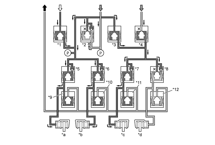
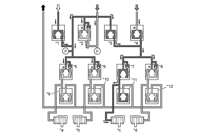
EBD Operation Item EBD Not Activated EBD Activated Increase Mode Holding Mode Reduction Mode Switching Solenoid Valve *1 STR Off (Closed) ← ← ← *2 SREC Off (Open) ← ← ← *3 SREA Off (Closed) ← ← ← *4 SMCF Off (Open) ← ← ← Control Solenoid Valve Front Brake LH *7 SH Off (Open) ← On (Closed) ← *11 SR Off (Closed) ← ← On (Open) *c Wheel Cylinder Pressure - Increases Holds Reduces Front Brake RH *8 SH Off (Open) ← On (Closed) ← *12 SR Off (Closed) ← ← ← *d Wheel Cylinder Pressure - - - - Rear Brake LH *5 SH Off (Open) On (Closed) ← ← *9 SR Off (Closed) ← ← ← *a Wheel Cylinder Pressure - - - - Rear Brake RH *6 SH Off (Open) On (Closed) ← ← *10 SR Off (Closed) ← ← ← *b Wheel Cylinder Pressure - - - - To Brake Master Cylinder Reservoir From Brake Booster Accumulator Assembly From Brake Master Cylinder 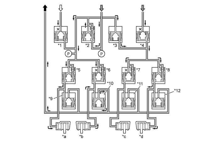
ABS Operation Item ABS Not Activated ABS Activated Increase Mode Holding Mode Reduction Mode Switching Solenoid Valve *1 STR Off (Closed) ← ← ← *2 SREC Off (Open) ← ← ← *3 SREA Off (Closed) On (Open) ← ← *4 SMCF Off (Open) On (Closed) ← ← Control Solenoid Valve Front Brake LH *7 SH Off (Open) ← On (Closed) ← *11 SR Off (Closed) ← ← On (Open) *c Wheel Cylinder Pressure - Increases Holds Reduces Front Brake RH *8 SH Off (Open) ← On (Closed) ← *12 SR Off (Closed) ← ← Off (Open) *d Wheel Cylinder Pressure - Increases Holds Reduces Rear Brake LH *5 SH Off (Open) ← On (Closed) ← *9 SR Off (Closed) ← ← On (Open) *a Wheel Cylinder Pressure - Increases Holds Reduces Rear Brake RH *6 SH Off (Open) ← On (Closed) ← *10 SR Off (Closed) ← ← On (Open) *b Wheel Cylinder Pressure - Increases Holds Reduces To Brake Master Cylinder Reservoir From Brake Booster Accumulator Assembly From Brake Master Cylinder Tech Tips
While the front wheels are in the ABS operation, SREA and SMCF are on. While only rear wheels are in the ABS operation, SREA and SMCF are off.
-
-
Multi-terrain ABS
-
The skid control ECU calculates the speed and deceleration of each wheel, and checks the wheel slipping condition based on signals from the 4 speed sensors and the yaw rate sensor assembly as well as the engine output information transmitted from the ECM.
-
If the wheel is likely to lock, the skid control ECU controls the pressure holding solenoid valve and pressure reduction solenoid valve as multi-terrain ABS operation in the following 3 modes: increase mode, holding mode, and reduction mode.
Multi-terrain ABS Operation Item Multi-terrain ABS Not Activated Multi-terrain ABS Activated Increase Mode Holding Mode Reduction Mode Switching Solenoid Valve *1 STR Off (Closed) ← ← ← *2 SREC Off (Open) ← ← ← *3 SREA Off (Closed) On (Open) ← ← *4 SMCF Off (Open) On (Closed) ← ← Control Solenoid Valve Front Brake LH *7 SH Off (Open) ← On (Closed) ← *11 SR Off (Closed) ← ← On (Open) *c Wheel Cylinder Pressure - Increases Holds Reduces Front Brake RH *8 SH Off (Open) ← On (Closed) ← *12 SR Off (Closed) ← ← On (Open) *d Wheel Cylinder Pressure - Increases Holds Reduces Rear Brake LH *5 SH Off (Open) ← On (Closed) ← *9 SR Off (Closed) ← ← On (Open) *a Wheel Cylinder Pressure - Increases Holds Reduces Rear Brake RH *6 SH Off (Open) ← On (Closed) ← *10 SR Off (Closed) ← ← On (Open) *b Wheel Cylinder Pressure - Increases Holds Reduces To Brake Master Cylinder Reservoir From Brake Booster Accumulator Assembly From Brake Master Cylinder Tech Tips
-
While the front wheels are in the multi-terrain ABS operation, SREA and SMCF are on.
-
While only rear wheels are in the multi-terrain ABS operation, SREA and SMCF are off.
-
-
-
Brake Assist
-
If an emergency braking situation has occurred, it is detected by the skid control ECU based on the vehicle speed signal from the speed sensor, the brake pedal application speed from the master cylinder pressure sensor, and the signal representing the amount of pedal effort. Then, the skid control ECU actuates each solenoid valve. As a result, the pressure from the brake booster accumulator assembly is applied to the wheel cylinders. The accumulator pressure that is applied to the wheel cylinders generates a higher pressure than the master cylinder.
Brake Assist Operation Item Brake Assist Not Activated Brake Assist Activated Increase Mode Holding Mode Reduction Mode Switching Solenoid Valve *1 STR Off (Closed) On (Open) ← Off (Closed) *2 SREC Off (Open) On (Closed) ← Off (Open) *3 SREA Off (Closed) On (Open) ← ← *4 SMCF Off (Open) On (Closed) ← ← Control Solenoid Valve Front Brake LH *7 SH Off (Open) ← On (Closed) ← *11 SR Off (Closed) ← ← On (Open) *c Wheel Cylinder Pressure - Increases Holds Reduces Front Brake RH *8 SH Off (Open) ← On (Closed) ← *12 SR Off (Closed) ← ← On (Open) *d Wheel Cylinder Pressure - Increases Holds Reduces Rear Brake LH *5 SH Off (Open) ← On (Closed) ← *9 SR Off (Closed) ← ← On (Open) *a Wheel Cylinder Pressure - Increases Holds Reduces Rear Brake RH *6 SH Off (Open) ← On (Closed) ← *10 SR Off (Closed) ← ← On (Open) *b Wheel Cylinder Pressure - Increases Holds Reduces To Brake Master Cylinder Reservoir From Brake Booster Accumulator Assembly From Brake Master Cylinder
-
-
TRC
-
The fluid pressure that is generated by the brake booster pump assembly is regulated by the switching solenoid valves and control solenoid valves to the required pressure. Thus, the pressure to the wheel cylinders of the drive wheels is controlled in the following 3 modes: increase mode, holding mode, and reduction mode, to restrain the slippage of the drive wheels.
-
The skid control ECU outputs a TRC operation signal to the ECM. Upon receiving this signal, the ECM effects engine output control.
-
If the accumulator pressure drops during this operation, the skid control ECU receives the signals from the accumulator pressure sensor and actuates the brake booster pump assembly to ensure the proper accumulator pressure.
TRC Operation Item TRC Not Activated TRC Activated Increase Mode Holding Mode Reduction Mode Switching Solenoid Valve *1 STR Off (Closed) On (Open) ← Off (Closed) *2 SREC Off (Open) On (Closed) ← Off (Open) *3 SREA Off (Closed) On (Open) ← ← *4 SMCF Off (Open) On (Closed) ← ← Control Solenoid Valve Front Brake LH *7 SH Off (Open) ← On (Closed) ← *11 SR Off (Closed) ← ← On (Open) *c Wheel Cylinder Pressure - Increases Holds Reduces Front Brake RH *8 SH Off (Open) ← On (Closed) ← *12 SR Off (Closed) ← ← On (Open) *d Wheel Cylinder Pressure - Increases Holds Reduces Rear Brake LH *5 SH Off (Open) ← On (Closed) ← *9 SR Off (Closed) ← ← On (Open) *a Wheel Cylinder Pressure - Increases Holds Reduces Rear Brake RH *6 SH Off (Open) ← On (Closed) ← *10 SR Off (Closed) ← ← On (Open) *b Wheel Cylinder Pressure - Increases Holds Reduces To Brake Master Cylinder Reservoir From Brake Booster Accumulator Assembly From Brake Master Cylinder
-
-
A-TRC
-
Based on the vehicle speed that has been calculated from each speed sensor and the signals of the yaw rate and deceleration sensor, the skid control ECU computes the target control speed.
-
The skid control ECU compares the target control speed and the wheel speed to determine whether or not slippage exists. Upon detecting slippage, the skid control ECU controls the solenoid valve of the hydraulic brake booster assembly to control the brake fluid pressure that is applied to the slipping wheel. When the wheel speed becomes lower than the target control speed, the skid control ECU stops increasing the brake fluid pressure.
-
The fluid pressure control of the A-TRC independently controls the brake of each wheel by operating the individual solenoid valves in accordance with the signals received from the skid control ECU. The brake of each wheel is controlled in the following 3 modes: pressure increase, pressure holding, and pressure reduction modes.
A-TRC Operation Item A-TRC Not Activated A-TRC Activated Increase Mode Holding Mode Reduction Mode Switching Solenoid Valve *1 STR Off (Closed) On (Open) ← Off (Closed) *2 SREC Off (Open) On (Closed) ← Off (Open) *3 SREA Off (Closed) On (Open) ← ← *4 SMCF Off (Open) On (Closed) ← ← Control Solenoid Valve Front Brake LH *7 SH Off (Open) ← On (Closed) ← *11 SR Off (Closed) ← ← On (Open) *c Wheel Cylinder Pressure - Increases Holds Reduces Front Brake RH *8 SH Off (Open) ← On (Closed) ← *12 SR Off (Closed) ← ← On (Open) *d Wheel Cylinder Pressure - Increases Holds Reduces Rear Brake LH *5 SH Off (Open) ← On (Closed) ← *9 SR Off (Closed) ← ← On (Open) *a Wheel Cylinder Pressure - Increases Holds Reduces Rear Brake RH *6 SH Off (Open) ← On (Closed) ← *10 SR Off (Closed) ← ← On (Open) *b Wheel Cylinder Pressure - Increases Holds Reduces To Brake Master Cylinder Reservoir From Brake Booster Accumulator Assembly From Brake Master Cylinder
-
-
VSC
-
Based on the information provided by various sensors, switches, and the ECM, the skid control ECU determines the vehicle's yaw moment. Then, the skid control ECU controls the fluid pressure that is generated by the brake booster pump assembly and applies it by way of the solenoid valves to the brake wheel cylinder of each wheel in the following 3 modes: pressure increase, pressure holding, and pressure reduction modes. As a result, the tendency of the front wheels or the rear wheels to skid is restrained.
-
At this time, the skid control ECU outputs a VSC operation signal to the ECM and the combination meter and causes the buzzer in the combination meter assembly to sound intermittently. Upon receiving this signal, the ECM controls the engine output. The slip indicator light will blink in the combination meter assembly.
-
During front wheel skid restraining control, the brakes of the rear wheels and front wheel of the outer side of the turn are applied. Also, depending on whether the brake is on or off and on the condition of the vehicle, there are circumstances in which the brake might not be applied to the wheels even if those wheels are targeted for braking. The diagram below shows the hydraulic circuit in the pressure increase mode, as it restrains a front wheel skid while the vehicle is making a right turn.
VSC Operation (Turning Right) Item VSC Not Activated VSC Activated Increase Mode Holding Mode Reduction Mode Switching Solenoid Valve *1 STR Off (Closed) On (Open) ← Off (Closed) *2 SREC Off (Open) On (Closed) ← Off (Open) *3 SREA Off (Closed) On (Open) ← ← *4 SMCF Off (Open) On (Closed) ← ← Control Solenoid Valve Front Brake LH *7 SH Off (Open) ← On (Closed) ← *11 SR Off (Closed) ← ← On (Open) *c Wheel Cylinder Pressure - Increases Holds Reduces Front Brake RH *8 SH Off (Open) On (Closed) ← ← *12 SR Off (Closed) ← ← ← *d Wheel Cylinder Pressure - - - - Rear Brake LH *5 SH Off (Open) ← On (Closed) ← *9 SR Off (Closed) ← ← On (Open) *a Wheel Cylinder Pressure - Increases Holds Reduces Rear Brake RH *6 SH Off (Open) ← On (Closed) ← *10 SR Off (Closed) ← ← On (Open) *b Wheel Cylinder Pressure - Increases Holds Reduces To Brake Master Cylinder Reservoir From Brake Booster Accumulator Assembly From Brake Master Cylinder -
During rear wheel skid restraining control, the front wheel brake of the outer side of the turn is applied. Also, depending on whether the brake is on or off and on the condition of the vehicle, there are circumstances in which the brake might be applied to the rear brake of the outer side of the turn. The diagram below shows the hydraulic circuit in the pressure increase mode, as it restrains a rear wheel skid while the vehicle is making a right turn.
VSC Operation (Turning Right) Item VSC Not Activated VSC Activated Increase Mode Holding Mode Reduction Mode Switching Solenoid Valve *1 STR Off (Closed) On (Open) ← Off (Closed) *2 SREC Off (Open) On (Closed) ← Off (Open) *3 SREA Off (Closed) On (Open) ← ← *4 SMCF Off (Open) On (Closed) ← ← Control Solenoid Valve Front Brake LH *7 SH Off (Open) ← On (Closed) ← *11 SR Off (Closed) ← ← On (Open) *c Wheel Cylinder Pressure - Increases Holds Reduces Front Brake RH *8 SH Off (Open) On (Closed) ← ← *12 SR Off (Closed) ← ← ← *d Wheel Cylinder Pressure - - - - Rear Brake LH *5 SH Off (Open) ← On (Closed) ← *9 SR Off (Closed) ← ← On (Open) *a Wheel Cylinder Pressure - - - - Rear Brake RH *6 SH Off (Open) ← ← ← *10 SR Off (Closed) ← ← On (Open) *b Wheel Cylinder Pressure - Increases Holds Reduces To Brake Master Cylinder Reservoir From Brake Booster Accumulator Assembly From Brake Master Cylinder
-
-
Hill-start Assist Control
-
Based on the information provided by various sensors, switches, and the ECM, the skid control ECU computes the backward movement of the vehicle that occurs when the vehicle starts off on a hill. Then, the skid control ECU controls the fluid pressure that is generated by the pump and pump motor and applies it by way of the solenoid valves to the brake wheel cylinder of each wheel in the following 3 modes: pressure increase, pressure holding, and pressure reduction modes.
-
The skid control ECU determines the state of the backward movement of the vehicle while the driver is attempting to drive uphill, based on the speed sensors and the neutral start switch.
-
The skid control ECU determines the gradient of the hill, the acceleration state of the vehicle, the locked state and the rotation direction of each wheel through the speed sensors and the yaw rate sensor assembly. Then, the skid ECU computes the amount of brake control that will prevent the wheels from locking.
-
During this operation, the skid control ECU outputs a hill-start assist control operation signal to the combination meter. This causes the slip indicator light to blink, sends signals to the stop light control relay which turns on the stop light.
-
The hill-start assist control operates for approximately five seconds. At this time, the skid control ECU informs the driver by the slow and intermittent sound of the buzzer in the combination meter assembly. After this, the skid control ECU alerts the driver by using the quick and intermittent sound of the buzzer in the combination meter assembly, and gradually releases the brake hydraulic pressure in order to end the hill-start assist control operation.
Hill-start Assist Control Operation Item Hill-start Assist Control Not Activated Hill-start Assist Control Activated Increase Mode Holding Mode Reduction Mode Switching Solenoid Valve *1 STR Off (Closed) On (Open) ← Off (Closed) *2 SREC Off (Open) On (Closed) ← Off (Open) *3 SREA Off (Closed) On (Open) ← ← *4 SMCF Off (Open) On (Closed) ← ← Control Solenoid Valve Front Brake LH *7 SH Off (Open) ← On (Closed) ← *11 SR Off (Closed) ← ← On (Open) *c Wheel Cylinder Pressure - Increases Holds Reduces Front Brake RH *8 SH Off (Open) ← On (Closed) ← *12 SR Off (Closed) ← ← On (Open) *d Wheel Cylinder Pressure - Increases Holds Reduces Rear Brake LH *5 SH Off (Open) ← On (Closed) ← *9 SR Off (Closed) ← ← On (Open) *a Wheel Cylinder Pressure - Increases Holds Reduces Rear Brake RH *6 SH Off (Open) ← On (Closed) ← *10 SR Off (Closed) ← ← On (Open) *b Wheel Cylinder Pressure - Increases Holds Reduces To Brake Master Cylinder Reservoir From Brake Booster Accumulator Assembly From Brake Master Cylinder
-
-
Downhill Assist Control
-
Based on the information provided by various sensors, switches, and the engine ECU, the skid control ECU determines the conditions that enable downhill assist control operation. Then, the skid control ECU controls the fluid pressure that is generated by the brake booster pump assembly and applies it by way of the solenoid valve to the brake wheel cylinder of each wheel in the following 3 modes: pressure increase, pressure holding and pressure reduction modes.
-
The skid control ECU computes the vehicle speed, travel direction, and the gradient of the hill in accordance with the signals that are input by the speed sensor and the yaw rate sensor assembly, and effects brake control to attain the target vehicle speed. The target vehicle speed is determined by the direction of the vehicle.
Downhill Assist Control Target Vehicle Speed Travel Direction Forward 5 km/h to 7 km/h (3 mph to 4 mph) Backward 3 km/h to 5 km/h (2 mph to 3 mph) -
During the downhill assist control operation, the skid control ECU outputs signals to the stop light control relay to cause the stop light to turn on, and to the combination meter to cause the slip indicator light to blink.
Downhill Assist Control Operation Item Downhill Assist Control Not Activated Downhill Assist Control Activated Increase Mode Holding Mode Reduction Mode Switching Solenoid Valve *1 STR Off (Closed) On (Open) ← Off (Closed) *2 SREC Off (Open) On (Closed) ← Off (Open) *3 SREA Off (Closed) On (Open) ← ← *4 SMCF Off (Open) On (Closed) ← ← Control Solenoid Valve Front Brake LH *7 SH Off (Open) ← On (Closed) ← *11 SR Off (Closed) ← ← On (Open) *c Wheel Cylinder Pressure - Increases Holds Reduces Front Brake RH *8 SH Off (Open) ← On (Closed) ← *12 SR Off (Closed) ← ← On (Open) *d Wheel Cylinder Pressure - Increases Holds Reduces Rear Brake LH *5 SH Off (Open) ← On (Closed) ← *9 SR Off (Closed) ← ← On (Open) *a Wheel Cylinder Pressure - Increases Holds Reduces Rear Brake RH *6 SH Off (Open) ← On (Closed) ← *10 SR Off (Closed) ← ← On (Open) *b Wheel Cylinder Pressure - Increases Holds Reduces To Brake Master Cylinder Reservoir From Brake Booster Accumulator Assembly From Brake Master Cylinder
-
-
CRAWL
-
Based on the information provided by various sensors, switches, and the ECM, the skid control ECU determines the conditions that enable the CRAWL to operate. The skid control ECU computes the target vehicle speed (approximately 1 km/h to 6 km/h, 1 mph to 3.7 mph) to control the vehicle speed, and the target wheel speeds to control the wheel slipping. The target vehicle speed can be changed using the CRAWL speed selector.
-
When the vehicle speed differs from the target speed, the engine output is regulated. When the wheel speeds differ from the target speeds, the hydraulic brake pressure of the wheels is regulated.
-
The skid control ECU controls the fluid pressure that is generated by the brake booster pump assembly and applies it by way of the solenoid valves to the brake wheel cylinder of each wheel in the following 3 modes: pressure increase, pressure holding, and pressure reduction modes.
CRAWL Operation Item CRAWL Not Activated CRAWL Activated Increase Mode Holding Mode Reduction Mode Switching Solenoid Valve *1 STR Off (Closed) On (Open) ← Off (Closed) *2 SREC Off (Open) On (Closed) ← Off (Open) *3 SREA Off (Closed) On (Open) ← ← *4 SMCF Off (Open) On (Closed) ← ← Control Solenoid Valve Front Brake LH *7 SH Off (Open) ← On (Closed) ← *11 SR Off (Closed) ← ← On (Open) *c Wheel Cylinder Pressure - Increases Holds Reduces Front Brake RH *8 SH Off (Open) ← On (Closed) ← *12 SR Off (Closed) ← ← On (Open) *d Wheel Cylinder Pressure - Increases Holds Reduces Rear Brake LH *5 SH Off (Open) ← On (Closed) ← *9 SR Off (Closed) ← ← On (Open) *a Wheel Cylinder Pressure - Increases Holds Reduces Rear Brake RH *6 SH Off (Open) ← On (Closed) ← *10 SR Off (Closed) ← ← On (Open) *b Wheel Cylinder Pressure - Increases Holds Reduces To Brake Master Cylinder Reservoir From Brake Booster Accumulator Assembly From Brake Master Cylinder
-
-
-
FAIL-SAFE
-
If a failure occurs in the skid control ECU, sensors, or hydraulic brake booster assembly, the system continues effecting brake control by excluding the failed area and using only the areas that are operating normally.
-
-
DIAGNOSIS
-
If the skid control ECU detects a malfunction in the brake control system, the warning or indicator lights illuminate. At the same time, a Diagnostic Trouble Code (DTC) is stored in the memory of the skid control ECU.
-
This system has a sensor signal check (test mode) function.
-
For details of DTC and check function, refer to the Repair Manual.
-