FOUR WHEEL DRIVE CONTROL SYSTEM DETAILS
-
FUNCTION OF MAIN COMPONENTS
Component Function Transfer Shift Actuator Assembly H-L Shift Motor Switches the transfer gear ratio between high and low in accordance with signals from the 4WD control ECU. H-L Limit Switch Detects the position of the H-L shift motor and transmits a signal to the 4WD control ECU. Center Differential Lock Shift Motor Switches the center differential between free and lock in accordance with signals from the 4WD control ECU. Center Differential Lock Limit Switch Detects the position of the center differential lock shift motor and transmits a signal to the 4WD control ECU. Center Differential Lock Position Switch Detects the lock position of the center differential and transmits a signal to the 4WD control ECU and so on. Transfer Position Switch Switches the drive mode and transmits a signal to the 4WD control ECU. Center Differential Lock Switch*1 Switches the center differential between free and lock and transmits a signal to the 4WD control ECU. Clutch Start Switch Assembly*2 Detects that the clutch pedal is completely depressed and transmits a signal to the 4WD control ECU. 4WD Control ECU Controls each shift motor in response to a signal from each switch. ECM
-
Transmits a shift position signal to the 4WD control ECU via CAN.*3
-
Detects the center differential lock position switch signal.*4
TCM*5 Transmits a shift position signal to the ECM via CAN. Combination Meter Assembly 4LO Indicator Light
-
Blinks while switching the transfer gear ratio between high and low, and turns on when in low.
-
Blinks when the switching conditions are not met while switching the transfer gear ratio between high and low.
Center Differential Lock Indicator Light
-
Blinks while switching the center differential between free and lock, and turns on when in lock.
-
Blinks when the switching conditions are not met while switching the center differential between free and lock.
VSC OFF Indicator Light*6 Turns on in accordance with the drive mode when VSC function is not operating. Multi-information Display*7 Displays the status of the center differential lock operation. Multi Buzzer Sounds when the switching conditions are not met while switching the drive mode.
-
*1: Models with 1GR-FE or 1KD-FTV engine
-
*2: Models with manual transmission
-
*3: Models with automatic transmission
-
*4: Models with 2TR-FE engine
-
*5: Models with 1KD-FTV engine and automatic transmission
-
*6: Models with VSC
-
*7: Models with Optitron display type combination meter assembly
-
-
OPERATING CONDITION
-
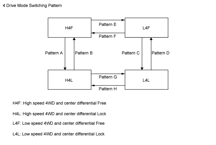
4 Drive Mode (Models with 1GR-FE or 1KD-FTV Engine)
-
The drive mode switching pattern of the 4WD system is as shown in the illustration below:
-
The center differential can be switched between free and lock (switching patterns A to D) when the vehicle is running. However, the center differential should not be switched from free to lock when the vehicle is turning or the tires are spinning.
-
On the models with manual transmission, the transfer gear ratio can be switched between high and low (switching patterns E to H) only when the vehicle is stationary and the clutch pedal is being depressed.
-
On the models with automatic transmission, the transfer gear ratio can be switched between high and low (switching patterns E to H) only when the vehicle is stationary and the shift lever is in N.
-
TRC or VSC function in the brake control system may be stopped, depending on the drive mode. For details, see the Brake Control/Dynamic Control Systems section.
-
-
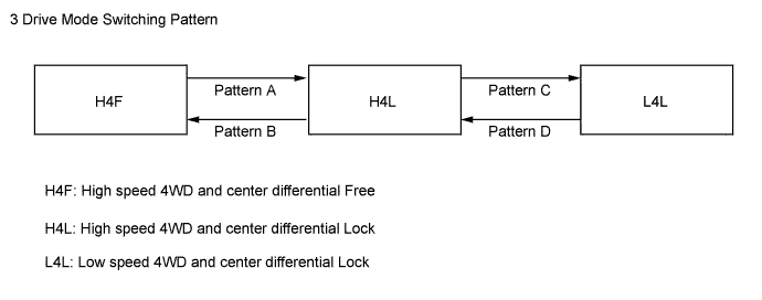
3 Drive Mode (Models with 2TR-FE or 5L-E Engine)
-
The drive mode switching pattern of the 4WD system is as shown in the illustration below:
-
The center differential can be switched between free and lock (switching patterns A and B) when the vehicle is running. However, the center differential should not be switched from free to lock when the vehicle is turning or the tires are spinning.
-
On the models with manual transmission, the transfer gear ratio can be switched between high and low (switching patterns C and D) only when the vehicle is stationary and the clutch pedal is being depressed.
-
On the models with automatic transmission, the transfer gear ratio can be switched between high and low (switching patterns C and D) only when the vehicle is stationary and the shift lever is in N.
-
-
-
CONSTRUCTION
-
Transfer Assembly
-
A planetary gear unit is used in the reduction mechanism.
-
The center differential uses a TORSEN* LSD. As a result, this LSD ensures the proper torque distribution during acceleration and high-speed driving.
Tech Tips
*: TORSEN is a registered trademark of JTEKT Corporation.
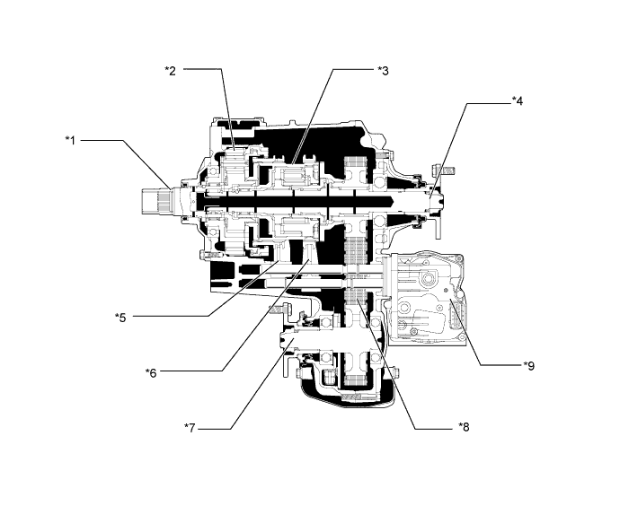
Text in Illustration *1 Transfer Input Shaft *2 Transfer Low Planetary Gear Assembly *3 Center Differential *4 Transfer Rear Output Shaft *5 No. 2 Transfer Gear Shift Fork *6 Center Differential Lock Fork Sub-assembly *7 Transfer Front Output Shaft *8 Transfer Front Drive Chain *9 Transfer Shift Actuator Assembly - -
-
-
Transfer Low Planetary Gear Assembly
-
A transfer low planetary gear assembly is used on the planetary gear unit to switch the transfer gear ratio between high and low.
-
The transfer low planetary gear assembly consists of the planetary sun gear, 4 planetary pinion gears, planetary ring gear, and planetary carrier.
-
The planetary sun gear is integrated with the transfer input shaft. A transfer clutch hub spline piece is fitted to the rear of the planetary sun gear.
-
4 planetary pinion gears are fitted to the planetary carrier. Each pinion gear shaft is fixed to the planetary carrier. A transfer low planetary spline piece is fitted to the rear of the planetary carrier.
-
The planetary ring gear is fixed to the front transfer case and its internal teeth mesh with the planetary pinion gears.
-
In this planetary gear unit, the power transmission route is switched in accordance with the movement of the transfer high and low clutch sleeve. The input power from the transfer input shaft is transmitted to the center differential case via the transfer high and low clutch sleeve.
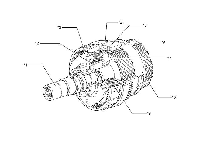
Text in Illustration *1 Transfer Input Shaft *2 Planetary Sun Gear *3 Planetary Ring Gear *4 Planetary Carrier *5 Transfer Low Planetary Spline Piece *6 Transfer High and Low Clutch Sleeve *7 Transfer Clutch Hub Spline Piece *8 Center Differential Case *9 Planetary Pinion Gear - -
-
-
Center Differential
-
The center differential uses a TORSEN* LSD. Also, a mechanism is used to switch the center differential between free and lock.
-
The TORSEN* LSD is a torque-sensing LSD. It generates a limited-differential torque in proportion to the drive torque, and instantly changes the front and rear torque distribution.
Tech Tips
*: TORSEN is a registered trademark of JTEKT Corporation.
-
The torque distribution during straightline driving is 40/60 (front/rear), which is helpful for an appropriate steering response during the initial stage of a turn. During the acceleration stage of a turn, the torque distribution increases in the rear wheels.
-
This center differential consists of a center differential case, sun gear, ring gear, coupling, 8 pinion gears, clutch plates, and planetary carrier.
-
The drive torque is input to the center differential case.
-
The center differential case is connected with the planetary carrier.
-
The sun gear is connected to the front driver sprocket (in the front wheel output side) through the transfer clutch hub and transfer front drive spline piece.
-
The ring gear is connected to the transfer rear output shaft (in the rear wheel output side) through the coupling.
-
The center differential is switched between free and lock in accordance with the movement of the front drive clutch sleeve.
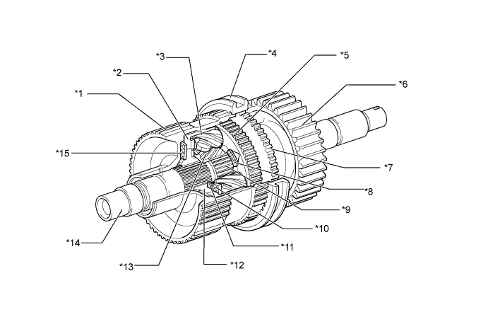
Text in Illustration *1 Center Differential Case *2 Ring Gear *3 Pinion Gear *4 Front Drive Clutch Sleeve *5 Planetary Carrier *6 Front Drive Sprocket *7 Transfer Front Drive Spline Piece *8 No. 4 Clutch Plate *9 Transfer Clutch Hub *10 No. 3 Clutch Plate *11 No. 2 Clutch Plate *12 Coupling *13 Sun Gear *14 Transfer Rear Output Shaft *15 No. 1 Clutch Plate - -
-
-
Transfer Shift Actuator Assembly
-
The transfer shift actuator assembly consists of the high-low switching mechanism (to switch the transfer gear ratio) and the free-lock switching mechanism (to switch the center differential lock).
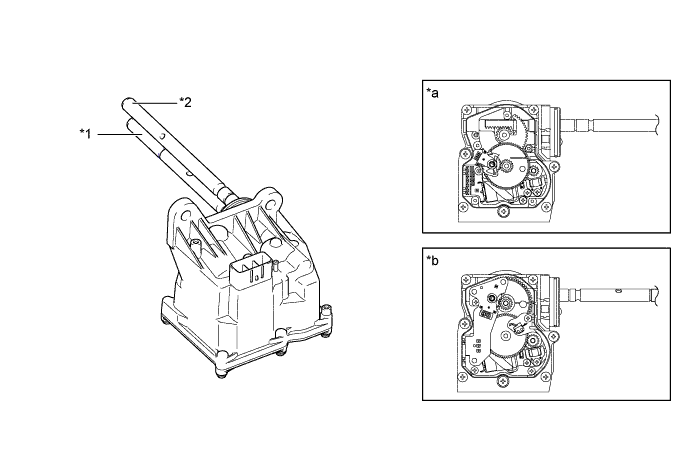
Text in Illustration *1 Center Differential Lock Shift Fork Shaft *2 H-L Shift Fork Shaft *a High-low Switching Mechanism (to Switch Transfer Gear Ratio) *b Free-lock Switching Mechanism (to Switch Center Differential Lock) 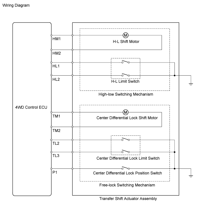
-
High-low Switching Mechanism
-
By rotating the H-L shift motor clockwise or counterclockwise in accordance with a signal from the 4WD control ECU, the H-L shift fork shaft is transferred to switch the transfer gear ratio between high and low.
-
The drive mechanism for switching the transfer gear ratio between high and low consists of an H-L shift motor, H-L limit switch, and H-L shift fork shaft.
-
The H-L limit switch detects the H-L shift motor position.
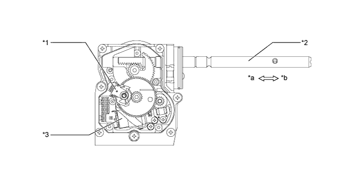
Text in Illustration *1 H-L Limit Switch *2 H-L Shift Fork Shaft *3 H-L Shift Motor - - *a Low Side *b High Side 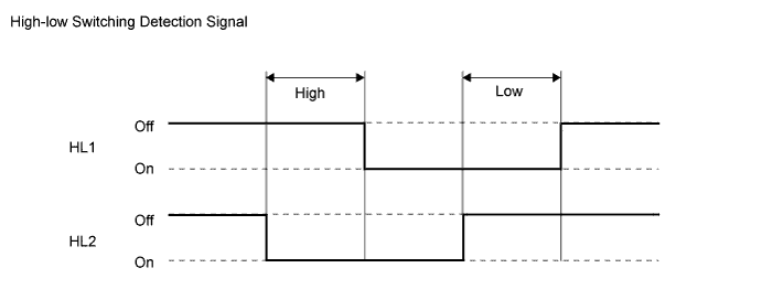
-
Free-lock Switching Mechanism
-
By rotating the center differential lock shift motor clockwise or counterclockwise in accordance with a signal from the 4WD control ECU, the center differential lock shift fork shaft is transferred to switch the center differential between free and lock.
-
The drive mechanism for switching the center differential between free and lock consists of a center differential lock shift motor, center differential lock limit switch, center differential lock position switch, and center differential lock shift fork shaft.
-
The center differential lock limit switch detects the center differential lock shift motor position.
-
The center differential lock position switch detects the lock position of the center differential.
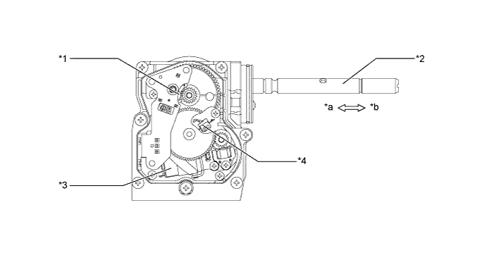
Text in Illustration *1 Center Differential Lock Limit Switch *2 Center Differential Lock Shift Fork Shaft *3 Center Differential Lock Shift Motor *4 Center Differential Lock Position Switch *a Lock Side *b Free Side 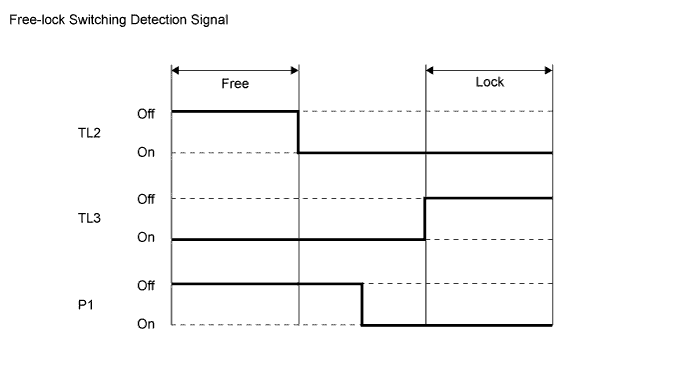
-
-
-
Transfer Position Switch
-
On the models with 1GR-FE or 1KD-FTV engine, operating the transfer position switch can switch the transfer gear ratio between high and low.
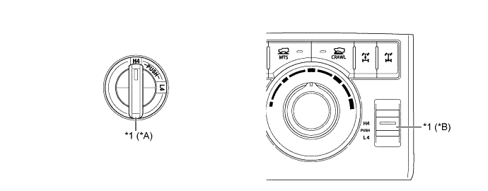
Text in Illustration *A Models without Multi-terrain Select *B Models with Multi-terrain Select *1 Transfer Position Switch - - -
On the models with 2TR-FE or 5L-E engine, operating the rotary type transfer position switch can switch the transfer gear ratio between high and low and the center differential between free and lock.

Text in Illustration *1 Transfer Position Switch - -
-
-
Center Differential Lock Switch (4 Drive Mode)
-
On the models with 1GR-FE or 1KD-FTV engine, operating the push type center differential lock switch can switch the center differential between free and lock.
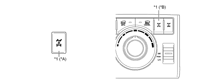
Text in Illustration *A Models without Multi-terrain Select *B Models with Multi-terrain Select *1 Center Differential Lock Switch - -
-
-
-
OPERATION
-
High-low Switching of Transfer Gear Ratio
-
High Position
-
In the high position, the internal gear teeth of the transfer high and low clutch sleeve mesh with the transfer clutch hub spline piece.
-
Also, the transfer high and low clutch sleeve is connected to the center differential case.
-
The rotation of the transfer input shaft is transmitted to the planetary sun gear, transfer clutch hub spline piece, transfer high and low clutch sleeve, and the differential case.
Text in Illustration *1 Planetary Sun Gear *2 Planetary Pinion Gear *3 Planetary Ring Gear *4 Planetary Carrier *5 Transfer High and Low Clutch Sleeve *6 Transfer Input Shaft *7 Transfer Clutch Hub Spline Piece *8 Center Differential Case -
-
Low Position
-
In the low position, the external teeth of the transfer high and low clutch sleeve mesh with the transfer low planetary spline piece.
-
Also, the transfer high and low clutch sleeve is connected to the center differential case.
-
The rotation of the transfer input shaft is transmitted in a reduced form to the planetary sun gear, planetary pinion gears, planetary pinion gear shafts, planetary carrier, transfer low planetary spline piece, transfer high and low clutch sleeve, and center differential case.
Text in Illustration *1 Planetary Sun Gear *2 Planetary Pinion Gear *3 Planetary Ring Gear *4 Planetary Carrier *5 Transfer Low Planetary Spline Piece *6 Transfer High and Low Clutch Sleeve *7 Transfer Input Shaft *8 Center Differential Case -
-
-
Free-lock Switching of Center Differential
-
Lock Position
-
In the lock position, the front drive clutch sleeve connects the center differential case and the transfer front drive spline piece to set the center differential to lock.
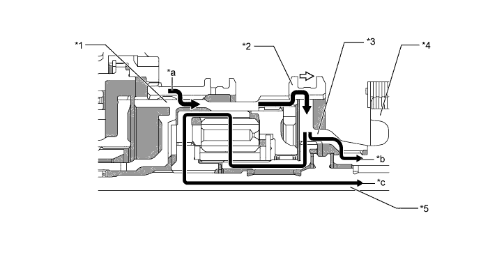
Text in Illustration *1 Center Differential Case *2 Front Drive Clutch Sleeve *3 Transfer Front Drive Spline Piece *4 Front Drive Sprocket *5 Transfer Rear Output Shaft - - *a Input Torque *b Front Output Torque *c Rear Output Torque - - -
-
-
Operation of Center Differential
-
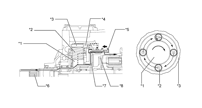
Normal Driving Operation
-
During normal driving (front wheel speed = rear wheel speed), the drive torque that is input by the differential case is transmitted (front: 40/rear: 60) as shown below, without involving the LSD function.
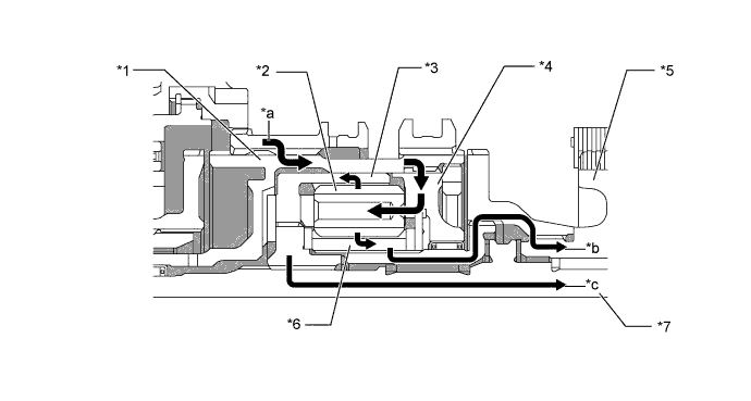
Text in Illustration *1 Center Differential Case *2 Pinion Gear *3 Ring Gear *4 Planetary Carrier *5 Front Drive Sprocket *6 Sun Gear *7 Transfer Rear Output Shaft - - *a Input Torque *b Front Output Torque *c Rear Output Torque - - -
-
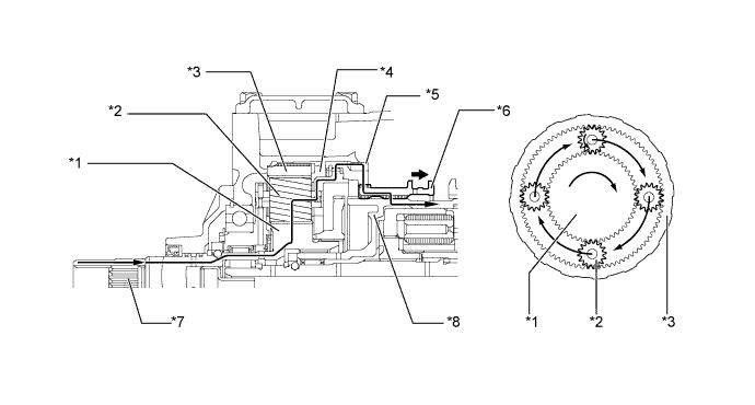
Front Wheel Skid Driving Operation
-
During front wheel skid driving (front wheel speed > rear wheel speed) when a rotational difference exists between the sun gear and the ring gear, the distribution of the drive torque that is input by the center differential case changes instantly before the torque is transmitted, as follows:
-
The sun gear transmits torque to the planetary carrier while pushing on the No. 4 clutch plate. The planetary carrier transmits this torque to the ring gear from the center differential case via the No. 1 clutch plate.
-
The ring gear outputs torque while pushing on the No. 1 clutch plate.
-
These LSD functions change the torque distribution.
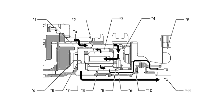
Text in Illustration *1 Center Differential Case *2 Pinion Gear *3 Ring Gear *4 Planetary Carrier *5 Front Drive Sprocket *6 No. 1 Clutch Plate *7 Coupling *8 Sun Gear *9 No. 4 Clutch Plate *10 Transfer Clutch Hub *11 Transfer Rear Output Shaft - - *a Input Torque *b Front Output Torque *c Rear Output Torque *d Pushing on No. 1 Clutch Plate *e Pushing on No. 4 Clutch Plate - - -
-
Rear Wheel Skid Driving Operation
-
During rear wheel skid driving (front wheel speed < rear wheel speed), when a rotational difference exists between the sun gear and the ring gear, the distribution of the drive torque that is input by the center differential case changes instantly before the torque is transmitted, as follows:
-
The ring gear transmits torque to the center differential case while pushing on the No. 1 clutch plate. The center differential case transmits this torque from the planetary carrier to the sun gear via the No. 4 clutch plate.
-
The sun gear outputs torque while pushing on the No. 4 clutch plate.
-
These LSD functions change the torque distribution.
-
-
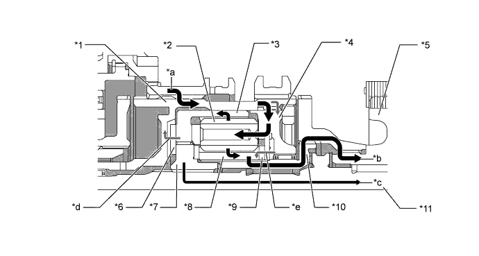
Text in Illustration *1 Center Differential Case *2 Pinion Gear *3 Ring Gear *4 Planetary Carrier *5 Front Drive Sprocket *6 No. 1 Clutch Plate *7 Coupling *8 Sun Gear *9 No. 4 Clutch Plate *10 Transfer Clutch Hub *11 Transfer Rear Output Shaft - - *a Input Torque *b Front Output Torque *c Rear Output Torque *d Pushing on No. 1 Clutch Plate *e Pushing on No. 4 Clutch Plate - - -