AUTOMATIC TRANSMISSION SYSTEM DETAILS
-
FUNCTION OF MAIN COMPONENTS
Component Function ATF Warmer*1 Warms up the ATF quickly. Air-cooled Type ATF Cooler*2 Cools down the ATF. Torque Converter Clutch Assembly
-
Transmits the engine power to the transmission.
-
Increases engine torque.
Oil Pump Provides oil pressure necessary for the transmission operation. No. 1 Clutch (C1)
Connects the input shaft and the intermediate shaft. No. 2 Clutch (C2)
Connects the input shaft and the center planetary carrier. No. 3 Clutch (C3)
Connects the input shaft and the front sun gear. No. 1 Brake (B1)
Prevents the front planetary carrier from turning either clockwise or counterclockwise. No. 2 Brake (B2)
Prevents the front and center planetary ring gears from turning either clockwise or counterclockwise. No. 3 Brake (B3)
Prevents the outer race of F2from turning either clockwise or counterclockwise.
No. 4 Brake (B4)
Prevents the center planetary carrier and the rear planetary ring gear from turning either clockwise or counterclockwise. No. 1 1-way Clutch (F1)
Prevents the front planetary carrier from turning counterclockwise. No. 2 1-way Clutch (F2)
Prevents the front planetary sun gear from turning counterclockwise when B3is operating.
No. 3 1-way Clutch (F3)
Prevents the center planetary carrier and the rear planetary ring gear from turning counterclockwise. Planetary Gears These gears change the route through which driving force is transmitted, in accordance with the operation of each clutch and brake, in order to increase or reduce the input and output speed. Shift Solenoid Valve DSL (S1) Switches the 2-3 shift valve. No. 3 transmission Solenoid Assembly (S2) Switches the 1-2 shift valve or 3-4 shift valve. Shift Solenoid Valve S4 (SR) Switches the clutch apply control valve. Shift Solenoid Valve (SL1)
-
Controls clutch pressure.
-
Controls accumulator back pressure.
Shift Solenoid Valve (SL2) Controls brake pressure. Line Pressure Control Solenoid Assembly (SLT)
-
Controls line pressure.
-
Controls accumulator back pressure.
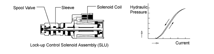
Lock-up Control Solenoid Assembly (SLU)
-
Controls lock-up clutch pressure.
-
Controls accumulator back pressure.
ATF Temperature Sensors Detects the ATF temperature. Transmission Revolution Sensor (NT) Detects the input speed of the transmission. Transmission Revolution Sensor (SP2) Detects the output speed of the transmission. Park/Neutral Position Switch Assembly Detects the shift lever position (P, R, N, D). Transmission Control Switch
-
Detects that the shift lever is in S.
-
Detects the driver's shift-up and shift-down operations when the shift lever is in S.
2nd Start Switch (Pattern Select Switch Assembly)*3 Switches the 2nd start mode. ECM
-
Controls each shift solenoid valve and engine output in response to a signal from each sensor and switch.*4
-
Controls engine output in response to a signal from the TCM.*5
-
When the ECM detects a malfunction, it makes a diagnosis and memorizes the failed section.
TCM*5
-
Controls each shift solenoid valve in response to a signal from each sensor and switch.
-
When the TCM detects a malfunction, it makes a diagnosis and memorizes the failed section.
4WD Control ECU Sends a drive mode signal to the ECM or TCM. Air Conditioning Amplifier Assembly Sends a shift-up tardiness control signal to the ECM. Driving Support ECU Assembly*6 Sends a shifting control request signal to the ECM. Driving Support Switch Control ECU*7
-
Sends a 2nd start mode signal to the ECM.
-
Sends a multi-terrain select control signal to the ECM.*8
Combination Meter Assembly Shift Display
-
Indicates the shift lever position.
-
Indicates to inform the driver of driving in D mode or S mode.
-
Indicates the shift range (S1 to S5).
MIL Illuminates or blinks to inform the driver when the ECM or TCM detects a malfunction. 2nd Start Indicator Light Illuminates when the driver selects the 2nd start mode. ATF Temperature Warning Light*3 Warns the driver by lighting up when the ATF is at a high temperature. Multi-information Display*7
-
Displays the 2nd start mode select.
-
Warns the driver by displaying a message when the ATF is at a high temperature.
-
Displays a Diagnostic Trouble Code (DTC).
Master Warning Light*5 Warns the driver by lighting up when a message is shown on the multi-information display. Multi Buzzer
-
Sounds when shift-down operation is rejected in S mode.
-
Warns the driver by sounding when a message is shown on the multi-information display.*7
DLC3 The DTCs can be read by connecting an Global TechStream (GTS).
-
*1: Models for Europe or Chile with 1GR-FE engine
-
*2: Models with 1GR-FE engine except models for Europe or Chile
-
*3: Models with analog display type combination meter assembly
-
*4: Models with 1GR-FE engine
-
*5: Models with 1KD-FTV engine
-
*6: Models with dynamic radar cruise control system
-
*7: Models with Optitron display type combination meter assembly
-
*8: Models with multi-terrain select
-
-
SYSTEM CONTROL
Electronic Control of Automatic Transmission Control Function Shift Timing Control The ECM or TCM sends current to shift solenoid valves S1, S2 and/or SR based on signals from various sensors in order to shift the gears. Line Pressure Control Actuates the shift solenoid valve SLT to control the line pressure in accordance with information from the ECM or TCM and the operating conditions of the transmission. Clutch Pressure Optimal Control The shift solenoid valves SL1 and SLT minutely control the clutch pressure in accordance with the engine output and driving conditions of the transmission. Clutch to Clutch Pressure Control Controls the pressure that is applied directly to B1brake and C1clutch by actuating the shift solenoid valves SL1 and SL2 in accordance with the ECM or TCM signals.
Engine Torque Control Retards the engine ignition timing temporarily to improve shift feeling while upshifts or downshifts occur.*1 Reduces the fuel injection volume temporarily to improve shift feeling while upshifts or downshifts occur.*2 N to D Squat Control When the shift lever is moved from N to D, the gear is temporarily engaged to the 2nd and then to the 1st to reduce vehicle squat. Lock-up Timing Control The ECM or TCM sends current to the shift solenoid valve SLU based on signals from various sensors and engages or disengages the lock-up clutch. Flex Lock-up Clutch Control Controls the shift solenoid valve SLU, provides an intermediate mode for when the lock-up clutch is between on and off, and increases the operating range of the lock-up clutch to improve fuel economy. Artificial Intelligence-shift Control (AI-shift Control) Based on the signals from various sensors, the ECM or TCM determines the road conditions and the intention of the driver. Then, an appropriate shift pattern is automatically determined, thus improving driveability. Multi-mode Automatic Transmission The ECM or TCM appropriately controls the automatic transmission in accordance with the range position selected while the shift lever is in S.
-
*1: Models with 1GR-FE engine
-
*2: Models with 1KD-FTV engine
-
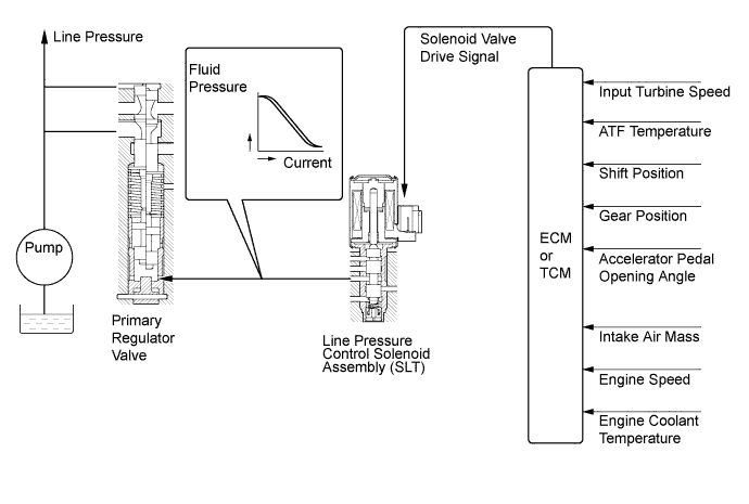
Line Pressure Control
-
In order to obtain a predetermined line pressure characteristic in accordance with each sensor signal, the ECM or TCM activates the shift solenoid valve SLT to regulate the throttle pressure.
-
This makes it possible for the primary regulator valve to precisely and minutely control the line pressure in accordance with the engine output, thus providing smoother shift characteristics.
-
-
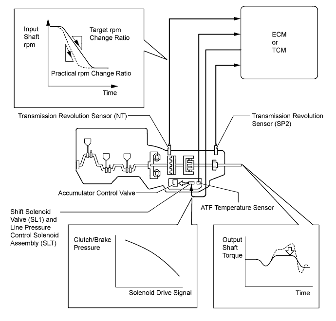
Clutch Pressure Optimal Control
-
The ECM or TCM monitors the signals from various types of sensors, such as the transmission revolution sensor (NT), allowing shift solenoid valves SL1 and SLT to minutely control the clutch pressure in accordance with engine output and driving conditions. As a result, smooth shift characteristics are achieved.
-
-
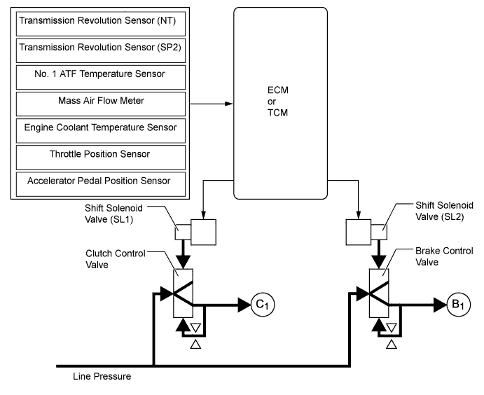
Clutch to Clutch Pressure Control
-
This control is used for shifting from 4th to 5th gear and from 5th to 4th gear.
-
The ECM or TCM actuates shift solenoid valves SL1 and SL2 in accordance with various signals. The output from these shift solenoid valves acts directly on control valves B1and C1in order to regulate the line pressure that acts on the B1brake and C1clutch.
-
As a result, high response and excellent shift characteristics have been achieved.
-
-
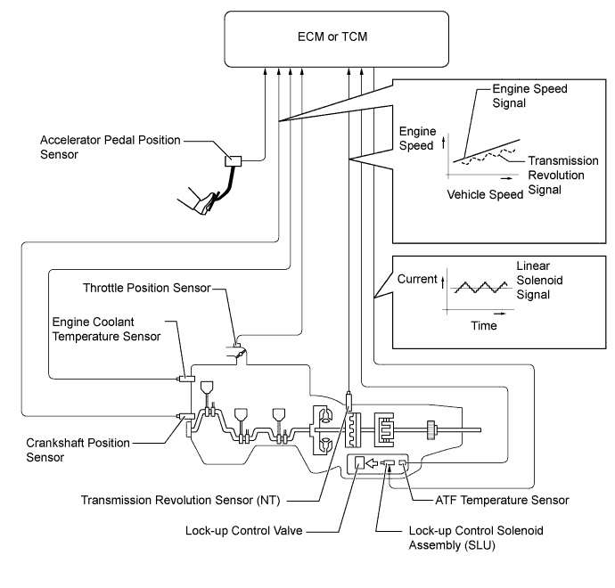
Lock-up Timing Control
-
The ECM or TCM operates the lock-up timing control in order to improve the fuel consumption performance in the top gear when the shift lever is in D or in the S5 or S4 range.
Lock-up Timing Control Operation Gear Shift Lever Position or Shift Range D, S5 S4 1st X X 2nd X X 3rd X X 4th X ○ 5th ○ - Tech Tips
○: Operates
X: Does not operate
-
-
Flex Lock-up Clutch Control
-
In the low-to-mid-speed range, this flex lock-up clutch control regulates the shift solenoid valve SLU to provide an intermediate mode between the on and off operations of the lock-up clutch in order to improve the energy transmitting efficiency in this range. As a result, the operating range of the lock-up clutch has been increased and fuel economy has been improved. The flex lock-up clutch control operates in 3rd, 4th and 5th gears when the shift lever is in D or in the S5 range, and in 3rd* and 4th gears when the shift lever is in the S4 range.
-
*: Models with 1KD-FTV engine
-
-
Even when the vehicle is decelerating (the accelerator pedal is released), the flex lock-up clutch control operates. Therefore, the fuel-cut area of the engine has been expanded and fuel economy has been improved.
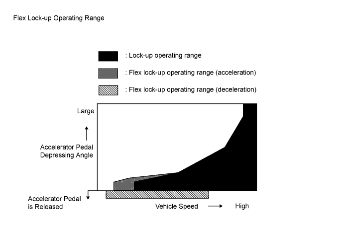
Flex Lock-up Clutch Control Operation (Models with 1GR-FE Engine:) Gear Shift Lever Position or Shift Range D, S5 S4 1st X X 2nd X X 3rd ○*1 X 4th ○ ○*2 5th ○ - Tech Tips
○: Operates
X: Does not operate
*1: Flex lock-up clutch control operates during acceleration.
*2: Flex lock-up clutch control operates during deceleration.
Flex Lock-up Clutch Control Operation (Models with 1KD-FTV Engine:) Gear Shift Lever Position or Shift Range D, S5 S4 1st X X 2nd X X 3rd ○* ○* 4th ○ ○* 5th ○ - Tech Tips
○: Operates
X: Does not operate
*: Flex lock-up clutch control operates during deceleration.
-
-
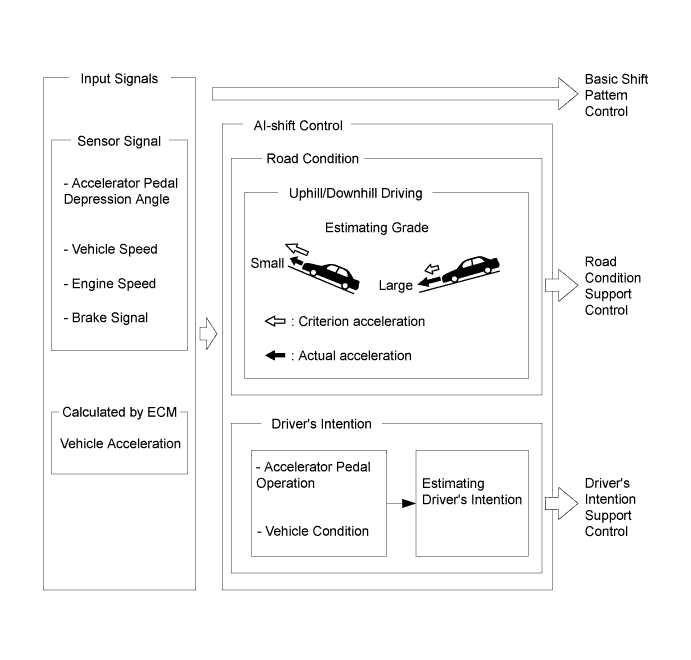
Artificial Intelligence-shift Control (AI-shift Control)
-
The AI-shift control determines optimal transmission control based on input signals and automatically changes the shift pattern. As a result, a high caliber of transmission operation is achieved.
-
The AI-shift control includes a road condition support control and a driver's intention support control.
-
The AI-shift control is effected only with the shift lever in D, based on the accelerator pedal and brake operation data. The AI-shift control will be canceled when the shift lever is moved to a position other than D.
-
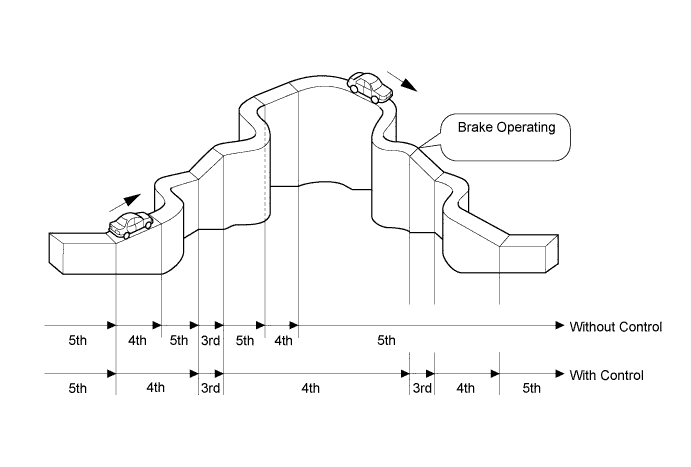
Under road condition support control, the ECM or TCM identifies the throttle valve opening angle, the accelerator pedal opening angle and the vehicle speed to determine whether the vehicle is being driven uphill or downhill. To achieve an optimal drive force while driving uphill, this control prevents the transmission from upshifting to 4th or 5th gear. To achieve an optimal engine braking effect while driving downhill, this control automatically downshifts the transmission to 4th or 3rd gear.
-
The driver's intention support control is estimated based on the accelerator pedal operation and vehicle condition, and a shift pattern that is well-suited to the driver is selected.
-
-
Multi-mode Automatic Transmission
-
A multi-mode automatic transmission is designed to allow the driver to switch the shift ranges (a multi-mode transmission is not for manually selecting single gears). After moving the shift lever to S, the driver can select the desired shift range by moving the shift lever to "+" (forwards) or "-" (backwards). Thus, the driver is able to shift gears with a manual-like feel.
-
The driver selects S mode by engaging the shift lever. At this time, the S4 range is selected (during AI-shift control, the shift range that has the currently controlled gear position as the maximum usable gear position will be displayed). Then, the shift range changes one at a time, as the driver moves the shift lever to "+" (forwards) or "-" (backwards).
-
Under this control, the ECM or TCM effects optimal shift control within the usable gear position that the driver has selected. As with an ordinary automatic transmission, it shifts to the 1st gear when the vehicle is stopped.
-
Holding the shift lever to "+" (forwards) in S will change the shift range to the S5 range regardless of shift range (S1 to S4).
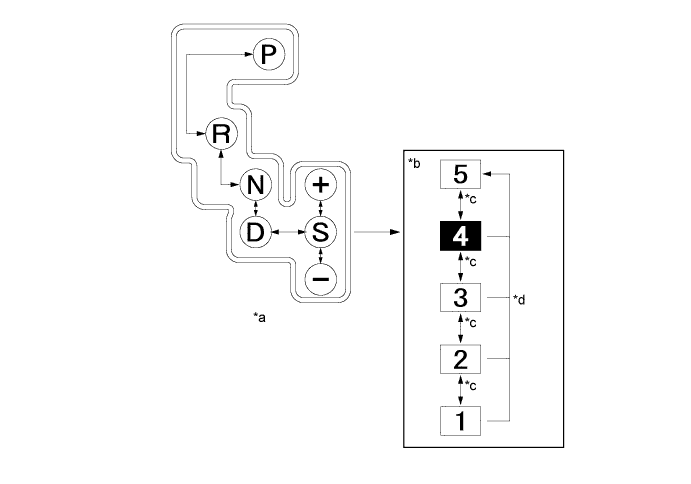
Text in Illustration *a Shift Pattern *b Transition of Shift Range Position *c Moves shift lever to "+" (forwards) or "-" (backwards). *d Holding shift lever to "+" (forwards). 
Default Shift Range - - Usable Gear Chart Shift Range Shift Range Indicator Display Usable Gear S5 5 5th←→4th←→3rd←→2nd←→1st S4 4 4th←→3rd←→2nd←→1st S3 3 3rd←→2nd←→1st S2 2 2nd←→1st S1 1 1st -
When the shift lever is in S, the S mode indicator is shown in the combination meter assembly. The shift range indicator indicates the state of the shift range position that the driver has selected.
-
When the vehicle is being driven at a prescribed speed or higher, any attempt to shift to a lower range by operating the shift lever will not be executed, in order to protect the automatic transmission. In this case, the ECM sounds the multi buzzer in the combination meter assembly twice to alert the driver.
-
-
-
FUNCTION
-
Shift Lock System
-
The shift lock system prevents the shift lever from being moved to any position other than P, unless the engine switch is turned on (IG) and the brake pedal is depressed. This prevents the vehicle from starting off suddenly.
-
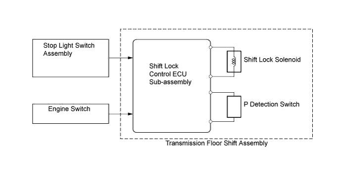
The shift lock system is controlled by the shift lock control ECU sub-assembly, and it has a shift lock function.
-
The shift lock control ECU sub-assembly uses the P detection switch to detect the shift lever position, and receives input signals from the stop light switch assembly and engine switch. Upon receiving these signals, the shift lock control ECU sub-assembly turns on the shift lock solenoid in order to release the shift lock.
-
A shift lock release button, which manually overrides the shift lock mechanism, is used.
-
-
Shift Pattern Select System
-
The shift pattern select system enables the driver to use a 2nd start switch (pattern select switch assembly)*1 or multi-information switch*2 to select the 2nd start mode which allows the vehicle to start off in the 2nd gear, thus making it easy for the vehicle to start off on snowy, sandy or muddy terrain.
-
*1: Models with analog display type combination meter assembly
-
*2: Models with optitron display type combination meter assembly
-
-
When the 2nd start mode is selected while the shift lever is in D or in the S5, S4, S3 or S2 range, the vehicle can start in the 2nd gear. After a start, if the shift lever is in D or in the S5, S4 or S3 range, transmission will shift up automatically into 3rd, 4th or overdrive gears in the normal manner. If the shift lever is in the S2 range, the transmission will continue to operate in the 2nd gear.
-
The 2nd start mode cannot be selected while multi-terrain select is operating.
-
-
-
CONSTRUCTION
-
ATF Warmer (Models for Europe or Chile with 1GR-FE Engine)
-
The ATF warmer uses engine coolant that has been warmed by the engine to warm up the ATF quickly. Consequently, the friction losses of the automatic transmission are quickly reduced, thus improving fuel economy.
-
The ATF warmer has a transmission oil thermostat that changes the route through which the ATF flows.
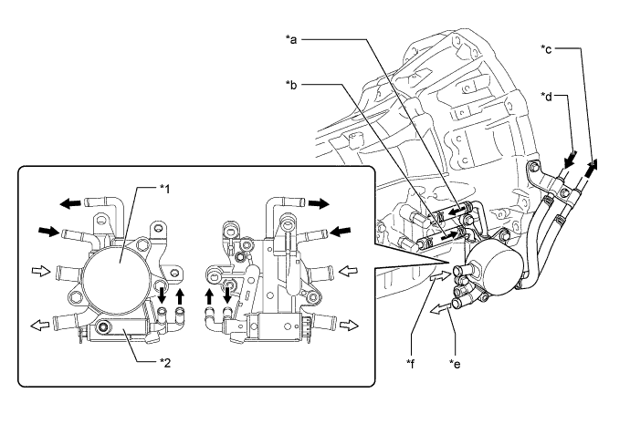
Text in Illustration *1 ATF Warmer *2 Transmission Oil Thermostat *a To Transmission *b From Transmission *c To Radiator (Water-cooled Type ATF Cooler) *d From Radiator (Water-cooled Type ATF Cooler) *e To Engine *f From Heater Core 
ATF Flow 
Engine Coolant Flow -
When the ATF temperature is low, it is heated by the ATF warmer using the engine coolant, and when the ATF temperature is high, it is cooled down by the ATF warmer and radiator (water-cooled type ATF cooler).
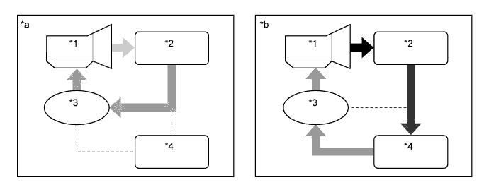
Text in Illustration *1 Transmission *2 ATF Warmer *3 Transmission Oil Thermostat *4 Radiator (Water-cooled Type ATF Cooler) *a ATF Temperature is Low *b ATF Temperature is High -
The transmission oil thermostat consists of a poppet valve, a bypass valve and an element case (contains wax). When the ATF temperature changes from low to high, the wax will expand to start to open the poppet valve and close the bypass valve, thus switching the ATF passages.
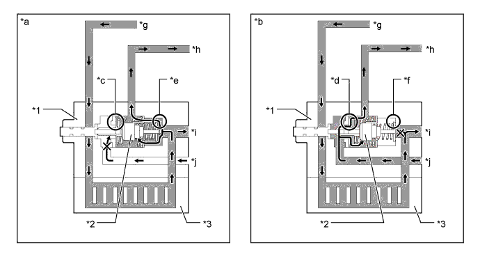
Text in Illustration *1 Transmission Oil Thermostat *2 Element Case (Contains Wax) *3 ATF Warmer - - *a ATF Temperature is Low *b ATF Temperature is High *c Poppet Valve: Closed *d Poppet Valve: Open *e Bypass Valve: Open *f Bypass Valve: Closed *g From Transmission *h To Transmission *i To Radiator (Water-cooled Type ATF Cooler) *j From Radiator (Water-cooled Type ATF Cooler) ATF Flow - -
-
-
Air-cooled Type ATF Cooler (Models with 1GR-FE Engine except Models for Europe or Chile)
-
The air-cooled type ATF cooler cools down the ATF using the cooling fins which are provided on the cooler itself, and is fitted inside the radiator grille so that it can be exposed to the air directly while the vehicle is running.
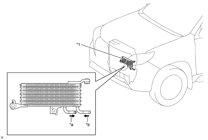
Text in Illustration *1 Air-cooled Type ATF Cooler - - *a To Transmission *b From Radiator (Water-cooled Type ATF Cooler) ATF Flow - - -
The ATF flowing route does not change and ATF always circulates from the transmission to the radiator (water-cooled type ATF cooler) and air-cooled type ATF cooler.
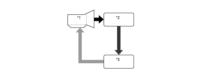
Text in Illustration *1 Transmission *2 Radiator (Water-cooled Type ATF Cooler) *3 Air-cooled Type ATF Cooler - -
-
-
ATF Filling Procedures
-
An ATF filling procedure is used in order to improve the accuracy of the ATF level when the transmission is being repaired or replaced. As a result, the oil filler tube and the oil level gauge used in the conventional automatic transmission have been discontinued, eliminating the need to inspect the fluid level as a part of routine maintenance. For details about the ATF filling procedures, refer to the corresponding Repair Manual for this model.
-
This filling procedure uses a refill plug, overflow plug, No. 2 ATF temperature sensor, and shift position indicator D.
-
ATF filling procedures are different between the models with an air-cooled type ATF cooler and the models without an air-cooled type ATF cooler.
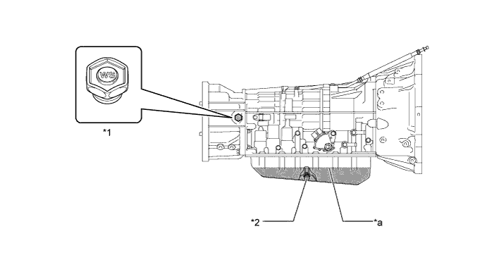
Text in Illustration *1 Refill Plug *2 Overflow Plug *a Proper Level - -
-
-
Torque Converter Clutch Assembly
-
A compact, lightweight and high-capacity torque converter clutch assembly is used. The torque converter clutch supports lock-up clutch control, thus improving fuel economy.
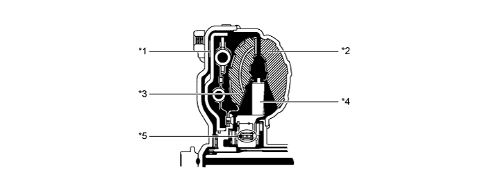
Text in Illustration *1 Lock-up Clutch *2 Pump Impeller *3 Turbine Runner *4 Stator *5 1-way Clutch - -
-
-
Oil Pump
-
The oil pump is operated by the torque converter clutch assembly. It lubricates the planetary gear units and supplies operating fluid pressure for hydraulic control. The front oil pump drive gear is continually driven by the engine via the pump impeller. The pump has sufficient capacity to supply the necessary fluid pressure throughout all speed ranges, as well as in reverse.
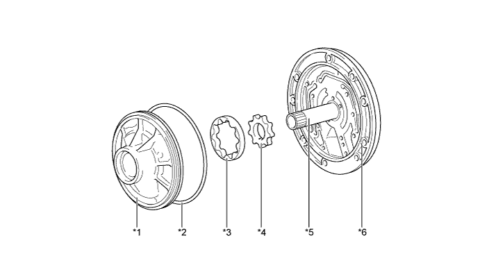
Text in Illustration *1 Front Oil Pump Body Sub-assembly *2 O-ring *3 Front Oil Pump Driven Gear *4 Front Oil Pump Drive Gear *5 Stator Shaft Assembly *6 Oil Pump Cover
-
-
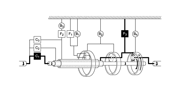
Planetary Gear Unit
-
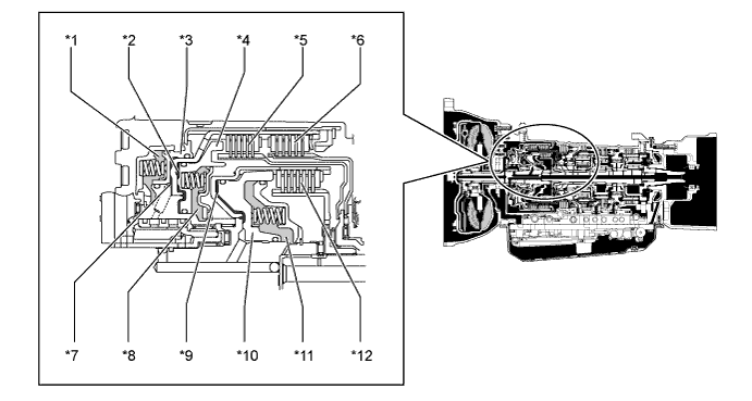
The gear train consists of three multi-plate clutches, four multi-plate brakes, three 1-way clutches, and three sets of planetary gears each consisting of a sun gear, a pinion gear and a ring gear.
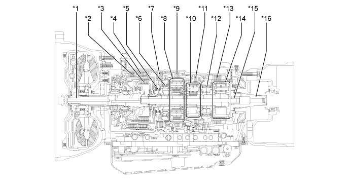
Text in Illustration (Models with 1GR-FE Engine:) *1 Input Shaft *2 No. 2 Clutch (C2)
*3 No. 1 Clutch (C1)
*4 No. 3 Clutch (C3)
*5 No. 2 1-way Clutch (F2)
*6 No. 1 1-way Clutch (F1)
*7 No. 3 Brake (B3)
*8 Front Planetary Gear Assembly *9 No. 1 Brake (B1)
*10 Center Planetary Gear Assembly *11 No. 2 Brake (B2)
*12 No. 3 1-way Clutch (F3)
*13 No. 4 Brake (B4)
*14 Rear Planetary Gear Assembly *15 Intermediate Shaft *16 Output Shaft 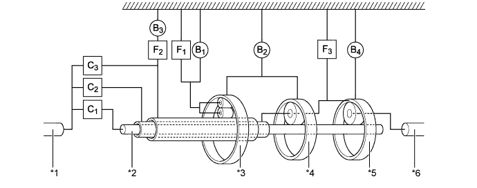
Text in Illustration *1 Input Shaft *2 Intermediate Shaft *3 Front Planetary Gear Assembly *4 Center Planetary Gear Assembly *5 Rear Planetary Gear Assembly *6 Output Shaft
-
-
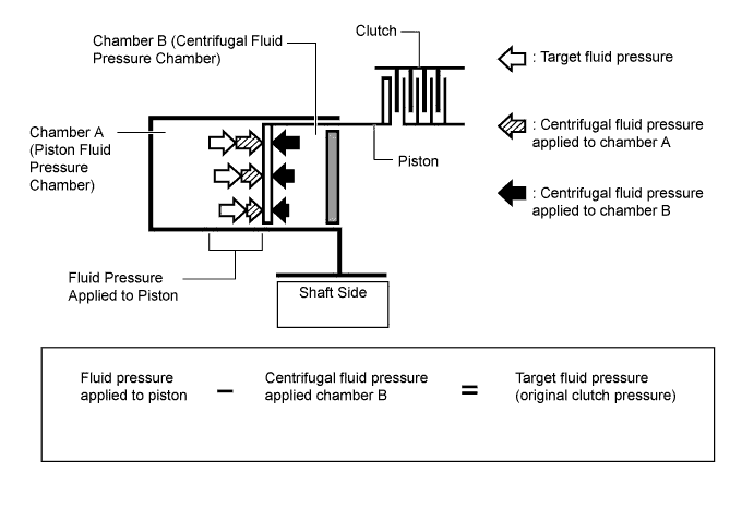
Centrifugal Fluid Pressure Canceling Mechanism
-
The centrifugal fluid pressure canceling mechanism is used on the C1, C2and C3clutches that are applied when shifting 2nd-3rd, 3rd-4th, and 4th-5th.
-
Clutch shifting operation is affected not only by the valve body controlling fluid pressure but also by centrifugal fluid pressure that is present due to fluid in the clutch piston oil pressure chamber. The centrifugal fluid pressure canceling mechanism uses chamber B to reduce the affect applied to chamber A. As a result, smooth shifting with excellent response has been achieved.
Text in Illustration (Models with 1GR-FE Engine:) *1 Chamber B (for C3)
*2 Chamber A (for C2)
*3 Piston (for C3)
*4 Piston (for C2)
*5 No. 2 Clutch (C2)
*6 No. 3 Clutch (C3)
*7 Chamber A (for C3)
*8 Chamber B (for C2)
*9 Chamber A (for C1)
*10 Piston (for C1)
*11 Chamber B (for C1)
*12 No. 1 Clutch (C1)
-
Chamber B is filled by fluid supplied to the shaft for lubrication. As a result of filling chamber B, the same amount of fluid pressure is present on both sides of the piston due to centrifugal force. This cancels the effects of fluid pressure on the piston caused by centrifugal force. Accordingly, it is not necessary to discharge the fluid through the use of a check ball, and highly responsive and smooth shifting characteristics are achieved.
-
-
Transmission Valve Body Assembly
-
The transmission valve body assembly consists of the upper (No. 1 and No. 2) and lower valve bodies and 7 shift solenoid valves.
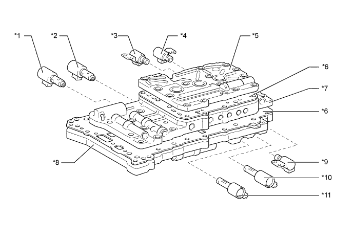
Text in Illustration *1 Line Pressure Control Solenoid Assembly (SLT) *2 Shift Solenoid Valve (SL1) *3 Shift Solenoid Valve DSL (S1) *4 Transmission Solenoid Assembly No. 3 (S2) *5 No. 2 Upper Valve Body *6 Plate *7 No. 1 Upper Valve Body *8 Lower Valve Body *9 Shift Solenoid Valve S4 (SR) *10 Lock-up Control Solenoid Assembly (SLU) *11 Shift Solenoid Valve (SL2) - - 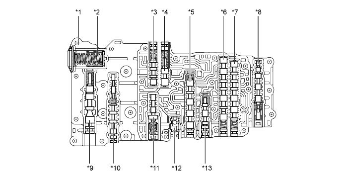
Text in Illustration *1 No. 1 Upper Valve Body *2 B1Accumulator
*3 Clutch Lock Valve *4 Solenoid Modulator Valve *5 3-4 Shift Valve *6 2-3 Shift Valve *7 1-2 Shift Valve *8 B1Apply Control Valve
*9 Secondary Regulator Valve *10 Lock-up Relay Valve *11 Lock-up Control Valve *12 C3Check Valve
*13 Brake Control Valve - - 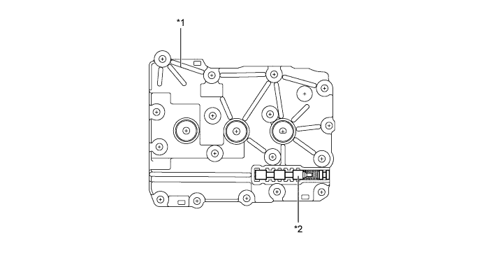
Text in Illustration *1 No. 2 Upper Valve Body *2 Coast Brake Relay Valve 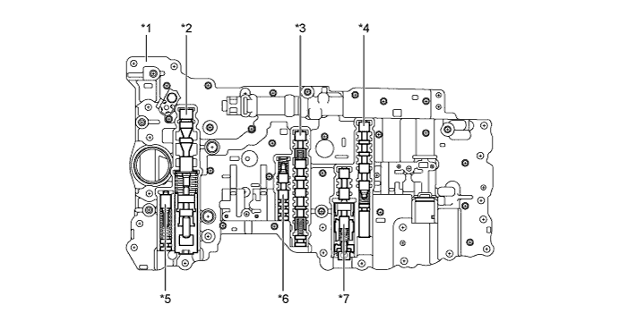
Text in Illustration *1 Lower Valve Body *2 Primary Regulator Valve *3 Clutch Apply Control Valve *4 Sequence Valve *5 SLT Damper *6 Clutch Control Valve *7 Accumulator Control Valve - -
-
-
Shift Solenoid Valves S1, S2 and SR
-
The shift solenoid valve DSL (S1) and shift solenoid valve S4 (SR) are 3-way solenoid valves.
-
A filter is provided at the tip of the solenoid valve to further improve operational reliability.

Text in Illustration *1 Shift Solenoid Valve DSL (S1) *2 Filter *a Line Pressure *b Control Pressure *c Drain - - 
Text in Illustration *1 Shift Solenoid Valve S4 (SR) *2 Filter *a Line Pressure *b Control Pressure *c Drain - - -
The transmission solenoid assembly No. 3 (S2) uses a 2-way solenoid valve.

Text in Illustration *1 No. 3 transmission Solenoid Assembly (S2) *2 Filter *a Line Pressure *b Control Pressure Function of Shift Solenoid Valves S1, S2 and SR Shift Solenoid Valve Function S1 Switches the 2-3 shift valve. S2 Switches the 1-2 shift valve and the 3-4 shift valve. SR Switches the clutch apply control valve.
-
-
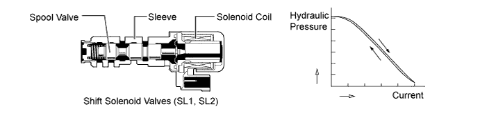
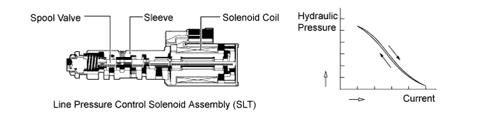
Shift Solenoid Valves SL1, SL2, SLT and SLU
-
In order to provide a hydraulic pressure that is proportional to the current that flows to the solenoid coil, the shift solenoid valves SL1 and SL2 linearly control the clutch pressure based on the signals they receive from the ECM or TCM.
-
In order to provide a hydraulic pressure that is proportional to the current that flows to the solenoid coil, the line pressure control solenoid assembly (SLT) linearly controls the line pressure based on the signals it receives from the ECM or TCM.
-
In order to provide a hydraulic pressure that is proportional to the current that flows to the solenoid coil, the lock-up control solenoid assembly (SLU) linearly controls the lock-up clutch engagement pressure based on the signals it receives from the ECM or TCM.
Function of Shift Solenoid Valves SL1, SL2, SLT and SLU Shift Solenoid Valve Function SL1
-
C1clutch pressure control
-
Accumulator back pressure control
SL2 B1, B2and B4brake pressure control
SLT
-
Line pressure control
-
Accumulator back pressure control
SLU
-
Lock-up clutch pressure control
-
Accumulator back pressure control
-
-
-
ATF Temperature Sensor
-
The No. 1 ATF temperature sensor (THO1) is used for hydraulic pressure control. This sensor is used for revision of the pressure that is used to apply clutches and brakes in the transmission. This helps to ensure smooth shift quality.
-
The No. 2 ATF temperature sensor (THO2) is used as a basis for modifying the ECT shift timing control when the ATF temperature is high. It is also used for the ATF temperature warning light and the ATF temperature warning message.
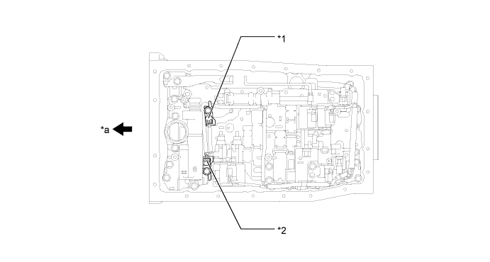
Text in Illustration *1 No. 1 ATF Temperature Sensor *2 No. 2 ATF Temperature Sensor *a Front - -
-
-
Transmission Revolution Sensors
-
This automatic transmission uses a transmission revolution sensor (for NT signal) and a transmission revolution sensor (for SP2 signal). Thus, the ECM or TCM can detect the timing of the shifting of the gears and appropriately control the engine torque and hydraulic pressure in response to various conditions.
-
These speed sensors are the pick-up coil type.
-
The transmission revolution sensor (for NT signal) detects the input speed of the transmission. The reverse clutch piston sub-assembly is used as the timing rotor for this sensor.
-
The transmission revolution sensor (for SP2 signal) detects the speed of the output shaft. The parking lock gear on the rear planetary gear is used as the timing rotor for this sensor.
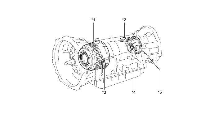
Text in Illustration *1 Reverse Clutch Piston Sub-assembly *2 Transmission Revolution Sensor (SP2) *3 Transmission Revolution Sensor (NT) *4 Rear Planetary Gear *5 Parking Lock Gear - -
-
-
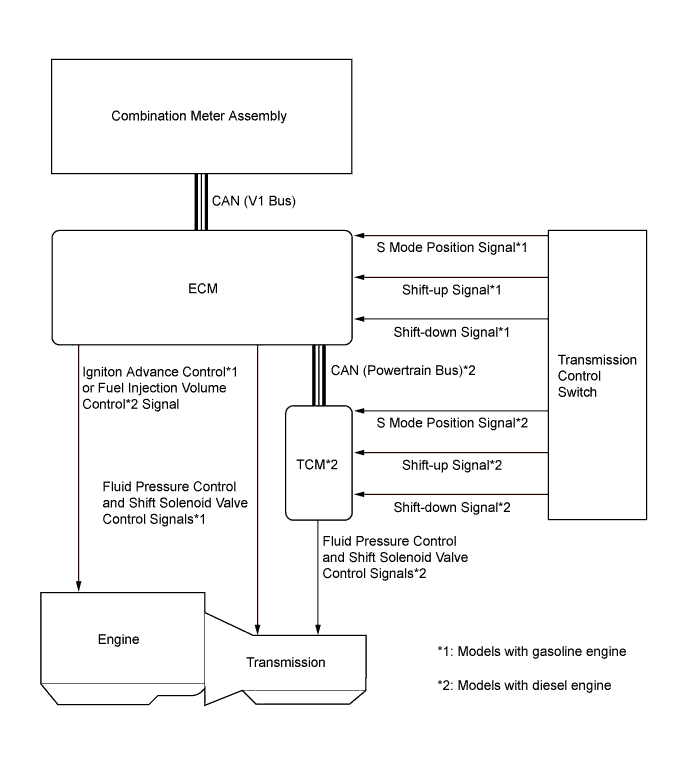
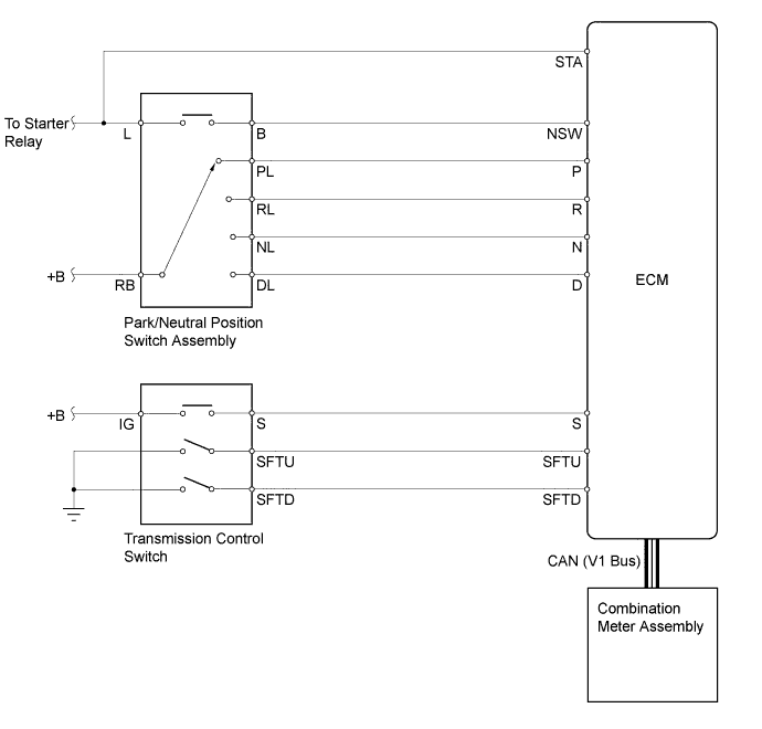
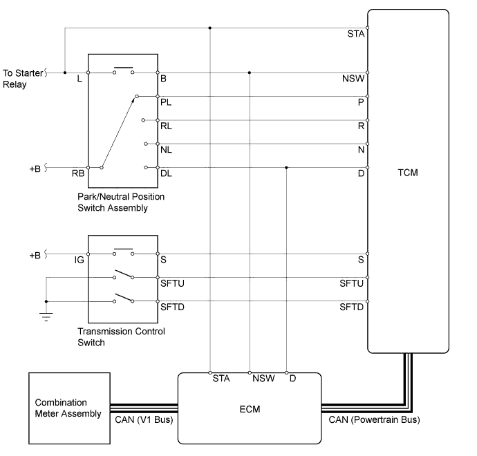
Park/Neutral Position Switch Assembly and Transmission Control Switch (Models with Gasoline Engine)
-
The ECM uses the park/neutral position switch assembly and the transmission control switch to detect the shift lever position.
-
The park/neutral position switch assembly sends the P, R, N, D and NSW signals to the ECM. The ECM also sends signals to the shift position indicator "P, R, N, and D" in the combination meter assembly via CAN.
-
The transmission control switch is installed inside the transmission floor shift assembly to detect the S mode position and to inform the ECM. The ECM turns on the S mode indicator in the combination meter assembly.
-
The transmission control switch detects whether the shift lever is in D or S, and detects the operating conditions of the shift lever ["+" (forwards) or "-" (backwards)] if the S mode is selected, and sends signals to the ECM. At this time, the ECM turns on the shift range indicator in the combination meter assembly via CAN for the selected shift range.
-
-
Park/Neutral Position Switch Assembly and Transmission Control Switch (Models with Diesel Engine)
-
The TCM and ECM use the park/neutral position switch assembly and the transmission control switch to detect the shift lever position.
-
The park/neutral position switch assembly sends the P, R, N, D and NSW signals to the TCM and the D and NSW signals to the ECM. The TCM and ECM also send signals to the shift position indicator "P, R, N, and D" in the combination meter assembly via CAN.
-
The transmission control switch is installed inside the transmission floor shift assembly to detect the S mode position and to inform the TCM. The TCM and ECM turn on the S mode indicator in the combination meter assembly.
-
The transmission control switch detects whether the shift lever is in D or S, and detects the operating conditions of the shift lever ["+" (forwards) or "-" (backwards)] if the S mode is selected, and sends signals to the TCM. At this time, the TCM and ECM turn on the shift range indicator in the combination meter assembly via CAN for the selected shift range.
-
-
Shift Control Mechanism
-
A gate type shift lever that uses a transmission control cable is used.
-
The shift control mechanism consists of a transmission floor shift assembly and a transmission control cable assembly.
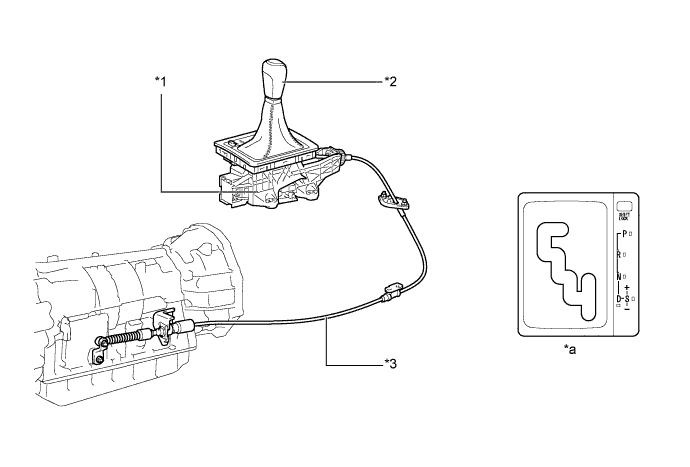
Text in Illustration *1 Transmission Floor Shift Assembly *2 Shift Lever Knob *3 Transmission Control Cable Assembly - - *a Shift Pattern - -
-
-
-
OPERATION
-
Transmission Power Flow
Operating Condition Shift Lever or Gear Range Position Gear Position Shift Solenoid Valve Clutch Brake 1-way Clutch S1 S2 SR SL1 SL2 SLU C1
C2
C3
B1
B2
B3
B4
F1
F2
F3
P Park On Off Off Off On Off - - - - - - - - - - R* Reverse On Off Off Off On Off - - ○ (○) - - ○ ○ - - N Neutral On Off Off Off On Off - - - - - - - - - - D, S5 1st On Off Off Off On Off ○ - - - - - - - - ○ 2nd On On Off Off On Off ○ - - - - ○ - ○ ○ - 3rd Off On Off Off On Off ○ - ○ - - ● - ○ - - 4th* Off Off Off Off On Off ○ ○ ● - - ● - - - - 5th* Off Off On On Off On - ○ ○ ○ - ● - - - - S4 1st On Off Off Off On Off ○ - - - - - - - - ○ 2nd On On Off Off On Off ○ - - - - ○ - ○ ○ - 3rd Off On Off Off On Off ○ - ○ - - ● - ○ - - 4th* Off Off Off Off On On ○ ○ ● - - ● - - - - S3 1st On Off Off Off On Off ○ - - - - - - - - ○ 2nd On On Off Off On Off ○ - - - - ○ - ○ ○ - 3rd* Off On Off Off Off Off ○ - ○ (○) - ● - ○ - - S2 1st On Off Off Off On Off ○ - - - - - - - - ○ 2nd* On On On Off Off Off ○ - - - (○) ○ - ○ ○ - S1 1st* On Off Off Off Off Off ○ - - - - - (○) - - ○ Tech Tips
○: Operates
●: Operates but is not related to power transmission
(○): Operates during engine braking
-: Does not operate
*: Engine braking occurs
-
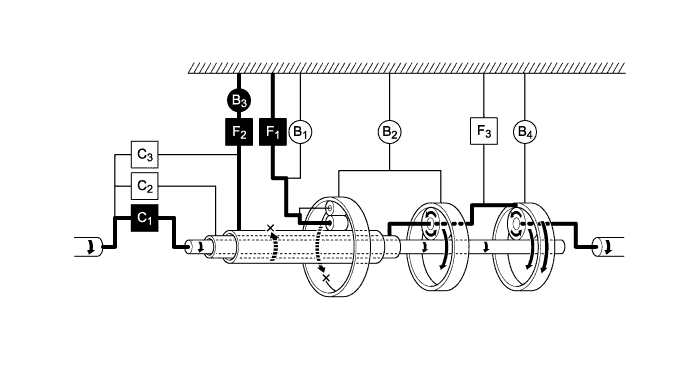
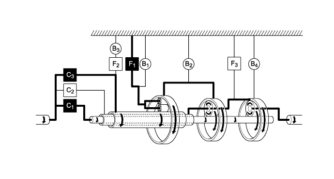
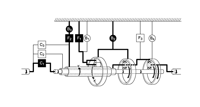
1st Gear (Shift Lever in D or in S5, S4, S3 or S2 Range)
Text in Illustration Operates - - -
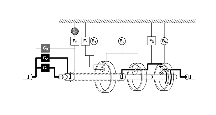
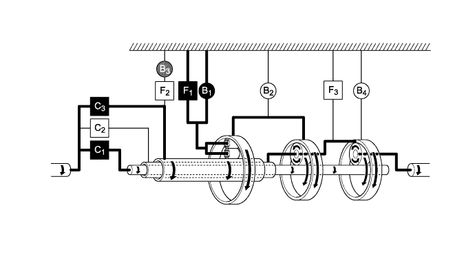
2nd Gear (Shift Lever in D or in S5, S4 or S3 Range)
Text in Illustration Operates - - -
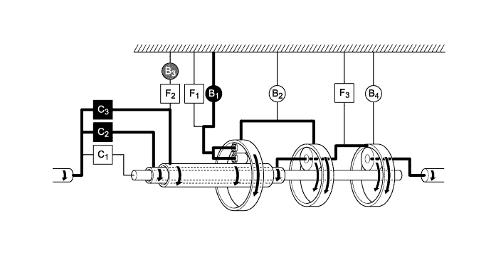
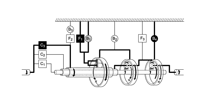
3rd Gear (Shift Lever in D or in S5 or S4 Range)
Text in Illustration Operates - - -
4th Gear (Shift Lever in D or in S5 or S4 Range)
Text in Illustration Operates 
Operates but is not related to power transmission -
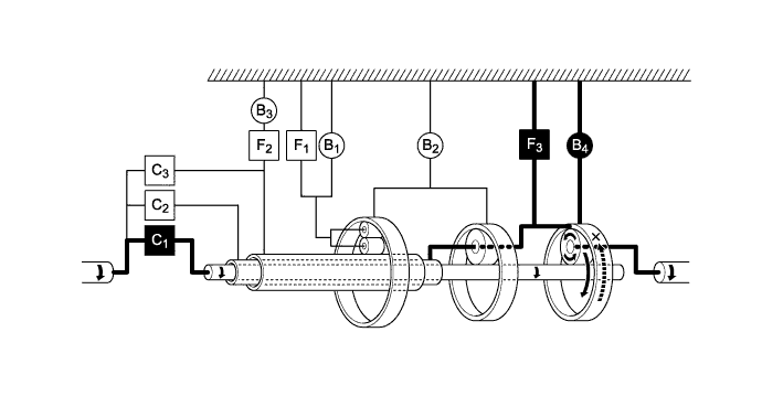
5th Gear (Shift Lever in D or in S5 Range)
Text in Illustration Operates Operates but is not related to power transmission -
1st Gear (Shift Lever in S1 Range)
Text in Illustration Operates - - -
2nd Gear (Shift Lever in S2 Range)
Text in Illustration Operates - - -
3rd Gear (Shift Lever in S3 Range)
Text in Illustration Operates Operates but is not related to power transmission -
Reverse Gear (Shift Lever in R)
Text in Illustration Operates 
Operates during engine braking
-
-
-
FAIL-SAFE
-
The fail-safe function minimizes the loss of operability when an abnormality occurs in a sensor or a solenoid.
Fail-safe Control List Malfunction Part Function Transmission Revolution Sensor (NT)
-
During a transmission revolution sensor (NT) malfunction, shift control is effected based on the transmission revolution sensor (SP2) signal.
-
During a transmission revolution sensor (NT) malfunction, upshifting to 5th, AI-shift and flex lock-up clutch control are prohibited.
Transmission Revolution Sensor (SP2)
-
During a transmission revolution sensor (SP2) malfunction, shift control is effected based on the transmission revolution sensor (NT) signal.
-
During a transmission revolution sensor (SP2) malfunction, upshifting to 5th, AI-shift and flex lock-up clutch control are prohibited.
No. 1 ATF Temperature Sensor (THO1) During a No. 1 ATF temperature sensor malfunction, upshifting to 5th and flex lock-up clutch control are prohibited. Shift Solenoid Valves S1, S2 and SR
-
When one of the shift solenoid valves listed left malfunctions, current to the failed shift solenoid valve is cut off.
-
Shift control is changed to a fail-safe mode to shift gears using the normal shift solenoid valves to allow continued driving.
Shift Solenoid Valves SL1 and SL2 During a shift solenoid valve SL1 or SL2 malfunction, upshifting to 5th and flex lock-up clutch control are prohibited. Line Pressure Control Solenoid Assembly (SLT) During a line pressure control solenoid assembly (SLT) malfunction, the current to the shift solenoid valve is stopped. Because this stops line pressure optimal control, the shift shock will increase. However, shifting is effected based on normal clutch pressure control. Lock-up Control Solenoid Assembly (SLU) During a lock-up control solenoid assembly (SLU) malfunction, the current to the shift solenoid valve is stopped. Because this stops lock-up control and flex lock-up control, fuel economy decreases. -
-
-
DIAGNOSIS
-
When the ECM or TCM detects a malfunction, it makes a diagnosis and memorizes the failed section. Furthermore, the ECM or TCM illuminates or blinks the MIL in the combination meter assembly to inform the driver.
-
The ECM or TCM will also store the Diagnostic Trouble Codes (DTCs) of the malfunctions.
-
The DTCs can be read by connecting an Global TechStream (GTS) to the DLC3.
-
For details, refer to the Repair Manual.
-