ECD SYSTEM DETAILS
-
FUNCTION OF MAIN COMPONENTS
-
The main components of the engine control system are as follows:
Component Outline Quantity Function ECM Forest 1 The ECM effects overall control of the engine control system to suit the operating conditions of the engine in accordance with the signals provided by the sensors. Injector Driver DC/DC Converter 1 The injector driver is used to drive the injector at high speeds. The injector driver has achieved high-speed driving under high fuel pressure conditions through the use of a DC/DC converter that provides a high voltage, quick-charging system. Turbo Pressure Sensor Semiconductor Silicon Chip Type 1 This sensor uses built-in semiconductors to detect the intake manifold pressure. Atmospheric Pressure Sensor Semiconductor Silicon Chip Type 1 This sensor, which is built into the ECM, uses semiconductors to detect the atmospheric pressure. Fuel Pressure Sensor Semiconductor Strain Gauge Type 1 This sensor uses built-in semiconductors to detect the internal pressure of the common-rail. Pressure Discharge Valve Solenoid Type 1 The pressure discharge valve regulates the fuel pressure. Crank Position Sensor Pick-up Coil Type
(Rotor Teeth/36-2)
1 This sensor detects the engine speed and performs the cylinder identification. Camshaft Position Sensor Pick-up Coil Type
(Rotor Teeth/5)
1 This sensor performs the cylinder identification. Intake Mass Air Flow Meter Sub-assembly Hot-wire Type 1 This sensor uses a built-in hot-wire to directly detect the intake air mass. Intake Air Temperature Sensor
(Built into Intake Mass Air Flow Meter Sub-assembly)
Thermistor Type 1 This sensor detects the intake air temperature by means of an internal thermistor. Intake Air Temperature Sensor
(Intercooler Outlet)
Thermistor Type 1 This sensor detects the intake air temperature past the intercooler. Engine Coolant Temperature Sensor Thermistor Type 1 This sensor detects the engine coolant temperature by means of an internal thermistor. Fuel Temperature Sensor Thermistor Type 1 This sensor detects the fuel temperature in the supply pump by means of an internal thermistor. Throttle Position Sensor Non-contact Type 1 This sensor detects the diesel throttle valve opening angle. Accelerator Pedal Position Sensor Non-contact Type 1 This sensor detects the amount of pedal effort applied to the accelerator pedal. Nozzle Vane Position Sensor Non-contact Type 1 This sensor detects the nozzle vane position. Oil Pressure Sensor*1 Semiconductor Silicon Chip Type 1 This sensor detects the engine oil pressure. Oil Pressure Switching Valve*1 Solenoid Type 1 The oil pressure switching valve controls the engine oil pressure in 2 stages. Suction Control Valve (SCV) Linear Solenoid Valve 1 The SCV position is controlled by the signals from the ECM, and a fuel volume that suits the SCV position is drawn into the pumping portion (plunger portion). Glow Plug Controller*1 Pulse Width Modulation (PWM) Driver 1 The glow plug controller controls the length of time for which the current is applied to the glow plug assemblies in accordance with the ECM signal. Injector Assembly 10-hole, Piezo Type*1 4 The injector injects the fuel to the combustion chamber in accordance with the ECM signals via the EDU. 8-hole, Solenoid Type*2
-
*1: Models compliant with EURO 5+ emission regulations
-
*2: Except models compliant with EURO 5+ emission regulations
-
-
-
SYSTEM CONTROL
-
The engine control system has the following features. The ECM controls these systems:
System Outline Fuel Injection Volume Control Based on the signals received from the sensors, the ECM determines the fuel injection volume in accordance with the engine condition. Fuel Injection Timing Control Based on the signals received from the sensors, the ECM determines the fuel injection timing in accordance with the engine condition. During Starting Control To facilitate startability, the ECM optimally controls the injection volume and injection timing during starting. Idle Speed Control The ECM determines the idle speed in accordance with the engine condition, and controls the fuel injection volume in order to maintain the target idle speed. Fuel Pressure Control Based on the signals received from the sensors, the ECM controls fuel pressure using the Suction Control Valve (SCV) and pressure discharge valve in accordance with engine operating conditions. Pilot Injection Control Based on the signals received from the sensors, the ECM determines pilot injection volume/timing and interval (between pilot injection and main injection) in accordance with the engine condition. Glow Plug Control The ECM sends signals to the glow plug controller in accordance with engine conditions. Based on the signals, the glow plug controller controls the length of time for which the current is applied to the glow plug assemblies in each cylinder.*1 The ECM controls the length of time for which the current is applied to the glow plug assemblies, in accordance with the engine coolant temperature.*2 Diesel Throttle Control
-
Controls the diesel throttle valve opening angle in accordance with the engine condition.
-
Fully closes the diesel throttle valve in order to reduce the vibration when the engine is stopped.
Swirl Control
-
Based on the signals received from the sensors, the ECM controls the vacuum that is directed to the actuator via the VSVs, in order to open and close the valve.
-
Controls the valve opening in three stages: fully open, semi-open, and fully closed.
Turbocharger Control Based on the signals received from the sensors, the ECM controls the actuator in accordance with the engine condition. Air Conditioning Cut-off Control*3 By controlling the air conditioning compressor on or off in accordance with the engine condition, driveability is maintained. Starter Control*4 Once the engine switch is pushed, this control continues to operate the starter until the engine is started. Engine Immobiliser Prohibits fuel injection if an attempt is made to start the engine with an invalid ignition key. Fuel Pump Control*5 The ECM operates the fuel pump to optimally control the transfer of the fuel in the fuel tank. Oil Maintenance Management System*6 When the ECM determines engine oil and oil filter deterioration, the engine oil change reminder light turns on to inform the driver. Engine Mount Control When the engine speed is low and the vehicle is operating at a low speed, this control utilizes vacuum to soften the engine mount characteristics in order to restrain the engine vibration at idle. Power Heater Control*7 By controlling the power heater magnetic clutch on or off in accordance with the engine condition. Oil Pressure Control System*1 The ECM controls the engine oil pressure in 2 stages to reduce friction losses. Diagnosis When the ECM detects a malfunction, it diagnoses and memorizes the failed section. Fail-safe When the ECM detects a malfunction, it stops or controls the engine in accordance with the data already stored in the memory. Brake Override System The driving torque is restricted when the brake pedal is depressed while the accelerator pedal is depressed. (For the Activation Conditions and Inspection Method, refer to the Repair Manual.)
-
*1: Models compliant with EURO 5+ emission regulations
-
*2: Except models compliant with EURO 5+ emission regulations
-
*3: Models with air conditioning
-
*4: Models with entry and start system
-
*5: Models with dual fuel tank
-
*6: Models for Europe
-
*7: Cold area specification models
-
-
-
FUNCTION
-
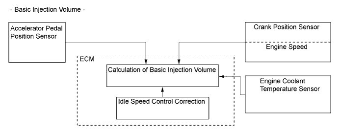
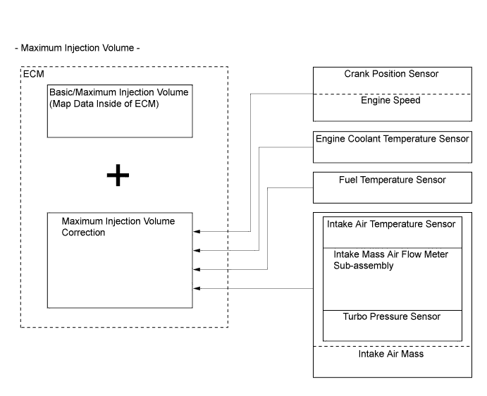
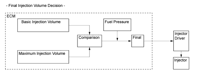
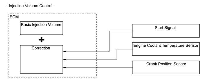
Fuel Injection Volume Control
-
The ECM calculates 2 types of values: the basic injection volume and the maximum injection volume. Then, the ECM compares the basic and maximum injection volumes, and determines the smaller calculated value to be the final injection volume.
-
-
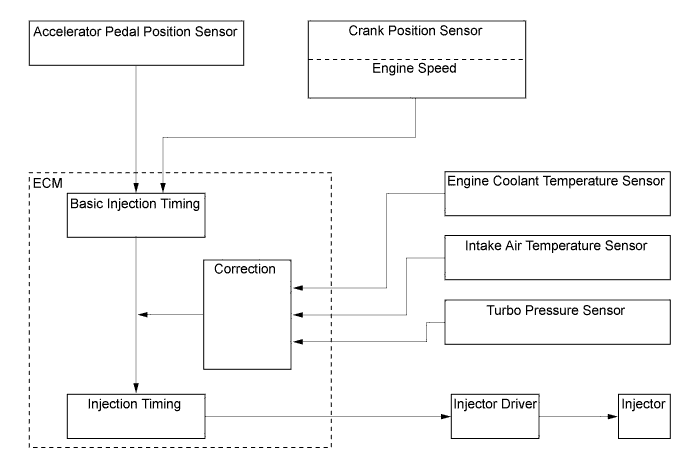
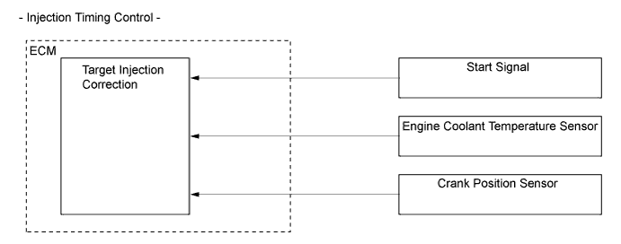
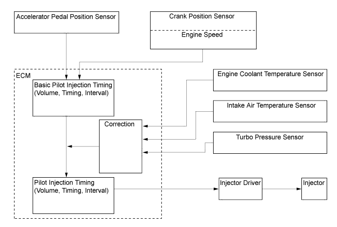
Fuel Injection Timing Control
-
Fuel injection timing is controlled as shown below:
-
-
During Starting Control
-
The starting injection volume is determined by adjusting the basic injection volume in accordance with the starter on signals (on time) and engine coolant temperature sensor signals and engine speed signal. When the engine is cold, the engine coolant temperature will be lower and the injection volume will be greater.
-
To determine the starting injection timing, the target injection timing is corrected in accordance with the starter signals, engine coolant temperature, and engine speed. When the engine coolant temperature is low, if the engine speed is high, the injection timing is advanced.
-
-
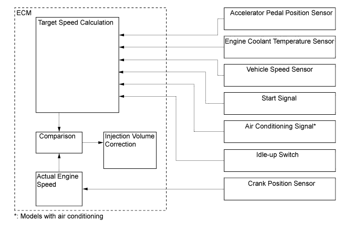
Idle Speed Control
-
Idle speed control correction is controlled as shown below:
-
-
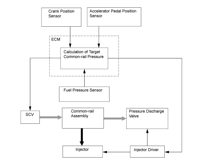
Fuel Pressure Control
-
The ECM calculates the target injection pressure (32 MPa to 160 MPa) based on the signals from the accelerator pedal position sensor and the crank position sensor. To control fuel pressure, signals sent to the Suction Control Valve (SCV) of the supply pump assembly regulate the suction volume, and signals sent to the pressure discharge valve of the common-rail regulate the discharge volume, so that the pressure detected by the fuel pressure sensor matches the target injection pressure.
-
-
Pilot Injection Control
-
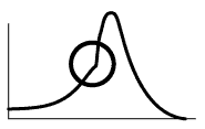
Pilot injection is a method that provides an auxiliary fuel injection before the main fuel injection takes place. The purpose of pilot injection is to gently start the combustion of the fuel of the main injection in order to reduce combustion noise.
State Pilot Injection Ordinary Injection Fuel Injection 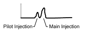
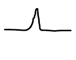
Combustion Pressure 
-
During pilot injection, the pilot injection volume, timing, and interval (between pilot injection and main injection) are controlled as shown below:
-
-
Glow Plug Control
-
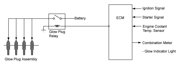
Except on the models compliant with EURO 5+ emission regulations, the ECM controls the length of time for which the current is applied to the glow plug relay when the engine starts in accordance with engine coolant temperature to control the length of time for which the current is applied to the glow plug assemblies.
-
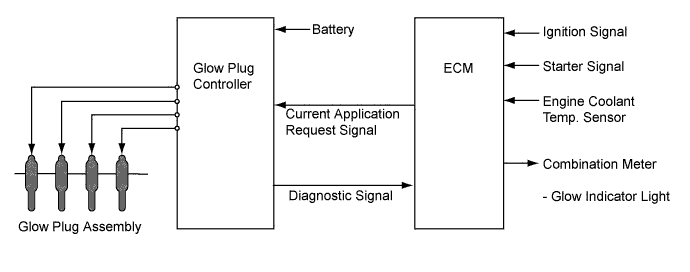
On the models compliant with EURO 5+ emission regulations, the ECM sends a signal to the glow plug controller, and the glow plug controller independently controls the length of time for which the current is applied to the glow plug assemblies in each cylinder in accordance with engine conditions. By independently and precisely controlling the temperature inside each cylinder, low emissions are achieved.
-
-
Diesel Throttle Control
-
The ECM controls the opening of the diesel throttle valve to reduce the noise caused when idling and decelerating, and the noise and vibrations caused when stopping the engine.
-
-
Swirl Control
-
The ECM controls the swirl control valve position to improve torque in the low engine speed range and to optimize exhaust emissions.
-
-
Turbocharger Control
-
The ECM controls the nozzle vane position, in order to obtain the calculated target turbo pressure appropriate to the engine operating conditions.
-
-
Starter Control (Models with Entry and Start System)
-
Depressing the clutch pedal*1 or brake pedal*2 and pressing the engine switch once will operate the starter continuously until the engine has started completely. Operability and the starting operation have thereby been improved.
-
*1: Models with manual transmission
-
*2: Models with automatic transmission
-
-
If the power management control ECU detects a start signal, it will monitor the engine speed signal (NE) from the ECM and operate the starter continuously until it determines that the engine has started completely.
-
-
Fuel Pump Control (Models with Dual Fuel Tank)
-
The fuel pump control system transfers fuel from the sub fuel tank to the main fuel tank.
-
-
Oil Maintenance Management System (Models for Europe)
-
An oil maintenance management system is used. This system determines the deterioration conditions of the engine oil and illuminates an engine oil change reminder light to inform the driver when the engine oil and the oil filter must be changed. Accordingly, maintenance intervals (30000 km maximum) that correspond to the actual deterioration conditions of the engine oil have been achieved.
-
This system indirectly determines the deterioration of the engine oil based on the information provided by the ECM.
-
-
Engine Mount Control
-
When the engine is idling and the vehicle is operating at a low speed, this engine mount utilizes the vacuum from the vacuum pump (for the engine) to move the diaphragm in the mount, which switches the passages for the fluid (water) that is sealed in. By softening the dampening characteristics of the mount in this manner, this mount restrains engine vibration.
-
-
Power Heater Control (Cold Area Specification Models)
-
A viscous type power heater is used. The power heater increases the engine coolant temperature by utilizing the shear heat of the silicon oil and by increasing the engine load.
-
-
Oil Pressure Control System (Models Compliant with EURO 5+ Emission Regulations)
-
The ECM controls the engine oil pressure in 2 stages in accordance with the engine conditions. As a result, energy loss caused by oil pump operation is reduced to achieve improved fuel efficiency.
-
-
-
CONSTRUCTION
-
ECM
-
The forest type CPU of the ECM is used to increase the speed for processing the signals.
-
-
Injector Driver
-
The injector driver is used to drive the injector at high speeds. The injector driver has achieved high-speed driving under high fuel pressure conditions through the use of a DC/DC converter that provides a high voltage, quick-charging system.
-
The ECM constantly monitors the injector driver and stops the engine when an abnormal condition is detected.
-
-
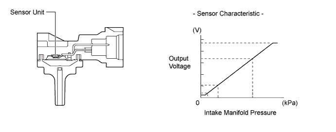
Turbo Pressure Sensor
-
The turbo pressure sensor consists of a semiconductor which utilizes the characteristics of a silicon chip that changes its electrical resistance when pressure is applied to it. The sensor converts the intake air pressure into an electrical signal, and sends it to the ECM in an amplified form.
-
-
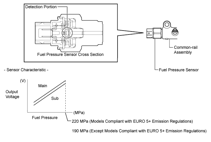
Fuel Pressure Sensor
-
The fuel pressure sensor, which is mounted on the common-rail, outputs a signal that represents the fuel pressure in the common-rail to the ECM in order to constantly regulate the fuel at an optimal pressure.
-
The fuel pressure sensor consists of a semiconductor which utilizes the characteristics of a silicon chip that changes its electrical resistance when pressure is applied to it.
-
The fuel pressure sensor has two circuits (main and sub), which enable the ECM to constantly compare the values detected by the two circuits. As a result, highly precise values can be detected, which also enables a higher level of fail-safe control.
-
-
Pressure Discharge Valve
-
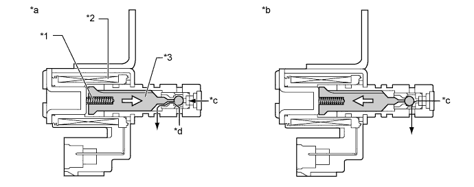
The pressure discharge valve regulates the fuel pressure. In the pressure discharge valve, the plunger opens and closes in accordance with the actuation signals from the injector driver. Thus, it regulates pressure by releasing excess pressure from the common-rail. In addition, it has a pressure reduction function in case of emergency.
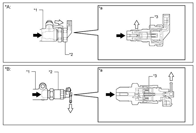
Text in Illustration *A Models Compliant with EURO 5+ Emission Regulations *B Except Models Compliant with EURO 5+ Emission Regulations *1 Common-rail Assembly *2 Pressure Discharge Valve *3 Plunger - - *a Pressure Discharge Valve Cross Section - - 
Fuel from Common-rail (High Pressure) 
Fuel to Fuel Tank (Excess Pressure)
-
-
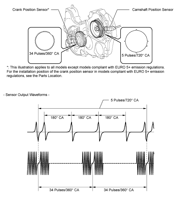
Crank Position Sensor and Camshaft Position Sensor
-
The timing rotor of the crankshaft consists of 34 teeth, with 2 teeth missing. The crank position sensor outputs the crankshaft rotation signals every 10°, and the missing teeth are used to determine the top dead center.
-
To detect the camshaft position, a protrusion that is provided on the timing pulley is used to generate 5 pulses for every 2 revolutions of the crankshaft.
-
-
Intake Mass Air Flow Meter Sub-assembly
-
This engine uses the hot-wire type air flow meter designed for direct electrical measurement of the intake air mass flow.
-
This intake mass air flow meter sub-assembly has a built-in intake air temperature sensor.
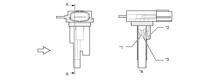
Text in Illustration *1 Platinum Hot-wire Element *2 Intake Air Temperature Sensor *3 Temperature Sensing Element - - *a A - A Cross Section - - Air Flow - -
-
-
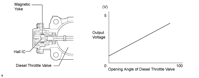
Throttle Position Sensor
-
The throttle position sensor is mounted on the diesel throttle body assembly. To detect the opening angle of the diesel throttle valve, the throttle position sensor converts the magnetic flux density, that changes when the magnetic yoke (located on the same axis as the diesel throttle valve shaft) rotates around the Hall IC, into electric signals to operate the throttle control motor.
-
-
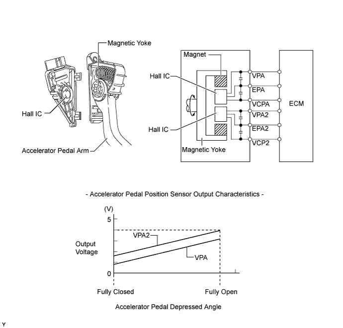
Accelerator Pedal Position Sensor
-
The magnetic yoke that is mounted at the base of the accelerator pedal arm moves around the Hall IC in accordance with the amount of effort that is applied to the accelerator pedal. The Hall IC converts the changes in the magnetic flux that occur at that time into electrical signals, and outputs them in the form of accelerator pedal effort to the ECM.
-
-
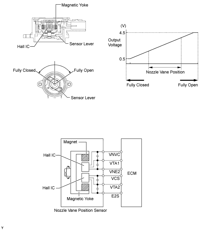
Nozzle Vane Position Sensor
-
The nozzle vane position sensor consists of a Hall IC and a magnetic yoke that rotates in unison with the movement of the linkage that actuates the nozzle vane. The nozzle vane position sensor converts the changes in the magnetic flux that are caused by the rotation of the DC motor (hence, the rotation of the magnetic yoke) into electric signals, and outputs them to the ECM. The ECM determines the actual nozzle vane position from the electric signals in order to calculate the target nozzle vane position.
-
-
Oil Pressure Switching Valve (Models Compliant with EURO 5+ Emission Regulations)
-
The oil pressure switching valve controls the engine oil pressure in accordance with signals from the ECM. Application of current toward the solenoid is controlled and the passage of the engine oil is switched.
Text in Illustration *1 Spring *2 Solenoid *3 Plunger - - *a Oil pressure switching valve is off (current is not applied to the solenoid). *b Oil pressure switching valve is on (current is applied to the solenoid). *c Engine Oil from Oil Pump *d Engine Oil from Sleeve Valve Movement of Plunger - -
-
-
Glow Plug Controller (Models Compliant with EURO 5+ Emission Regulations)
-
The glow plug controller independently controls the length of time for which the current is applied to the glow plug assemblies in accordance with signals from the ECM in each cylinder.
-
The glow plug controller has a function to detect open circuits in the glow plug assemblies. When the glow plug controller detects an open circuit in a glow plug assembly, it sends a signal to the ECM.
-
-
-
OPERATION
-
Glow Plug Control
-
On the models compliant with EURO 5+ emission regulations, glow plug control carries out the following controls:
-
When the starter signal is on with the engine switch on (IG), the ECM sends a signal to the glow plug controller. Based on this signal, the glow plug controller heats the glow plug assemblies rapidly. At this moment, the glow indicator light in the combination meter is illuminated to inform the driver that the glow plug assemblies are being heated.
-
When the engine starts and the starter signal is off, after-glow control is conducted.
-
In accordance with signals from the ECM, the glow plug controller independently applies current via the glow plug assembly in each cylinder to control the temperature of each cylinder independently.
-
When the glow plug controller detects a malfunction in the glow circuit, it sends a diagnostic signal to the ECM.
-
While the catalyst support control is in operation, the ECM sends a signal to the glow plug controller to heat the glow plug assembly. For details of catalyst support control, see the 1KD-FTV Emission Control section.
-
-
Except on the models compliant with EURO 5+ emission regulations, glow plug control carries out the following controls:
-
When the starter signal is on with the engine switch on (IG), the ECM operates the glow plug relay to heat the glow plug assemblies rapidly. At that moment, the glow indicator light in the combination meter is illuminated to inform the driver that the glow plug assemblies are being heated.
-
When the engine starts and the starter signal is off, after-glow control is conducted. When the temperature of the glow plug assembly reaches a predetermined level during after-glow control, it is maintained at a nearly constant level using the self-temperature-controlling function of the glow plug assembly.
-
-
-
Diesel Throttle Control
-
The opening of the diesel throttle valve is controlled by the ECM in accordance with the engine conditions. As a result, the noise that is generated during idling and deceleration, as well as the noise and vibrations that are generated when the engine is stopped, have been reduced and this control makes it possible to recirculate the exhaust gas in accordance with the driving conditions.
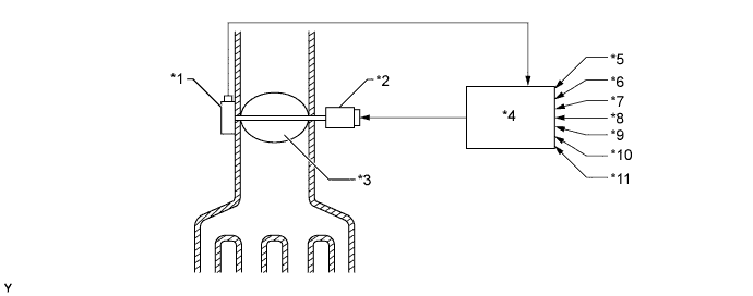
Text in Illustration *1 Throttle Position Sensor *2 Throttle Control Motor *3 Diesel Throttle Valve *4 ECM *5 Engine Speed Signal *6 Vehicle Speed Signal *7 Engine Coolant Temperature Signal *8 Intake Air Temperature Signal *9 Accelerator Pedal Position *10 Intake Air Pressure Signal *11 Ignition Signal - -
-
-
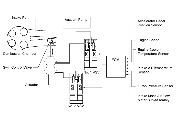
Swirl Control
-
The ECM determines the swirl control valve position based on the engine conditions (engine speed and accelerator pedal effort). Then, it switches the vacuum applied to the actuator diaphragm via the VSV, in order to open and close the swirl control valve.
-
On a cold engine, the ECM fully closes the swirl control valve to reduce the amount of white smoke emissions.
-
In the low engine speed range, the ECM closes the swirl control valve to strengthen the swirl in the combustion chamber, thus promoting the mixture of fuel and air and stabilizing combustion.
-
In the middle engine speed range, the ECM opens the swirl control valve to the semi-open position.
-
In the high engine speed range, the ECM fully opens the swirl control valve.
-
-
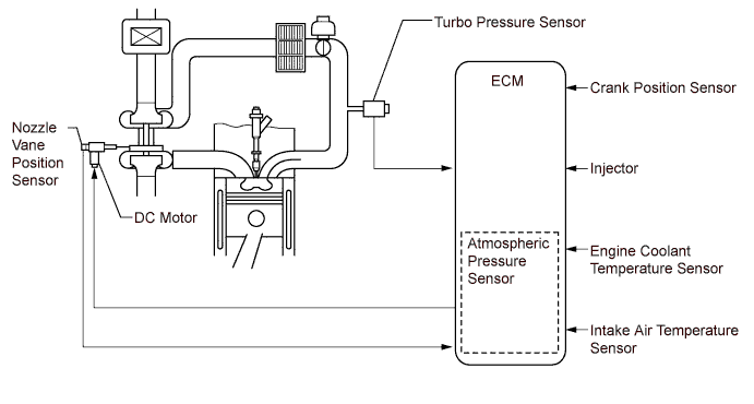
Turbocharger Control
-
The ECM calculates the optimal nozzle vane position in accordance with the driving conditions (engine speed, injection volume, atmospheric pressure, and engine coolant temperature etc.), and controls the nozzle vane position in accordance with this target nozzle vane position and the actual nozzle vane position signal provided by the nozzle vane position sensor.
-
-
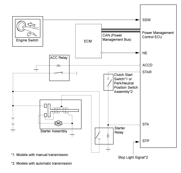
Starter Control (Models with Entry and Start System)
-
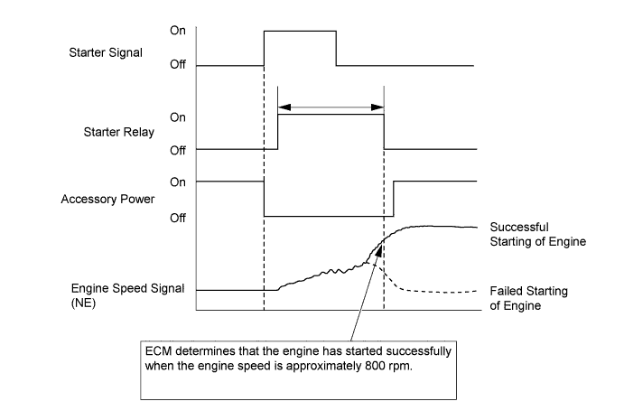
When the driver pushes the engine switch once and the power management control ECU detects a start signal, the power management control ECU will output ACCD and STAR signals and begin cranking. Also, the driver can continue cranking for up to 30 seconds by pushing and holding the engine switch.
-
If the engine speed reaches approximately 800 rpm, the ECM will judge that the engine has started and will send a signal to the power management control ECU using CAN communication. The power management control ECU will then stop the operation of the starter.
-
If CAN communication is cut between the power management control ECU and the ECM, the power management control ECU will receive an engine speed signal (NE) directly from the ECM and will stop the operation of the starter.
-
This system will cut off the power current which activates the accessories while the engine is being cranked. This prevents the intermittent blinking of the accessory lights caused by the voltage instability that occurs during engine cranking.
-
This system has the following protections:
-
The starter will not operate if the engine is operating normally.
-
If the engine switch is pushed and held, cranking will stop once the engine speed reaches a pre-determined level. This prevents the starter from over-revving.
-
If the engine does not start even after approximately 6 seconds of starter operation, the power management control ECU will cancel the starter relay output. Furthermore, if the engine does not start after the engine switch has been pushed and held and cranking has continued for 30 seconds, cranking will be canceled in order to protect the starter.
-
It will not be possible to operate the starter for 2 seconds after engine starting has failed and cranking has been canceled. This helps to protect the starter.
-
-
-
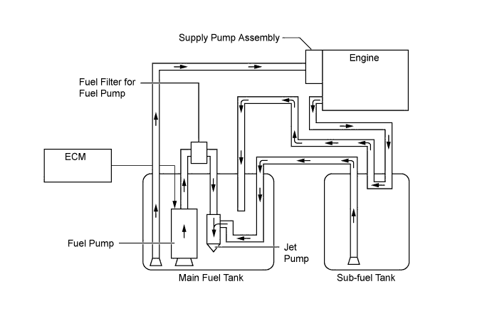
Fuel Pump Control (Models with Dual Fuel Tank)
-
The supply pump assembly delivers fuel from the main fuel tank to the engine. Therefore, fuel in sub fuel tank needs to be transferred to the main fuel tank. In this system, the ECM operates the fuel pump to transfer the fuel from the sub fuel tank to the main fuel tank using the jet pump built into the fuel pump.
-
-
Oil Maintenance Management System (Models for Europe)
-
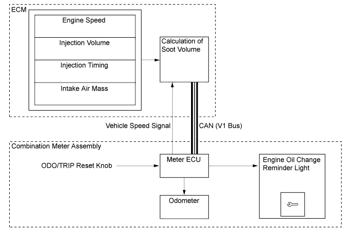
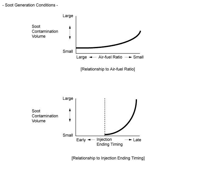
This system determines the deterioration of the engine oil and oil filter in accordance with the soot volume in the engine oil and oil filter. The engine ECU calculates the soot volume in the engine oil and oil filter in accordance with the vehicle speed, engine speed, injection timing, injection volume, and intake air mass. When the calculated value of the soot volume exceeds a predetermined value, the engine ECU will illuminate the engine oil change reminder light. Thus, this system informs the driver that the engine oil and the oil filter must be changed.
-
In addition to controlling the illumination of the engine oil change reminder light by counting the soot volume, the engine ECU illuminates the engine oil change reminder light when the vehicle's driven distance reaches 30000 km. Thus, this function enhances the reliability of the system.
Tech Tips
This system does not determine the deterioration of the engine oil based on the elapsed time. Even if the engine oil change reminder light does not illuminate, the engine oil and oil filter should be changed at 2-year intervals at the maximum.
-
-
Engine Mount Control
-
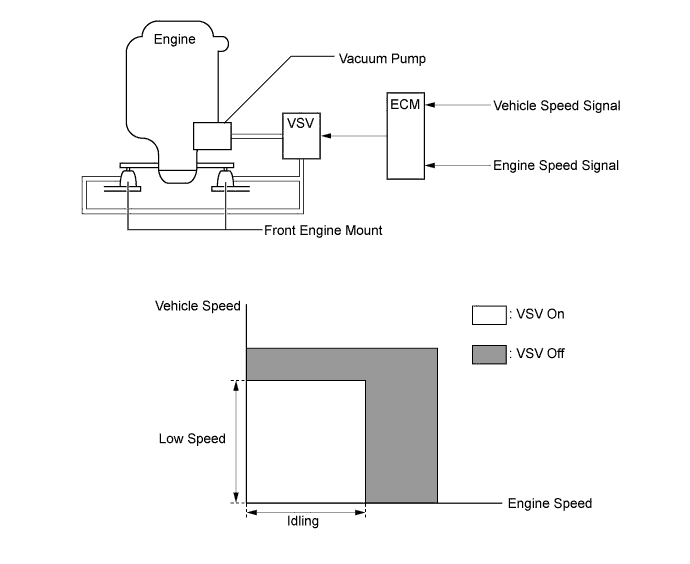
The ECM determines the idling state of the engine and the low speed state of the vehicle in accordance with the engine speed and the vehicle speed. Thus, the ECM controls the introduction of vacuum from the vacuum pump (for the engine) to the engine mount by turning the VSV on or off.
-
A hysteresis is provided for both the engine speed and the vehicle speed at the point in which the VSV switches from on to off.
-
While the engine is cranking, the VSV is off.
-
When the ECM determines that the engine speed is anything other than idle in accordance with the engine speed and the vehicle speed, it stops the introduction of vacuum into the engine mount by turning the VSV off.
-
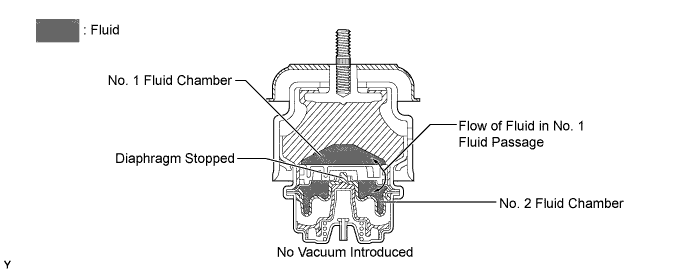
When no vacuum is introduced into the engine mount, the diaphragm does not move, so the No. 1 fluid passage remains closed. In this state, the fluid passes only through the No. 1 fluid passage in order to flow back and forth between the No. 1 and No. 2 fluid chambers.
-
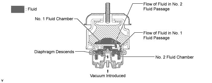
When the ECM determines via the engine speed and the vehicle speed that the engine is idling, it turns the VSV on to introduce vacuum into the engine mount.
-
When a vacuum is introduced into the engine mount, it pulls the diaphragm down, causing the No. 2 fluid passage to open. As a result, a large volume of fluid flows back and forth between the No. 1 and No. 2 fluid chambers, thus minimizing the fluid resistance and softening the engine mount characteristics.
-
-
Power Heater Control (Cold Area Specification Models)
-
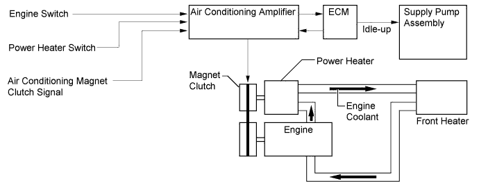
Pressing the power heater switch provided in the instrument panel engages the magnetic clutch, causing the rotor in the power heater to rotate and the silicon oil to mix. The sheer heat that is thus generated heats the engine coolant.
-
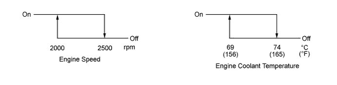
The power heater is controlled in accordance with engine speed and engine coolant temperature as described below. While the power heater is engaged, the engine idling speed increases up to 1200 rpm (AT) or up to 1300 rpm (MT).
-
However, the power heater is turned off when the engine is cranking or the vehicle is accelerating (for 5 seconds while the vehicle speed is under 30 km/h (19 mph) and the throttle opening angle is more than 45%).
-
-
Oil Pressure Control System (Models Compliant with EURO 5+ Emission Regulations)
-
The ECM controls the oil pressure switching valve of the electric variable oil pressure type oil pump in accordance with engine coolant temperature, engine speed, and fuel injection volume to regulate the engine oil pressure in 2 stages.
-
When the ECM turns the oil pressure switching valve off, no oil pressure is applied to the lower portion of the sleeve valve. The oil pressure of the oil pump pushes the sleeve valve downward while compressing the relief valve spring together with the relief valve. Consequently, the oil passage provided on the side of the sleeve valve is moved downward as well. As a result, the opening pressure of the relief valve increases and the engine oil pressure is controlled to a high level.
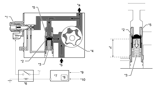
Text in Illustration *1 Oil Pressure Switching Valve *2 Relief Valve *3 Relief Valve Spring *4 Oil Pump *5 Sleeve Valve *6 Oil Pressure Relay *7 ECM *8 Fuel Injection Volume *9 Engine Coolant Temperature Sensor *10 Crank Position Sensor *a To Engine Parts *b From Oil Pan *c Relief Valve Spring Length: Short - - Engine Oil Oil Pressure Necessary to Push Down Relief Valve: High -
When the ECM turns the oil pressure switching valve on, oil pressure is applied to the lower portion of the sleeve valve. This pushes the sleeve valve upward and moves the oil passage provided on the side of the sleeve valve upward also. At the same time, the relief valve is moved upward by the force of the relief valve spring. As a result, the opening pressure of the relief valve decreases and the engine oil pressure is controlled to a low level.
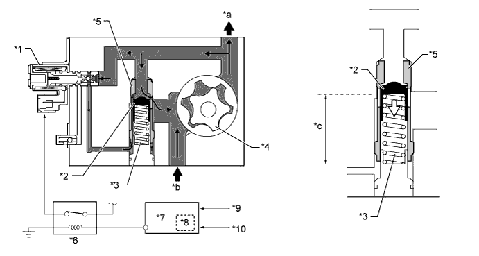
Text in Illustration *1 Oil Pressure Switching Valve *2 Relief Valve *3 Relief Valve Spring *4 Oil Pump *5 Sleeve Valve *6 Oil Pressure Relay *7 ECM *8 Fuel Injection Volume *9 Engine Coolant Temperature Sensor *10 Crank Position Sensor *a To Engine Parts *b From Oil Pan *c Relief Valve Spring Length: Long - - Engine Oil Oil Pressure Necessary to Push Down Relief Valve: Low
-
-