FUEL SYSTEM DETAILS
-
SYSTEM CONTROL
-
Common-rail System
-
In this system, the high pressurized fuel supplied by the supply pump is stored in the common-rail, and the ECM sends signals to the injectors via the injector driver in order to control the injection timing and injection volume.
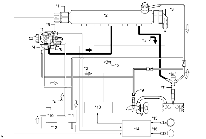
Text in Illustration (Model Compliant with EURO 5+ Emission Regulations:) *1 Fuel Pressure Sensor *2 Common-rail Assembly *3 Pressure Discharge Valve *4 Supply Pump Assembly *5 Fuel Temperature Sensor *6 Suction Control Valve (SCV) *7 Injector Assembly *8 Turbocharger Sub-assembly *9 Exhaust Fuel Addition Injector Assembly *10 Fuel Filter Assembly *11 Fuel Cooler *12 Fuel Tank *13 Injector Driver *14 ECM *15 Crank Position Sensor (NE Signal) *16 Camshaft Position Sensor (G Signal) *a Fuel (Suction) *b Fuel (Return) *c Fuel (High Pressure) *d Fuel (To Exhaust Fuel Addition Injector Assembly) 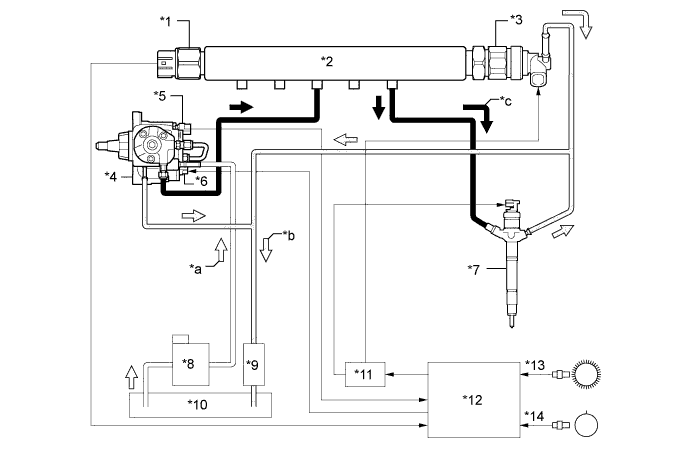
Text in Illustration (Except Model Compliant with EURO 5+ Emission Regulations:) *1 Fuel Pressure Sensor *2 Common-rail Assembly *3 Pressure Discharge Valve *4 Supply Pump Assembly *5 Fuel Temperature Sensor *6 Suction Control Valve (SCV) *7 Injector Assembly *8 Fuel Filter Assembly *9 Fuel Cooler *10 Fuel Tank *11 Injector Driver *12 ECM *13 Crank Position Sensor (NE Signal) *14 Camshaft Position Sensor (G Signal) *a Fuel (Suction) *b Fuel (Return) *c Fuel (High Pressure) - -
-
-
-
CONSTRUCTION
-
Supply Pump Assembly
-
An HP3 type supply pump is used.
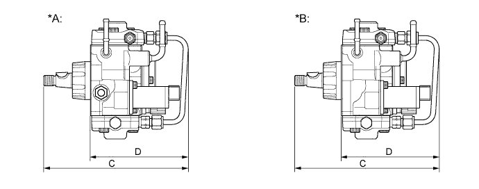
Text in Illustration *A Models Compliant with EURO 5+ Emission Regulations *B Except Models Compliant with EURO 5+ Emission Regulations Supply Pump Specifications Type HP3 Length C 190.2 mm (7.49 in.) D 129.0 mm (5.08 in.) SCV 1 Plunger φ 8.5 mm x 2 Weight 3800 g (8.38 lb.) Tech Tips
-
The ECM learns and memorizes the pump discharge volume variances associated with the individual differences in the supply pumps. Therefore, make sure to perform the operation described below after replacing the supply pump. For details, refer to the corresponding Repair Manual for this model.
-
Connect an intelligent tester II to the DLC3 connector and use the tester to reset the learned value. Alternatively, connect the SST (09843-18040) between the TC and CG terminals of the DLC3 connector, and leave the engine switch on (IG) for approximately 3 minutes to reset the learned value.
-
After resetting, start the engine, allow it to idle* for approximately 1 minute, and turn the engine switch off to enable the engine to memorize the learned value.
-
*: The engine coolant temperature should be 60°C (140°F) or more, and the fuel temperature should be 20°C (68°F) or more.
-
-
The supply pump consists of an eccentric camshaft, a ring cam, two plungers, four check valves, a Suction Control Valve (SCV), a fuel temperature sensor, and a feed pump.
-
The two plungers are placed opposite each other outside of the ring cam.
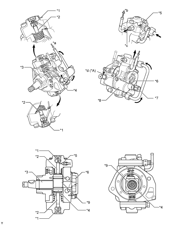
Text in Illustration *A Models Compliant with EURO 5+ Emission Regulations - - *1 Check Valve (for Suction) *2 Plunger *3 Eccentric Camshaft *4 Ring Cam *5 Check Valve (for Discharge) *6 Feed Pump *7 Fuel Temperature Sensor *8 SCV *9 Eccentric Cam Portion - - *a From Fuel Tank (for Suction) *b To Fuel Tank (for Return) *c To Common-rail *d To Exhaust Fuel Addition Injector Assembly
-
-
Common-rail Assembly
-
The function of the common-rail is to store the fuel that has been pressurized by the supply pump.
-
The common-rail is provided with a fuel pressure sensor and pressure discharge valve.
-
The fuel pressure sensor detects the fuel pressure in the common-rail.
-
The pressure discharge valve regulates the fuel pressure. In the pressure discharge valve, the plunger opens and closes in accordance with the actuation signals from the injector driver. Thus, it regulates pressure by releasing excess pressure from the common-rail. In addition, it has a pressure reduction function in case of emergency.
-
Internally, the common-rail contains a main hole and five branch holes that intersect the main hole. Each branch hole functions as an orifice that dampens the fluctuation of the fuel pressure.
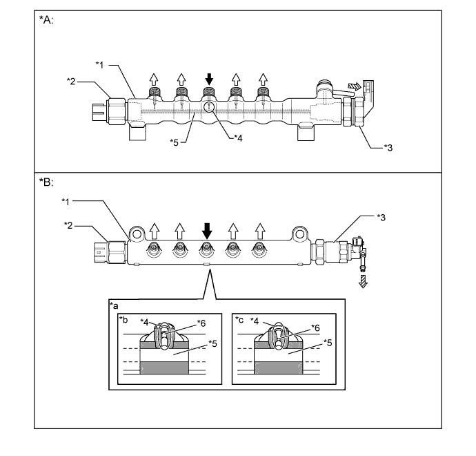
Text in Illustration *A Models Compliant with EURO 5+ Emission Regulations *B Except Models Compliant with EURO 5+ Emission Regulations *1 Common-rail Assembly *2 Fuel Pressure Sensor *3 Pressure Discharge Valve *4 Branch Hole *5 Main Hole *6 Orifice *a Common-rail Cross Section *b Fuel Inlet *c Fuel Outlet - - 
From Supply Pump 
To Injector Assembly 
To Fuel Tank (Excess Pressure) - - Tech Tips
-
The fuel pressure sensor has its sealing portion plastic-deformed in order to keep sealing performance, so do not reuse it after disassembling.
-
If parts that affect the alignment have been changed, make sure to replace the pipe with a new one as well. The parts that require the replacement of a pipe are listed below:
-
Injection pipe: injector, common-rail, and cylinder head
-
Fuel inlet pipe: supply pump, common-rail, cylinder block and cylinder head
-
For details, refer to the corresponding Repair Manual for this model.
-
-
-
Injector Assembly
-
Except on the models compliant with EURO 5+ emission regulations, each injector assembly consists of a nozzle needle, a piston, and a solenoid valve.
-
On the models compliant with EURO 5+ emission regulations, each injector assembly consists of a nozzle needle, 2 pistons, a three-way valve and a piezo actuator.
-
An injector compensation value and a Quick Response (QR) code containing encoded characteristics of the injector are printed on each injector.
-
The injector compensation value and QR code contain various pieces of information regarding the injector, such as model code and injection volume correction.
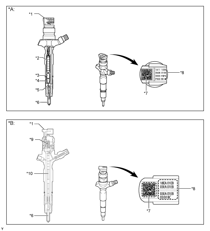
Text in Illustration *A Models Compliant with EURO 5+ Emission Regulations *B Except Models Compliant with EURO 5+ Emission Regulations *1 Injector Assembly *2 Piezo Actuator *3 No. 1 Piston *4 No. 2 Piston *5 Three-way Valve *6 Nozzle Needle *7 QR Code *8 Injector Compensation Value *9 Solenoid Valve *10 Piston Tech Tips
-
If the ECM is replaced, use the intelligent tester II and input the injector compensation values of all 4 injectors. If the injector is replaced, input the injector compensation value of the replaced injector. Then, the proper compensation will be made so that the injection volume precision prior to the replacement will remain unchanged. For details, refer to the corresponding Repair Manual for this model.
-
The QR code, which requires a special scan tool, is not used at TOYOTA dealers.
-
What is Quick Response (QR) Code?
-
QR code, a matrix symbology consisting of an array of nominally square cells, allows omni-directional, high-speed reading of large amounts of data.
-
QR code encodes many types of date such as numeric, alphanumeric, kanji, kana and binary code. A maximum of 7089 characters (numeric) can be encoded.
-
QR code (2D code) contains information in the vertical and horizontal directions, whereas a bar code contains data in one direction only. QR code (2D code) holds a considerably greater volume of information than a bar code.
-
-
-
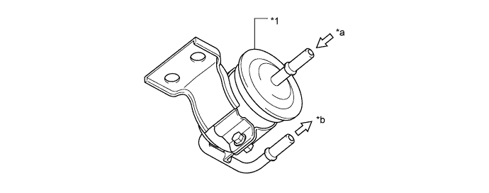
Fuel Filter Assembly
-
The cartridge type fuel filter is used.
-
Except on the models for Europe, a fuel filter warning switch is provided in the fuel filter.
-
On the models for Europe, in order to improve the fuel heating performance, a fuel heater is used.
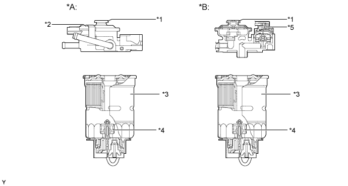
Text in Illustration *A Except Models for Europe *B Models for Europe *1 Priming Pump *2 Fuel Filter Warning Switch *3 Filter Cartridge *4 Fuel Sedimenter Level Warning Switch *5 Fuel Heater Assembly - -
-
-
Fuel Tank
-
On the 5-door models with a spare tire installed on the back door, a dual fuel tank is used.
-
On the 5-door models with a spare tire installed on the under floor or 3-door models, a single fuel tank is used.
-
On the 5-door models with single fuel tank, a multiplex layered plastic fuel tank is used.
-
On the models with dual fuel tank, a multiplex layered main fuel tank is used.
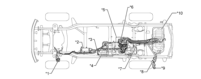
Text in Illustration (5-door Models with Dual Fuel Tank:) *1 Fuel Filter Assembly *2 Fuel Cooler *3 Main Tube *4 Main Fuel Tank (Made of Multiplex Layer Plastic) *5 Return Tube *6 Fuel Pump Filter Assembly *7 Fuel Filler Hose *8 Fuel Filler Pipe *9 Fuel Tank Cap *10 Sub Fuel Tank (Made of Steel) 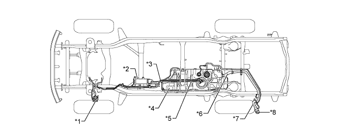
Text in Illustration (5-door Models with Single Fuel Tank:) *1 Fuel Filter Assembly *2 Fuel Cooler *3 Main Tube *4 Fuel Tank (Made of Multiplex Layer Plastic) *5 Return Tube *6 Fuel Filler Hose *7 Fuel Filler Pipe *8 Fuel Tank Cap 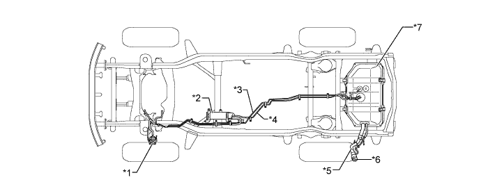
Text in Illustration (3-door Models:) *1 Fuel Filter Assembly *2 Fuel Cooler *3 Main Tube *4 Return Tube *5 Fuel Filler Pipe *6 Fuel Tank Cap *7 Fuel Tank (Made of Steel) - - -
The multiplex layered plastic fuel tank consists of 6 layers of 4 types of materials.
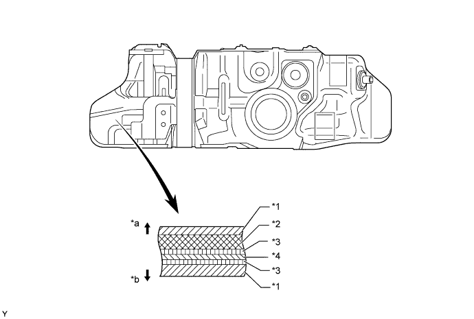
Text in Illustration *1 High Density Polyethylene (HDPE) *2 Regrind Material *3 Adhesive *4 Ethylene Vinyl Alcohol Copolymer (EVOH) *a Fuel Tank Outside *b Fuel Tank Inside -
On the models with dual fuel tank, a fuel pump and jet pump are provided in the main fuel tank to transfer the fuel from sub fuel tank to main fuel tank. This is accomplished by utilizing the fuel flow through the jet pump. The pressure difference is created by the fuel as it passes through the venturi, and it is used to suck the fuel out of the sub fuel tank and send it to the main fuel tank.
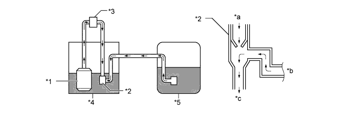
Text in Illustration *1 Fuel Pump *2 Jet Pump *3 Fuel Pump Filter Assembly *4 Main Fuel Tank *5 Sub Fuel Tank - - *a From Fuel Pump *b From Sub Fuel Tank *c To Main Fuel Tank - -
-
-
Fuel Pump Filter Assembly
-
On the models with dual fuel tank, a fuel pump filter assembly is provided between the jet pump and fuel pump.
Text in Illustration *1 Fuel Pump Filter Assembly - - *a From Fuel Pump *b To Jet Pump
-
-
Fuel Cooler
-
An air-cooled fuel cooler is used, along with the increased power output of the engine.
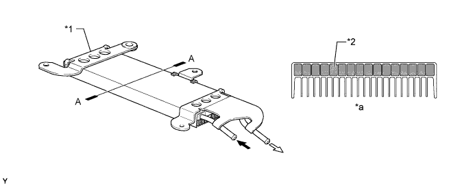
Text in Illustration *1 Fuel Cooler *2 Fuel *a A - A Cross Section - - To Fuel Tank From Engine
-
-
-
OPERATION
-
Supply Pump Assembly
-
Due to the rotation of the eccentric cam, the ring cam pushes plunger "A" upward as illustrated below. The force of the spring pulls plunger "B" (which is located opposite plunger "A") upward. As a result, plunger "B" draws fuel in, and plunger "A" pumps fuel at the same time.
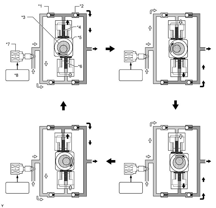
Text in Illustration *1 Check Valve (for Suction) *2 Check Valve (for Discharge) *3 Eccentric Cam *4 Plunger "A" *5 Ring Cam *6 Plunger "B" *7 Section Control Valve (SCV) *8 ECM -
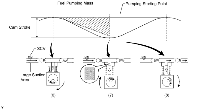
The ECM controls the opening of the SCV in order to regulate the volume of fuel that is pumped by the supply pump to the common-rail. Consequently, the fuel pressure in the common-rail is controlled to the target injection pressure.
-
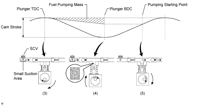
When the opening of the SCV is small, the fuel suction area is kept small, which decreases the transferable fuel quantity.
-
When the plunger strokes fully, however, the suction volume becomes small due to the small suction area.
-
Pumping will start when the fuel pressure has become higher than the common-rail pressure.
-
When the opening of the SCV is large, the fuel suction area is kept large, which increases the transferable fuel quantity.
-
If the plunger strokes fully, the suction volume will increase because the suction area is large.
-
Pumping will start at the time when the fuel pressure has become higher than the common-rail pressure.
-
-
Injector Assembly (Models Compliant with EURO 5+ Emission Regulations)
-
When current is applied to the piezo actuator, the No. 1 piston, No. 2 piston and three-way valve are pushed down.
-
The orifice on the upper part of the three-way valve opens and the fuel in the control chamber flows out.
-
The fuel pressure in the control chamber drops.
-
As a result, the nozzle needle is pushed up due to fuel pressure, causing fuel injection.
-
Current to the piezo actuator is shut off and the No. 1 and No. 2 pistons and the three-way valve are pushed up due to spring tension.
-
The orifice on the upper part of the three-way valve closes to stop fuel flow.
-
The fuel pressure in the control chamber rises.
-
As a result, the nozzle needle goes down to stop fuel injection.
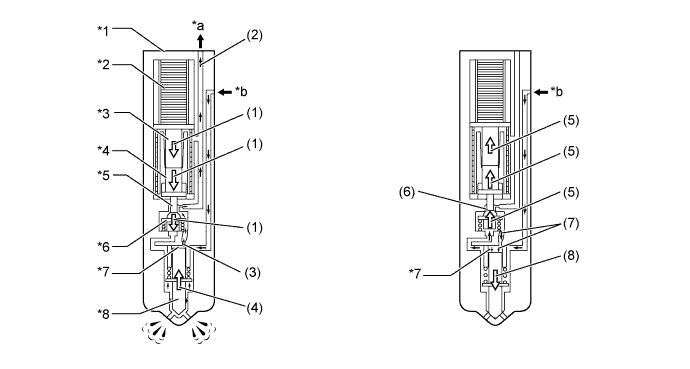
Text in Illustration *1 Injector Assembly *2 Piezo Actuator *3 No. 1 Piston *4 No. 2 Piston *5 Orifice *6 Three-way Valve *7 Control Chamber *8 Nozzle Needle *a Return Fuel *b Fuel from Common-rail
-
-
Injector Assembly (Except Models Compliant with EURO 5+ Emission Regulations)
-
When electrical current is applied to the solenoid coil, it pulls the solenoid valve up.
-
The orifice of the control chamber opens, allowing the fuel to flow out.
-
The fuel pressure in the control chamber drops.
-
Simultaneously, fuel flows from the orifice to the bottom of the piston and raises the piston up (to enhance response).
-
As a result, the piston raises the nozzle needle to inject fuel.
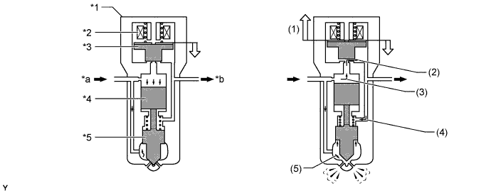
Text in Illustration *1 Injector Assembly *2 Solenoid Coil *3 Solenoid Valve *4 Piston *5 Nozzle Needle - - *a Fuel from Common-rail *b Return Fuel
-
-
Fuel Filter Assembly
-
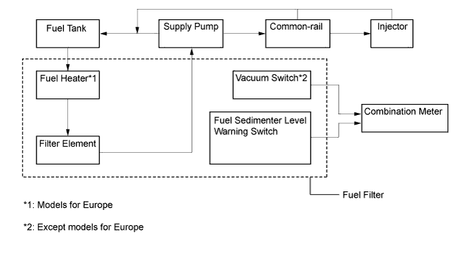
Except on the models for Europe, a fuel filter warning switch is used.
-
On the models for Europe, a fuel heater is used.
-
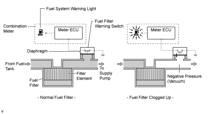
A fuel filter warning switch, which turns on or off when the internal vacuum of the filter increases, is provided in the fuel filter. This switch, which turns off when the internal vacuum of the fuel filter increases to a predetermined level, is connected by wire to the meter ECU.
-
When the meter ECU detects that the internal vacuum of the fuel filter has increased (by way of the fuel filter warning switch off signal), it determines that the fuel filter has become clogged. Then, it illuminates the fuel system warning light on the combination meter to urge the driver to replace the fuel filter.
-
The fuel heater electrically heats the fuel.
-
When the water in the sedimenter section reaches a certain amount, the fuel sedimenter level warning switch comes on, the warning light in the combination meter illuminates, and the multi buzzer sounds.
-
-