LIGHTING SYSTEM DETAILS
-
FUNCTION OF MAIN COMPONENTS
-
Daytime Running Light System
Component Function Main Body ECU (Driver Side Junction Block Assembly) The main body ECU (driver side junction block assembly) receives various signals and illuminates the high beams. Engine Room Junction Block Power Distributor The power distributor dims the high beams using duty control. ECM The ECM outputs an engine speed signal and transmits it to the main body ECU (driver side junction block assembly). Headlight Dimmer Switch Assembly Light Control Switch The light control switch outputs a light control signal and transmits it to the main body ECU (driver side junction block assembly). Parking Brake Switch Assembly The parking brake switch assembly outputs a parking brake operation signal to the main body ECU (driver side junction block assembly). -
High Intensity Discharge (HID) Headlight System
Component Function Headlight Dimmer Switch Assembly The headlight dimmer switch assembly transmits a HEAD position signal to the main body ECU (driver side junction block assembly). Main Body ECU (Driver Side Junction Block Assembly) The main body ECU (driver side junction block assembly) receives the HEAD position signal and transmits a signal to the light control ECU. Headlight Assembly Discharge Bulb The discharge bulb light shines ahead over a broader area and further forward, increasing the area visible to the driver. Light Control ECU The light control ECU transforms battery voltage to a high voltage of up to 20000 V and applies it to the discharge bulbs in order to illuminate them. Combination Meter Assembly Taillight Indicator Light The taillight indicator lights up to inform the driver when the taillights turn on. Engine Room Junction Block H-LP Relays The relay supplies power to the light control ECU. -
Automatic High Beam System
Component Function Inner Rear View Mirror Assembly Automatic High Beam Sensor The automatic high beam sensor determines when to turn the high beams on and off after identifying the lights of oncoming vehicles, preceding vehicles and other lights from the picture information of its camera sensor. Then, it sends high beam request signals to the AFS ECU (headlight swivel ECU assembly) via Local Interconnect Network (LIN). AFS ECU (Headlight Swivel ECU Assembly)
-
The AFS ECU (headlight swivel ECU assembly) receives high beam illumination request signals from the main body ECU (driver side junction block assembly).
-
The AFS ECU (headlight swivel ECU assembly) uses a LIN communication (for automatic high beam actuation).
-
The AFS ECU (headlight swivel ECU assembly) acts as the gateway between the automatic high beam sensor and CAN (No. 2 bus).
Tech Tips
Even though the vehicle is not equipped with AFS, an AFS ECU (headlight swivel ECU assembly) is provided to control the automatic high beam system.
Power Management Control ECU The power management control ECU performs the gateway function between the CAN No. 1 bus and CAN No. 2 bus. Main Body ECU (Driver Side Junction Block Assembly)
-
The main body ECU (driver side junction block assembly) receives AUTO position signals and high beam position the signal of headlight dimmer switch assembly.
-
The main body ECU (driver side junction block assembly) receives high beam request signals from the inner rear view mirror assembly and transmits a duty control value to the power distributor.
Skid Control ECU The skid control ECU outputs information about the speed of the front right wheel. This information is used by the automatic high beam sensor to control switching between the high and low beams of the automatic high beam system. ECM The ECM outputs a signal to indicate that the shift lever is in R. Based on this signal, the automatic high beam sensor determines the direction of vehicle movement. Headlight Dimmer Switch Assembly The headlight dimmer switch assembly transmits AUTO position signals to the main body ECU (driver side junction block assembly). Steering Angle Sensor The steering angle sensor outputs the steering angle. Combination Meter Assembly Automatic High Beam Indicator Light
-
The automatic high beam indicator light flashes to inform the driver when the AFS ECU (headlight swivel ECU assembly) detects a malfunction is in this system.
-
The automatic high beam indicator light illuminates to inform the driver when the automatic high beam system is activated.
Headlight High Beam Indicator Light The headlight high beam indicator light illuminates to inform the driver when the high beams are on. Engine Room Junction Block (Power Distributor) HEAD Relay The HEAD relay is a semiconductor type relay that performs duty control for the high beam bulbs based on request signals that are received from the main body ECU (driver side junction block assembly). Automatic Light Control Sensor The automatic light control sensor detects the ambient light level and transmits to the main body ECU (driver side junction block assembly). -
-
Automatic Headlight Beam Level Control System
Component Function Headlight Dimmer Switch Assembly The headlight dimmer switch assembly transmits a HEAD position signal to the main body ECU (driver side junction block assembly). Main Body ECU (Driver Side Junction Block Assembly) The main body ECU (driver side junction block assembly) receives a HEAD position signal. Headlight Leveling ECU Assembly
-
The headlight leveling ECU assembly detects changes of vehicle movement based on the rear height control sensor, front RH wheel speed sensor and engine speed signals.
-
The headlight leveling ECU outputs control signals to the headlight leveling motors based on the detected value.
-
This ECU provides initial set control and a fail-safe function.
Headlight Assembly Headlight Leveling Motor
-
Based on the signals received from headlight leveling ECU assembly, each actuator moves the low beam reflector in the headlight to vary its angle.
-
The headlight leveling motor uses a stepper motor to precisely regulate the angle of the reflector.
Rear Height Control Sensor Sub-assembly RH The rear height control sensor sub-assembly RH detects vehicle movement and transmits a signal to the headlight leveling ECU assembly. Combination Meter Assembly Headlight Leveling Indicator Light The headlight leveling indicator light flashes to inform the driver when the headlight leveling ECU assembly detects a malfunction in this system. Engine Room Junction Block H-LP Relays The H-LP relay supplies power to the low beams. -
-
Automatic Light Control System
Component Function Main Body ECU (Driver Side Junction Block Assembly) The main body ECU (driver side junction block assembly) receives various signals and illuminates the headlights, taillights and license plate lights. Engine Room Junction Block Power Distributor The power distributor supplies power to the front exterior lights. Automatic Light Control Sensor The automatic light control sensor detects the ambient light level. Headlight Dimmer Switch Assembly Light Control Switch The light control switch transmits an AUTO position signal to the main body ECU (driver side junction block assembly). Combination Meter Assembly Taillight Indicator Light The taillight indicator lights up to inform the driver when the taillights turn on. -
Light Automatic Turn-off System
Component Function Main Body ECU (Driver Side Junction Block Assembly) The main body ECU (driver side junction block assembly) receives various signals, and turns off the exterior lights. Engine Room Junction Block Power Distributor The power distributor shuts down the power source to the front exterior lights. Headlight Dimmer Switch Assembly Light Control Switch The light control switch transmits a light control switch position signal to the main body ECU (driver side junction block assembly). Door Lock Assembly Front LH/RH, Rear LH/RH The door lock assembly detects the whether a door is locked or unlocked and transmits a signal to the main body ECU (driver side junction block assembly). Door Control Receiver*1 The door control receiver receives the ID code from the door control transmitter and transmits it to the main body ECU (driver side junction block assembly). Door Control Receiver*2 The door control receiver receives the ID code from the door control transmitter in the actuation area and transmits it to the main body ECU (driver side junction block assembly). Certification ECU (Smart Key ECU Assembly)*2 The certification ECU (smart key ECU assembly) judges and certifies the ID code from the door control receiver.
-
*1: Models without smart entry and start system
-
*2: Models with smart entry and start system
-
-
Door Mirror Foot Light System
Component Function Main Body ECU (Driver Side Junction Block Assembly) The main body ECU (driver side junction block assembly) receives various signals and illuminates the door mirror foot lights. Outer Mirror Control ECU Assembly LH/RH* The outer mirror control ECU receives request signals and illuminates the door mirror foot lights. Door Lock Switch Driver, Front Passenger The door lock switch outputs the lock/unlock signal to the main body ECU (driver side junction block assembly) or the power window regulator master switch assembly. Power Window Regulator Master Switch Assembly The power window regulator master switch assembly receives the door lock/unlock signal from the driver side door lock switch and transmits it to the main body ECU (driver side junction block assembly). Certification ECU (Smart Key ECU Assembly) The certification ECU (smart key ECU assembly) judges and certifies the ID code. ECM The ECM receives the shift position signals from the park/neutral position switch and transmits them to the main body ECU (driver side junction block assembly). Door Lock Detection Switch Front LH/RH, Rear LH/RH The door lock detection switch detects whether a door is locked or unlocked and transmits a signal to the main body ECU (driver side junction block assembly). *: Models with memory function
-
-
OPERATING CONDITION
-
Daytime Running Light System
-
The daytime running lights illuminate when the following conditions are met.
-
The ignition switch is ON.
-
An engine speed signal is input (engine is running).
-
The low beams are not on.
-
The parking brake is off.
-
-
-
Automatic High Beam System
-
The automatic high beam system will operate as follows:
Condition Details Active When all of the following conditions are met, the automatic high beam system is activated and the automatic high beam indicator light turns on:
-
The ignition switch is ON.
-
The headlight dimmer switch is in the AUTO position and high beam position.
-
The automatic light control sensor outputs the night mode signal (to turn the headlights on).
High Beam on When all of the following conditions are met, the automatic high beam system turns on the high beams after a short delay:
-
Vehicle speed is more than approximately 20 mph (32 km/h).
-
The area in front of the vehicle is dark.
-
No oncoming vehicles are present with the headlights on.
-
No preceding vehicles are present with the taillights on.
-
Few streetlights are present along the street ahead.
High Beam off When any of the following conditions are met, the automatic system turns off the high beams after a short delay:
-
Vehicle speed is less than approximately 20 mph (32 km/h).
-
The area in front of the vehicle is not dark.
-
An oncoming vehicle with headlights on is detected.
-
A preceding vehicle with taillights on is detected.
-
Several streetlights are present along the street ahead.
-
-
-
Door Mirror Foot Light System
-
The door mirror foot light system operates as follows:
Function Operation Condition Actuation Area-linked* When all of the following conditions are met, the door mirror foot lights automatically turn on:
-
The ignition switch is off.
-
All doors are closed.
-
The key is detected in the actuation area.
When the following condition is met, the door mirror foot lights automatically turn off:
The key is not detected in the actuation area.
Door Unlock-linked When all of the following conditions are met, the door mirror foot lights automatically turn on:
-
The ignition switch is off.
-
All doors are closed.
-
Any door is unlocked when all doors are locked.
Door Lock-linked When either of the following conditions is met, the door mirror foot lights automatically turn off:
-
All doors are locked when all doors are closed and any door is unlocked.
-
All doors are locked again when all doors are closed and locked with the lights on.
Door-linked When the following condition is met, the door mirror foot lights automatically turn on:
Any door is opened and then closed.
Delay When approximately 15 seconds elapse after one of the following conditions is met, the door mirror foot lights turn off:
-
An actuation area-linked function is used.*
-
The door unlock-linked is active.
-
Any door is opened and then closed.
Shift Position-linked When all of the following conditions are met, the door mirror foot lights automatically turn off:
-
The ignition switch is ON.
-
The shift lever is moved from P.
*: Models with smart entry and start system
-
-
-
-
FUNCTION
-
Automatic High Beam System
-
When passing an oncoming vehicle:
-
The automatic high beam system turns off the high beams before an oncoming vehicle comes within approximately 800 m (2625 ft).
-
When an oncoming vehicle passed camera sensor range, the automatic high beam system turns the high beams on after a short delay.
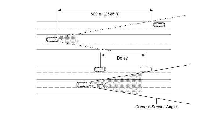
Tech Tips
-
The detection distance varies depending on detected objects.
-
The timing of turning on and off the high beams varies depending on the intensity of oncoming (and preceding) vehicle lights.
-
-
When passing a preceding vehicle:
-
When approaching a preceding vehicle, the automatic high beam system turns off the high beams approximately 600 m (1969 ft) before reaching it.
-
When a preceding vehicle past camera sensor range, the automatic high beam system turns the high beams on after a short delay.
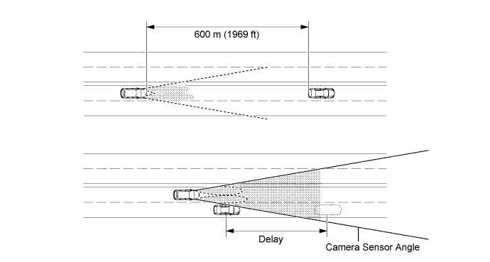
Tech Tips
The timing of turning on and off the high beams varies depending on the intensity of the preceding vehicle's lights.
-
-
-
Automatic Headlight Beam Level Control System
-
The automatic headlight beam level control system mainly consists of the headlight leveling ECU assembly, rear height control sensor assembly and 2 headlight leveling motors. The headlight leveling ECU assembly controls the system.
-
The ECU detects the movement of the suspension from the rear height control sensor sub-assembly RH and the vehicle speed from the front RH speed sensor.
-
The ECU then controls the headlight leveling motor based on this information, in order to change the headlight reflector angle.
-
When the headlight leveling ECU assembly detects a vehicle speed of 1 km/h (0.6 mph) and the ignition switch is turned to ON, the ECU executes the initial setting of the stepper motors.
-
-
Light Automatic Turn-off System
-
This system has the following functions:
Function Outline Headlight and Taillight Turn-off Function When 30 seconds elapse after all of the following conditions are met, the exterior lights turn off:
-
The ignition switch is turned from ACC, or ON to off.
-
The driver door is opened and then closed.
-
The light control switch is in the HEAD or AUTO position.
-
All doors are closed.
Taillight Turn-off Function When all of the following conditions are met, the exterior lights turn off:
-
The ignition switch is turned from ACC, or ON to off.
-
The driver door is opened.
-
The light control switch is in tail position.
-
-
-
-
CONSTRUCTION
-
HID Headlight Light System
-
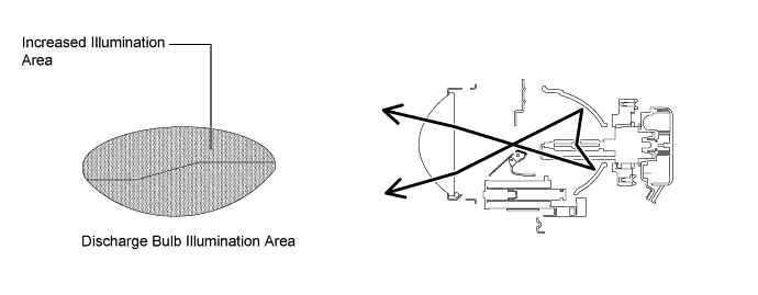
Discharge Bulb
Instead of the filament contained in an incandescent bulb, a discharge bulb contains an arc tube, which is filled with xenon gas and metal halide.

-
Bi-function Mechanism
-
The bi-function mechanism consists of a headlight solenoid, link and shade.
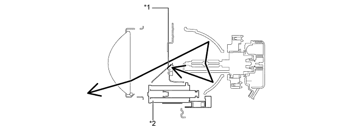
Text in Illustration *1 Shade *2 Headlight Solenoid
-
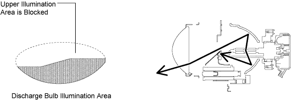
If the low beam is selected, the upper illumination area of the discharge bulb will be blocked by a shade and only the lower illumination area will be used.
-
If the high beam is selected, the headlight solenoid will slide the shade down to allow use of the upper illumination area, thus increasing the illumination area and improving visibility when the high beam is selected.
-
-
-
Automatic High Beam System
-
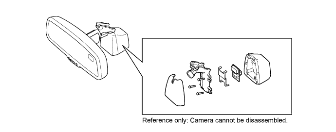
Inner Rear View Mirror Assembly (Automatic High Beam Sensor)
The inner rear view mirror assembly consists of the Complementary Metal Oxide Semiconductor (CMOS) camera that receives images and the mirror portion that identifies light sources, and judges whether to turn high beams on or off.
-
-
-
FAIL-SAFE
-
HID Headlight System
-
The light control ECU executes the fail-safe actions listed below in accordance with the problem that has been detected.
Problem Outline Abnormal Input Voltage If the voltage that is input to the light control ECU deviates from the normal operating voltage (9 to 16 V), the light control ECU stops illuminating the headlights. It resumes illuminating the headlights once the voltage reverts to the normal operating voltage. However, if the input voltage decreases after the headlights have illuminated, the headlights will remain illuminated until the input voltage becomes insufficient to light the bulbs. Abnormal Output (Open Circuit or Short Circuit) or Flashing Bulb If an abnormal condition (open or short) occurs in the voltage that is output by the light control ECU, or if the bulb flashes, the light control ECU stops illuminating the headlights and will maintain this state until the power is reinstated. Power is reinstated by turning the headlight control switch from off to on. Bulb Open Circuit If a bulb is not inserted in its socket, the light control ECU stops generating high voltage until the bulb is inserted correctly and the power is reinstated. Power is reinstated by turning the headlight control switch from off to on or turning the ignition switch from off to ON.
-
-
Automatic Headlight Beam Level Control System
-
If the headlight leveling ECU assembly detects a malfunction in the automatic headlight beam level control system, it will take the actions indicated in the table below.
Trouble Area System Operation Headlight Leveling Indicator Light Headlight Leveling ECU Assembly Stops at current condition. - Speed Sensor Signal Continues control only when the vehicle is stopped. Flash Rear Height Control Sensor Sub-assembly Signal
-
Stops control after returning to initial position (If failure occurs at higher than initial position).
-
Stops control at current condition (If failure occurs at lower than initial position).
Flash Steering Angle Sensor Signal Continues control until a position of 0.7° less than the current position is reached, and resumes normal control after returning to the initial position. Flash Headlight Level Motor
-
Stops control after returning to initial position (If failure occurs at higher than initial position).
-
Stops control at current condition (If failure occurs at lower than initial position).
Flash Communication Signal
-
Vehicle Speed Signal
-
Generator Signal
-
Other Signals
Continues control. Flash -
-
-
-
DIAGNOSIS
-
Automatic High Beam Control System
-
When the AFS ECU (headlight swivel ECU assembly) or main body ECU (driver side junction block assembly) detects a malfunction in the automatic high beam control system, a Diagnostic Trouble Code (DTC) is stored in memory.
-
The DTCs can be read using the Global TechStream (GTS). For details, refer to the Repair Manual.
-
-