AIR CONDITIONING SYSTEM DETAILS
-
SYSTEM CONTROL
-
The air conditioning system uses the following types of control.
Control Outline Neural Network Control This control is capable of performing complex control by artificially simulating the information processing method of the nervous system of living organisms in order to establish a complex input/output relationship similar to that of a human brain. Outlet Air Temperature Control Based on the temperature set by the temperature control dial, the neural network control calculates outlet air temperature based on input signals from various sensors. Left and Right Independent Control The temperature settings for the driver and front passenger are controlled independently in order to provide separate vehicle interior temperatures for the right and left sides of the vehicle. Thus, air conditioning that accommodates the occupants preferences has been realized. Blower Control Controls the blower motor in accordance with the airflow volume that has been calculated by the neural network control based on the input signals from various sensors. Air Outlet Control Automatically switches the air outlets in accordance with the outlet mode that has been calculated by the neural network control. In accordance with the engine coolant temperature, ambient air temperature, amount of sunlight, required blower, outlet temperature, and vehicle speed conditions, this control automatically switches the blower outlet to foot and defroster mode to prevent the windows from becoming fogged up when the ambient air temperature is low. In accordance with the evaporator temperature, this control automatically switches the blower outlet to FOOT mode in the first term. Air Inlet Control Automatically controls the air inlet control damper to help achieve the calculated outlet air temperature that is required. Recirculated air mode is selected as a default mode when the ignition switch is turned to ON.
Drives the air inlet control servo motor according to the operation of the air inlet control switch and moves the dampers to the fresh or recirculation position.
Automatic Recirculation Control Automatically changes the air inlet mode to recirculate mode when the outside temperature exceeds 75°F (24°C) with the A/C on. Compressor Control Through the calculation of the target evaporator temperature based on various sensor signals, the air conditioning amplifier optimally controls discharge capacity by regulating the opening extent of the compressor solenoid valve. Defroster Control Defroster control logic is used to improve defroster performance. Rear Defogger Control When the ignition switch is ON and the rear defogger switch is pushed, the system is activated to keep the defogger heater on for approximately 15 minutes. However, the operating time of the rear defogger can be extended up to approximately 60 minutes when the following requirements are met:
-
Ambient Temperature: 0°C or less
-
Vehicle Speed: 37.3 mph (60 km/h) or more
Diagnosis A Diagnostic Trouble Code (DTC) is stored in memory when the air conditioning amplifier assembly detects a problem with the air conditioning system. -
-
Neural Network Control
-
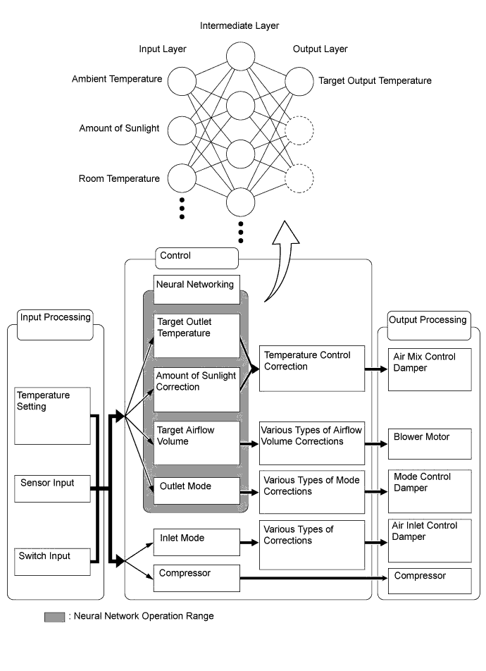
Previously, in automatic air conditioning systems without neural network control, the air conditioning amplifier assembly determined the required outlet air temperature and blower air volume in accordance with the calculation formula that has been obtained based on information received from the sensors. However, because the senses of a person are rather complex, a given temperature is sensed differently, depending on the environment in which the person is situated. For example, a given amount of solar radiation can feel comfortably warm in a cold climate, or extremely uncomfortable in a hot climate. Therefore, as a technique for effecting a higher level of control, a neural network has been adopted in the automatic air conditioning system. With this technique, the data that has been collected under varying environmental conditions is stored in the air conditioning amplifier. The air conditioning amplifier assembly can then effect control to provide enhanced air conditioning comfort.
-
The neural network control consists of neurons in the input layer, intermediate layer, and output layer. The input layer neurons process the input data of the ambient temperature, the amount of sunlight, and the room temperature based on the outputs of the switches and sensors, and output them to the intermediate layer neurons. Based on this data, the intermediate layer neurons adjust the strength of the links among the neurons. The sum of these is then calculated by the output layer neurons in the form of the required outlet temperature, solar correction, target airflow volume, and outlet mode control volume. Accordingly, the air conditioning amplifier controls the servo motors and blower motor in accordance with the control volumes that have been calculated by the neural network control.
-
-
-
CONSTRUCTION
-
Air Conditioning Control Assembly
-
An electric type air conditioning control assembly that has push switches and control dials is used.
-
The multi-information display is also used as the air conditioning display, making the air conditioning control assembly more compact.
-
As part of the right/left independent temperature control, the temperature control dials for the driver and the front passenger have been located closer to their respective seats for enhanced ease of use.
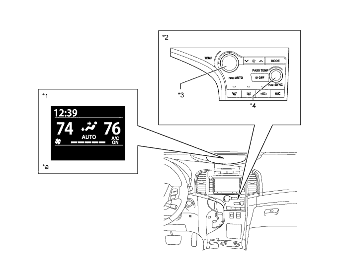
Text in Illustration *1 Multi-information Display *2 Air Conditioning Control Assembly *3 Temperature Control Dial (for LH) *4 Temperature Control Dial (for RH) *a Celsius temperature scale is used on destination package for Russia. - -
-
-
Air Conditioning Unit
-
The air conditioning unit consists of the evaporator, heater radiator unit sub-assembly, servo motors, evaporator temperature sensor (No. 1 cooler thermistor) and blower with fan motor sub-assembly.
-
The evaporator and heater radiator unit sub-assembly are mounted transversely to achieve a compact and lightweight form.
-
A bus connector is used in the wire harness connection that connects the servo motor to the air conditioning amplifier assembly.
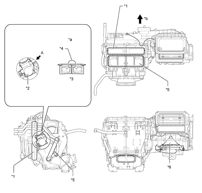
Text in Illustration *1 Evaporator *2 Air Mix Damper Servo Sub-assembly (for Front RH) *3 Air Mix Door *4 Linked *5 Heater Radiator Unit Sub-assembly *6 Blower with Fan Motor Sub-assembly *a View From A *b Front
-
-
Evaporator (No. 1 Cooler Evaporator Sub-assembly)
-
Placing the tanks at the top and the bottom of the evaporator and adopting a micropore tube construction has provided the following benefits:
-
Improved heat exchange efficiency
-
More uniform temperature distribution
-
A thinner evaporator
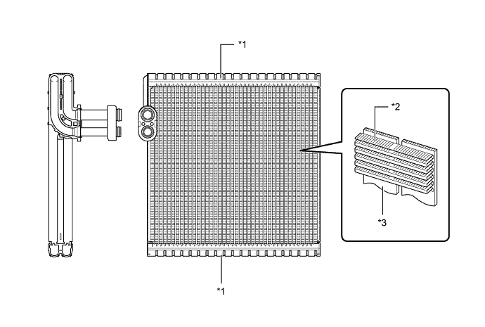
Text in Illustration *1 Tank *2 Cooling Fin *3 Micropore Tube - - -
-
-
Evaporator Temperature Sensor (No. 1 Cooler Thermistor)
-
The evaporator temperature sensor (No. 1 cooler thermistor) detects the temperature of the cool air immediately past the evaporator in the form of resistance changes, and outputs this data to the air conditioning amplifier assembly.
-
-
Heater Radiator Unit Sub-assembly
-
The compact, lightweight, and highly efficient Straight Flow Aluminum (SFA)-II type heater core is used for the air conditioning system.
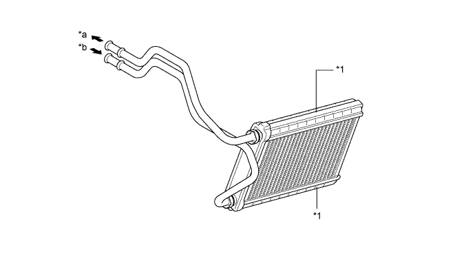
Text in Illustration *1 Tank - - *a OUT *b IN
-
-
Blower with Fan Motor Sub-assembly
-
The blower with fan motor sub-assembly has a built-in blower controller which is controlled by the air conditioning amplifier assembly.
-
-
Air Conditioning Harness Assembly
-
The air conditioning harness assembly has a built-in driver IC with a position detection function that communicates with each servo motor connector and actuates the servo motor.
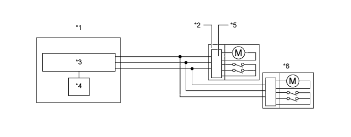
Text in Illustration *1 Air Conditioning Amplifier Assembly *2 Bus Connector *3 Communication IC *4 CPU *5 Communication Driver IC *6 Servo Motor
-
-
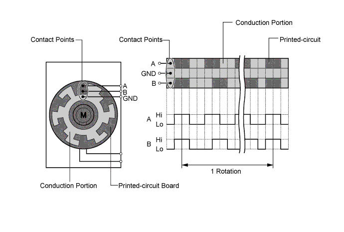
Servo Motor
-
The pulse pattern type servo motor consists of a printed circuit board and a servo motor. The printed circuit board has 3 contact points, and can transmit 2 on-off signals to the air conditioning amplifier based on the difference in the pulse phases. The bus connector can detect damper position and direction of movement with this signal.
-
-
Clean Air Filter
-
A pollen removal type clean air filter is used. This filter is made of polyester and excels in the removal of dust and pollen. Because the filter is made of polyester it can be disposed of easily as a non hazardous combustible material, a feature provided out of consideration for the environment.
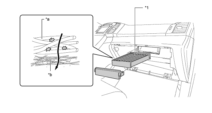
Text in Illustration *1 Clean Air Filter - - *a Large Foreign Object Filter Layer *b Electret Layer
-
-
Cooler Condenser Assembly
-
The cooler condenser assembly consists of 2 cooling portions: a condensing portion and a super-cooling portion. These portions are integrated with a gas-liquid separator (modulator). This cooler condenser assembly uses a sub-cool cycle that offers excellent heat-exchange performance.
-
In the sub-cool cycle, after the refrigerant passes through the condensing portion of the condenser, both the liquid refrigerant and the gaseous refrigerant that could not be liquefied are cooled again in the super-cooling portion. Thus, the refrigerant is sent to the evaporator in an almost completely liquefied state.
-
The desiccant and filter at the bottom of the modulator remove moisture and debris from the refrigerant.
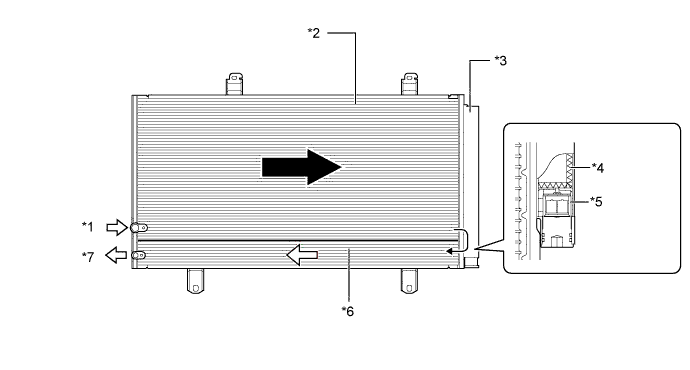
Text in Illustration *1 Gaseous Refrigerant *2 Condensing Portion *3 Modulator *4 Desiccant *5 Filter *6 Super-cooling Portion *7 Liquid Refrigerant - - Tech Tips
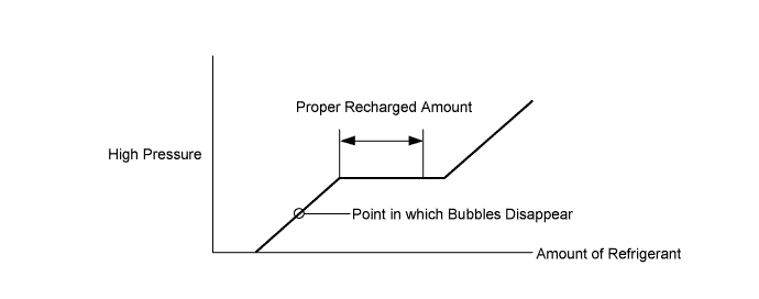
The point at which the air bubbles disappear in the refrigerant of the sub-cool cycle is lower than the proper amount of refrigerant with which the system must be filled. Therefore, if the system is recharged with refrigerant based on the point at which the air bubbles disappear, the amount of refrigerant would be insufficient. As a result, the cooling performance of the system would be affected. Overcharging the system with refrigerant will also lead to reduced performance. For the proper method of verifying the amount of refrigerant and for instructions on how to recharge the system with refrigerant, refer to the Repair Manual.
-
-
Compressor (Compressor with Pulley Assembly)
-
The compressor (compressor with pulley assembly) used is a continuously variable capacity type. Its capacity can be varied in accordance with the cooling load of the air conditioning.
-
The compressor (compressor with pulley assembly) consists of a pulley, shaft, lug plate, shoe, crank chamber, cylinder and solenoid control valve.
-
The solenoid control valve adjusts the suction pressure so that the compressor (compressor with pulley assembly) capacity can be controlled as desired.
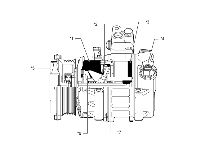
Text in Illustration *1 Crank Chamber *2 Shoe *3 Cylinder *4 Solenoid Control Valve *5 Pulley *6 Lug Plate *7 Shaft - -
-
-
Cooler (Room Temperature Sensor) Thermistor
-
The cooler (room temperature sensor) thermistor detects the room temperature based on changes in the resistance of its built-in thermistor. This signal is used by the air conditioning amplifier.
-
-
Cooler (Ambient Temperature Sensor) Thermistor
-
The cooler (ambient temperature sensor) thermistor detects the ambient temperature based on changes in the resistance of its built-in thermistor. This signal is used by the air conditioning amplifier.
-
-
Solar Sensor (Automatic Light Control Sensor)
-
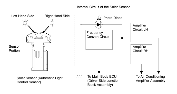
The automatic light control sensor consists of a photo diode, 2 amplifier circuits for the solar sensor, and a frequency converter circuit for the light control sensor.
-
The solar sensor detects (in the form of changes in the current that flows through the built-in photo diode) the changes in the amount of sunlight from its left hand and right hand sides (2 directions) and outputs these sunlight strength signals to the air conditioning amplifier.
-
-
-
OPERATION
-
Mode Position and Door Operation
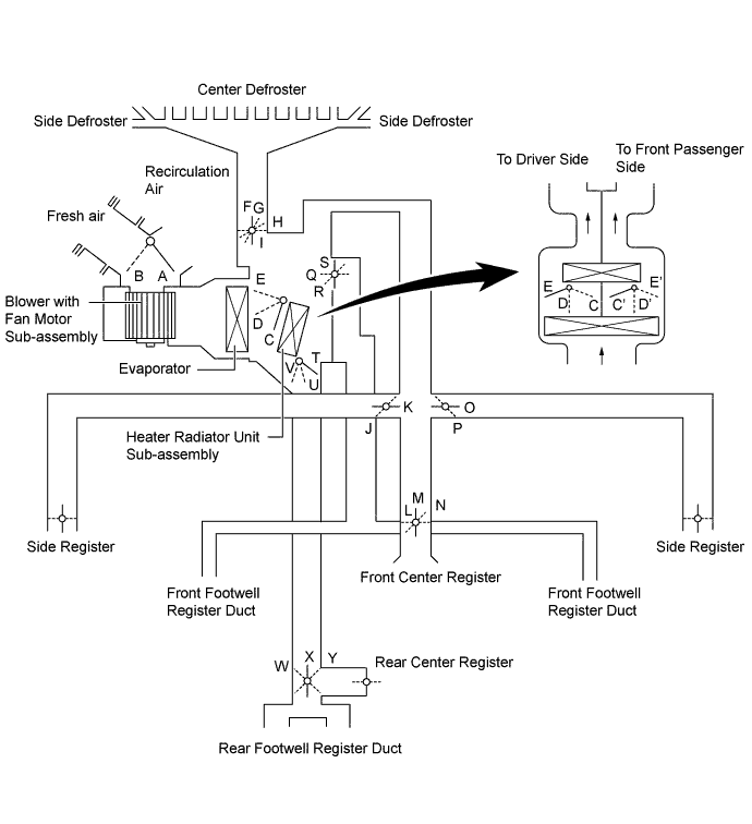
Control Door Operation Position Door Position Operation Air Inlet Control Door FRESH A Brings in fresh air. RECIRCULATION B Recirculates internal air. Air Mix Control Door MAX COLD to MAX HOT Temperature Setting C - D - E (C' - D' - E') T - U - V Varies the mixture ratio of warm air and cool air in order to regulate the temperature continuously between hot and cold. Mode Control Door 
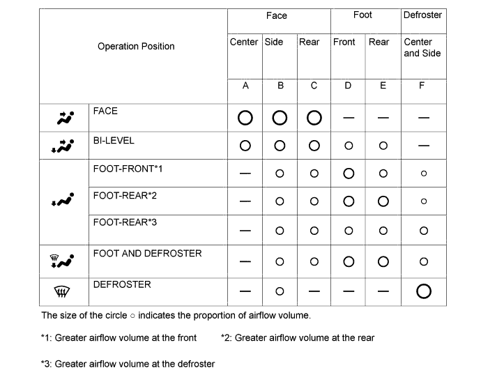
FACE I, K, M, O, S, W Air blows out of the front center register, rear center register, and side register ducts. 
BI-LEVEL I, K, N, O, R, X Air blows out of the front and rear center register, side register and front and rear footwell register ducts. 
FOOT H, J, L, P, Q, X Air blows out of the footwell register, rear center register, and side register ducts. In addition, air blows out slightly from the center defroster and side defroster. 
FOOT AND DEFROSTER G, J, L, P, Q, X Defrosts the windshield through the center defroster, side defroster, side register, and rear center register ducts, while air is also blown out from the front and rear footwell register ducts. 
DEFROSTER F, J, L, P, S, Y Defrosts the windshield through the center defroster, side defroster and side register ducts. -
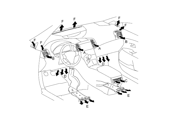
Air Outlets and Airflow Volume
-
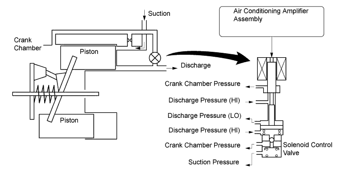
Compressor (Compressor with Pulley Assembly) Operation (Variable Capacity Operation)
-
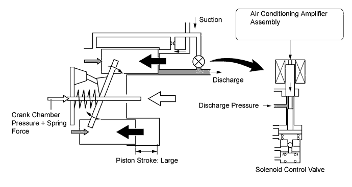
The crank chamber is connected to the suction passage. A solenoid valve is positioned between the suction passage (low pressure) and the discharge passage (high pressure).
-
The solenoid control valve operates under duty cycle control in accordance with the signals from the air conditioning amplifier assembly.
-
When the solenoid control valve closes (solenoid coil is energized), a difference in pressure is created and the pressure in the crank chamber decreases. Then, the pressure that is applied to the right side of the piston becomes greater than the pressure that is applied to the left side of the piston. This compresses the spring and tilts the swash plate. As a result, the piston stroke increases and the discharge capacity increases.
-
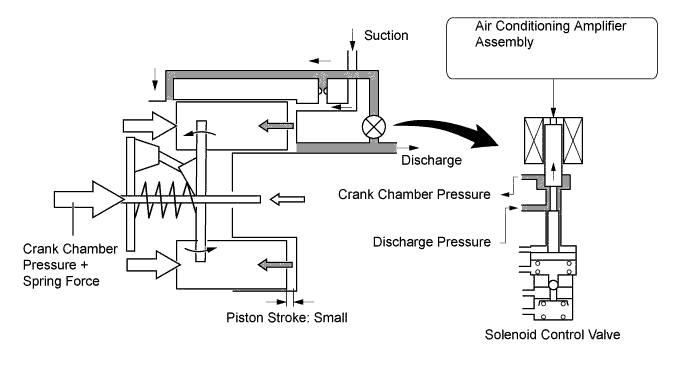
When the solenoid control valve opens (solenoid coil is not energized), the difference in pressure disappears. Then, the pressure that is applied to the left side of the piston becomes the same as the pressure that is applied to the right side of the piston. Thus, the spring elongates and eliminates the tilt of the lug plate. As a result, there is no piston stroke and the discharge capacity is reduced.
-
-
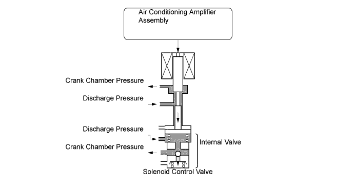
Internal Valve Operation
-
The internal valve operates when the compressor (compressor with pulley assembly) speed has increased rapidly, the compressor (compressor with pulley assembly) speed is high, or when thermal load has suddenly changed. As a result, the compressor (compressor with pulley assembly) capacity is reduced, increasing the durability of the compressor (compressor with pulley assembly).
-
-
-
DIAGNOSIS
-
The air conditioning amplifier assembly has a diagnosis function. It stores a record of any air conditioning system failures in its memory in the form of Diagnostic Trouble Codes (DTCs).
-
There are 2 methods for reading DTCs. One is to use the Global TechStream (GTS), and the other is to read the DTCs using the heater control panel display. For details, refer to the Repair Manual.
-