ACTIVE TORQUE CONTROL 4WD SYSTEM DETAILS
-
FUNCTION OF MAIN COMPONENTS
Component Function 4WD ECU Assembly
-
Controls the amperage applied to the electromagnetic control coupling solenoid based on signals provided by the sensors in order to appropriately distribute drive torque in accordance with driving conditions.
-
Turns AWD mode off when a parking brake on signal is received from the main body ECU (driver side junction block assembly).
-
Turns AWD mode off when a shift position signal (P or N) is received from the ECM.
Rear Differential Electromagnetic Control Coupling
- Electromagnetic Solenoid
Distributes drive torque in accordance with the amperage applied by the 4WD ECU assembly. Transfer Assembly Drive force input into the differential is redirected 90 degrees and output to the propeller shaft by the transfer assembly. Accessory Meter Assembly AWD Warning Light
-
Illuminates to warn the driver of a malfunction in the active torque control 4WD system.
-
Blinks to inform the driver of the DTCs in the diagnostic mode.
Speed Sensor Detects the wheel speed of each wheel. Crankshaft Position Sensor Detects the engine speed and outputs it to the ECM. Throttle Position Sensor Detects the throttle valve position and outputs it to the ECM. Park/Neutral Position Switch Assembly Detects the shift position of the transaxle and outputs it to the ECM. Stop Light Switch Assembly Detects when the brake pedal is depressed. Parking Brake Switch Assembly Detects when the parking brake is applied. ECM Outputs signals such as the shift position signal, throttle position signal, and crankshaft position signal to the 4WD ECU assembly. Skid Control ECU (Brake Actuator Assembly) Outputs signals such as the vehicle speed signal and deceleration signal to the 4WD ECU assembly. Main Body ECU (Driver Side Junction Block Assembly) Outputs signals such as the parking brake signal to the 4WD ECU assembly. -
-
CONSTRUCTION
-
Transfer Assembly
-
The compact and lightweight MF1A transfer is used.
-
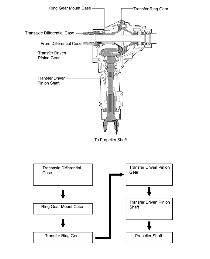
Drive force input into the differential is redirected 90 degrees and output to the propeller shaft by the transfer assembly.
-
The offset between the transfer ring gear and the transfer driven pinion gear is increased, the distance between the driven pinion bearings is reduced, and a small-diameter ring gear mount bearing is used. As a result, the transfer assembly is easier to install.
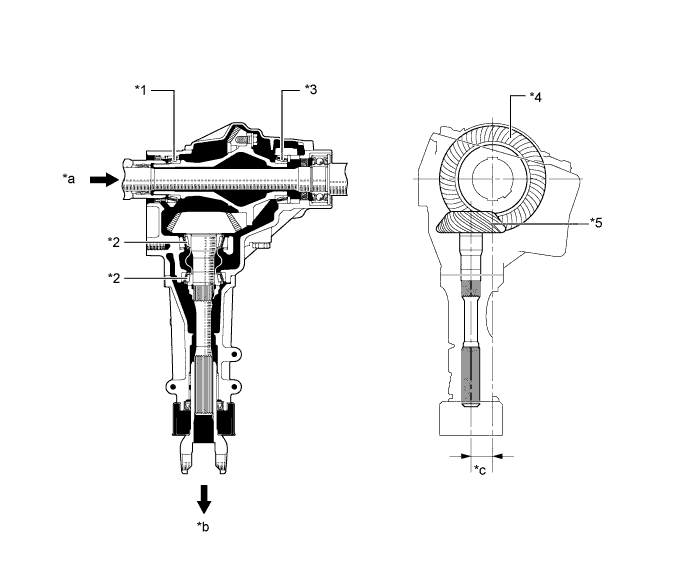
Text in Illustration *1 Ring Gear Mount Bearing *2 Driven Pinion Bearing *3 Ring Gear Mount Bearing *4 Transfer Ring Gear *5 Transfer Driven Pinion Gear - - *a Drive Force Input *b Drive Force Output *c Offset between the transfer ring gear and the transfer driven pinion gear - - Transfer Type MF1A Gear Type Hypoid Gear Gear Ratio 0.439 Transfer Ring Gear The No. of Teeth 41 Transfer Driven Pinion Gear The No. of Teeth 18 Oil Viscosity Above -18°C (0°F): SAE 90 Below -18°C (0°F): SAE 80W or SAE 80W-90 Oil Grade API GL-5 Oil Type Hypoid Gear Oil Oil Capacity Liters (US qts, Imp. qts) 0.8 (0.84, 0.70) Weight (Reference)* kg (lb) 15.4 (33.9) *: Weight shows the figure with the oil fully filled.
-
The illustration below shows the flow of power from the transaxle.
-
-
-
OPERATION
-
2WD Mode
-
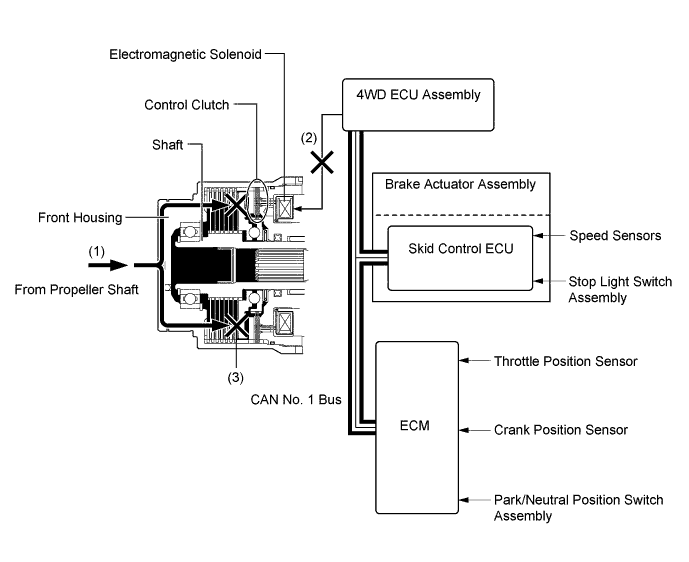
The drive force is transmitted from the propeller shaft to the front housing.
-
The 4WD ECU assembly judges whether it is necessary to send drive torque to the rear wheels based on input from various sensors. When it is not necessary to send drive torque to the rear wheels, the electromagnetic solenoid is not operated.
-
The drive force of the front housing is not transmitted to the shaft because the control clutch is not engaged.
-
Accordingly, drive force from the propeller shaft is not transmitted to the rear wheels.
-
-
AWD Mode
-
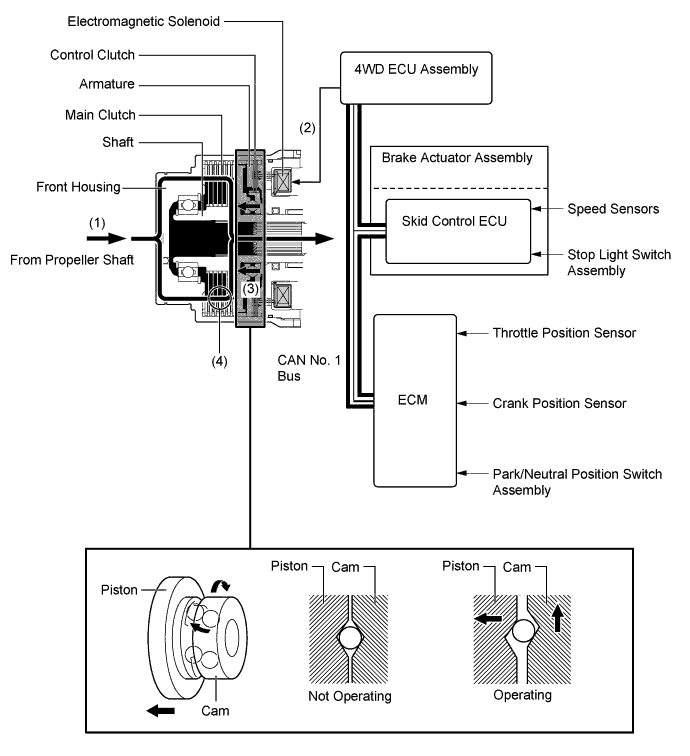
The drive force is transmitted from the propeller shaft to the front housing.
-
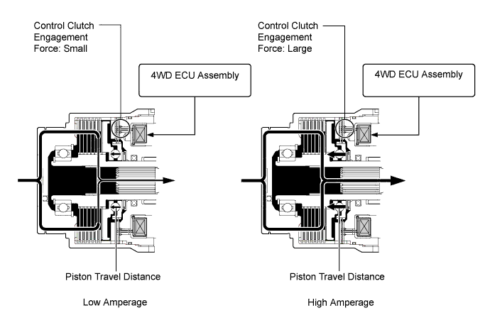
The 4WD ECU assembly judges whether it is necessary to send drive torque to the rear wheels based on input from various sensors. When it is necessary to send drive torque to the rear wheels, the electromagnetic solenoid is operated.
-
The electromagnetic solenoid attracts the armature to the control clutch side. This causes the control clutch to engage and the cam to rotate.
-
The rotational movement of the cam causes the piston to push on the main clutch, causing the main clutch to engage.
-
The amount of drive force that is transmitted to the rear wheels is controlled steplessly by controlling the amperage that is applied to the electromagnetic solenoid.
-
Accordingly, drive force from the propeller shaft is transmitted to the rear wheels.
-
-
-
DIAGNOSIS
-
When the 4WD ECU assembly detects a malfunction, it will record information related to the fault. Furthermore, the AWD warning light in the accessory meter assembly will illuminate to inform the driver.
-
At the same time, Diagnostic Trouble Codes (DTCs) are stored in memory. The DTCs can be read using the Global TechStream (GTS).
-
For details of the DTCs that are stored in 4WD ECU assembly memory, refer to the Repair Manual.
-
-
FAIL-SAFE
-
When there is a possibility of causing damage to the drivetrain due to a malfunction in the active torque control 4WD system or rough driving, the system illuminates or blinks the AWD warning light to inform the driver, stops AWD mode, and enables the vehicle to operate in front-wheel-drive mode.
Condition AWD Warning Light AWD system malfunction Illuminates Rough driving in AWD mode Fast Blinking Tech Tips
When the 4WD ECU assembly judges that the vehicle has stabilized, it resumes AWD mode. If the AWD warning light blinks, take the following actions without turning the engine OFF:
-
Decelerate the vehicle until the light goes out.
-
Stop the vehicle and wait until the light goes out.
-
-