FUEL SYSTEM DETAILS
-
CONSTRUCTION
-
Fuel Delivery Pipe Sub-assembly
-
A fuel delivery pipe sub-assembly made of steel is used to ensure strength.
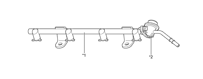
Text in Illustration *1 Fuel Delivery Pipe Sub-assembly *2 Fuel Pressure Pulsation Damper Assembly
-
-
Fuel Tank Assembly
-
A fuel tank assembly made of lead-free sheet steel is used.
-
The fuel tank assembly adopts a saddle shape to allow the propeller shaft to pass under the center portion of the tank. Also, a jet pump is used to transfer fuel from the side of the tank without the fuel pump to the side with the fuel pump.
-
The propeller shaft is located below the raised center of the bottom of the fuel tank assembly. The fuel tank assembly is shaped as indicated below. A fuel tank assembly with such a shape tends to cause fuel to be present in both chamber A and chamber B when the fuel level is low. This stops the fuel in chamber B from being pumped out. To prevent this from occurring, a jet pump has been provided to transfer the fuel from chamber B to chamber A. This is accomplished by utilizing the flow of the fuel through the jet pump, so that the pressure difference created by the fuel as it passes through the venturi, is used to suck the fuel out of chamber B and send it to chamber A.
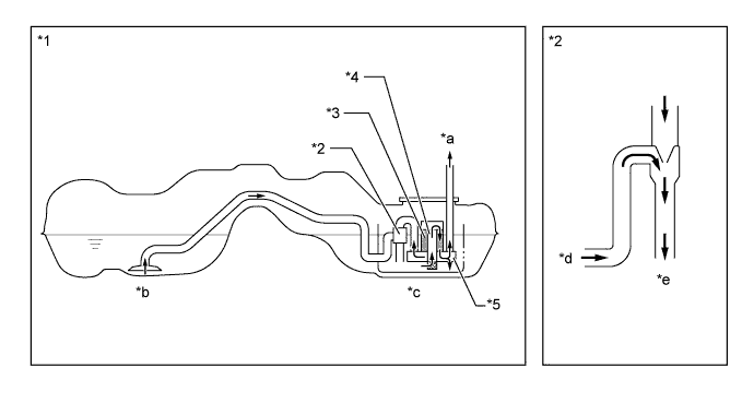
Text in Illustration *1 Fuel Tank Assembly *2 Jet Pump *3 Fuel Filter Assembly *4 Fuel Pump *5 Fuel Pressure Regulator Assembly - - *a To Engine *b Chamber B *c Chamber A *d From Chamber B *e To Chamber A (Reservoir) - -
-
-