PRE-CRASH SAFETY SYSTEM (w/o Driver Monitor Camera) DETAILS
-
FUNCTION OF MAIN COMPONENTS
Item Function Combination Meter Assembly PCS Warning Light Illuminates or flashes to warn the driver in accordance with signals from the seat belt control ECU. Multi-information Display Displays a warning message to inform or warn the driver of the system condition in accordance with signals from the seat belt control ECU. Master Warning Light Illuminates to warn the driver in accordance with signals from the seat belt control ECU. Multi Buzzer Sounds to warn the driver in accordance with signals from the driving support ECU assembly when the system is malfunctioning. Millimeter Wave Radar Sensor Assembly Radiates the millimeter wave radar forward, uses the reflected millimeter wave for detecting the presence of a vehicle ahead, the vehicle-to-vehicle distance and the relative speed, and then transmits this information to the driving support ECU assembly. Front Seat Outer Belt Assembly Seat Belt Motor Retracts the seat belt in accordance with signals received from the seat belt control ECU. Front Seat Inner Belt Assembly (Driver) Buckle Switch Detects the condition (verifies if the belt is fastened) of the driver seat belt and transmits a signal to the center airbag sensor assembly. Front Seat Inner Belt Assembly (Passenger) Buckle Switch Detects the condition (verifies if the belt is fastened) of the front passenger seat belt and transmits a signal to the center airbag sensor assembly. Center Airbag Sensor Assembly Transmits the condition (fastened or unfastened) of the driver and front passenger seat belts to the seat belt control ECU. Driving Support ECU Assembly Makes judgments on whether a collision is unavoidable based on the information received from the millimeter wave radar sensor assembly. It then outputs a seat belt operation signal and brake assist standby request signal and pre-crash brake request signal if required. Seat Belt Control ECU Receives a seat belt operation request signal from the driving support ECU assembly or skid control ECU assembly and operates the seat belts. Brake Actuator Assembly Brake Actuator Actuates the brakes in accordance with the signals from the skid control ECU assembly. Master Cylinder Pressure Sensor Detects the master cylinder pressure and transmits a signal to the skid control ECU assembly. Wheel Cylinder Pressure Sensor Detects the wheel cylinder pressure and transmits a signal to the skid control ECU assembly. Skid Control ECU Assembly
-
Receives a brake assist standby request signal from the driving support ECU assembly and switches the brake assist to standby mode. When a stop light switch assembly signal is input, the skid control ECU assembly activates the brake assist.
-
Operates the pre-crash brake if the skid control ECU assembly receives a pre-crash brake operation request signal from the driving support ECU assembly.
-
Receives the warning brake activation request signal from the driving support ECU assembly and operates the warning brake.
-
Determines if the brakes have been applied suddenly through signals received from the master cylinder pressure sensor, and outputs a seat belt operation signal to the seat belt control ECU.
-
Determines the occurrence of a front or rear wheel skid tendency, and outputs a seat belt operation signal to the seat belt control ECU.
-
Transmits vehicle speed signals to the driving support ECU assembly.
Suspension Control ECU Upon receiving an air suspension control request signal from the driving support ECU assembly, the suspension control ECU optimizes the amount of dampening of the suspension shock absorbers in order to suppress nose-diving during braking and rolling during steering. Stop Light Switch Assembly Detects if the brake pedal is depressed and transmits a signal to the skid control ECU assembly. Speed Sensor Detects speed of each wheel and transmits the signals to the skid control ECU assembly. Yawrate Sensor Detects the yaw rate and lateral/longitudinal deceleration of the vehicle and transmits a signal to the skid control ECU assembly and the driving support ECU assembly. Steering Sensor Detects the angle and direction of steering and transmits a signal to the skid control ECU assembly and the driving support ECU assembly. Precrash System Cancel Switch Assembly Disables the pre-crash brake operation when the switch is turned on. The PCS warning light illuminates to show that the pre-crash brakes off. Skid Control Buzzer Assembly Sounds to warn the driver in accordance with signals from the skid control ECU assembly. -
-
OPERATING CONDITION
-
The pre-crash safety system operates in the following components. The impact dampening components are as shown below:
Impact Dampening Component Operation Condition Pre-crash Warning Control
-
Power switch is on (IG).
-
Precrash system cancel switch is not pushed.
-
Vehicle speed is approx. 15 km/h (10 mph) or above.
-
Oncoming vehicle relative speed is approx. 15 km/h (10 mph) or above.
Pre-crash Brake Assist Control
-
Power switch is on (IG).
-
Precrash system cancel switch is not pushed.
-
VSC OFF switch is not pushed.
-
Vehicle speed is approx. 30 km/h (20 mph) or above.
-
Oncoming vehicle relative speed is approx. 30 km/h (20 mph) or above.
Pre-crash Seat Belt Control (Sudden Brake or Serious Vehicle Skid Control in Conjunction)
-
Power switch is on (IG).
-
Precrash system cancel switch is not pushed.
-
Seat belt is buckled.
-
Brakes are suddenly applied.
-
System determines a loss of vehicle control.
-
Vehicle speed is approx. 30 km/h (20 mph) or above.
-
Pre-crash Seat Belt Control (Operates in Conjunction with Radar)
-
Air Suspension Control
-
Power switch is on (IG).
-
Precrash system cancel switch is not pushed.
-
Seat belt is buckled.
-
Vehicle Speed is approx. 5 km/h (4 mph) or above.
-
Oncoming vehicle relative speed is approx. 30 km/h (20 mph) or above.
Pre-crash Brake Control*
-
Power switch is on (IG).
-
VSC OFF Switch is not pushed.
-
Precrash system cancel switch is not pushed.
-
Vehicle speed is approx. 15 km/h (10 mph) or above.
-
Oncoming vehicle relative speed is approx. 15 km/h (10 mph) or above.
-
*: Models with pre-crash brake control
-
-
If precrash system cancel switch assembly is turned on, the pre-crash safety system does not operate.
-
-
SYSTEM CONTROL
-
Loss of Vehicle Control
(1) While the vehicle is traveling at approx. 30 km/h (20 mph) or more, the skid control ECU assembly determines if skid recovery will be difficult based on the signals from the steering sensor, yawrate sensor and speed sensors. (2) The skid control ECU assembly sends a seat belt operation request signal to the seat belt control ECU. (3) The seat belt control ECU determines the seat belt motor operating conditions based on this signal and seat belt buckle switch signals. Then, the seat belt control ECU retracts the slack in the seat belts by operating the seat belt motors. (4) The seat belts return to a normal state when the relevant conditions of the vehicle have stabilized. 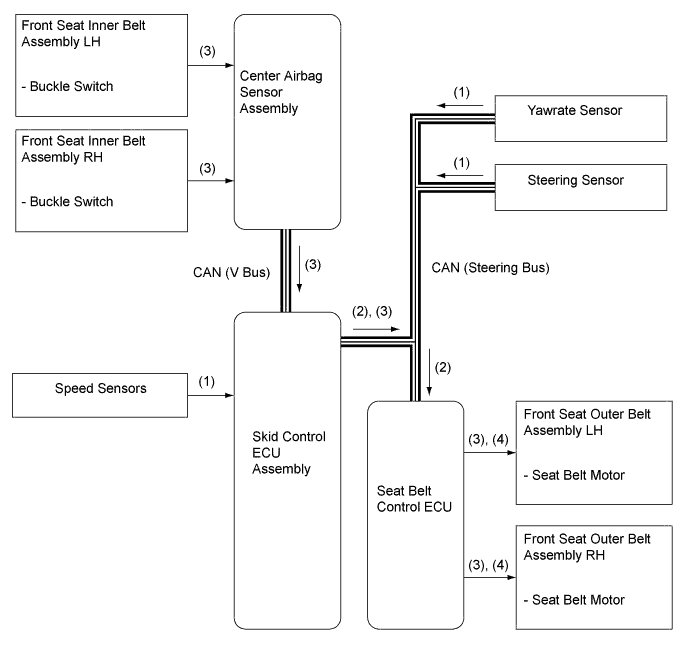
-
Sudden Braking
(1) While the vehicle is traveling at approx. 30 km/h (20 mph) or more, the skid control ECU assembly can determine a sudden braking condition based on the signals from the master cylinder pressure sensor, stop light switch assembly and speed sensors. (2) At this time, the skid control ECU assembly outputs a seat belt operation request signal to the seat belt control ECU. (3) The seat belt control ECU determines the seat belt motor operating conditions based on this signal and seat belt buckle switch signals. Then, the seat belt control ECU retracts the slack in the seat belts by operating the seat belt motors. (4) The seat belts return to a normal state when the brake pedal is released. 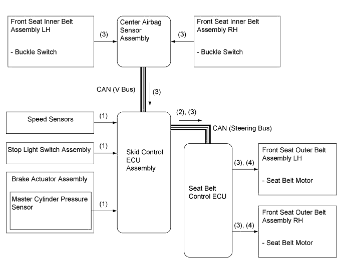
-
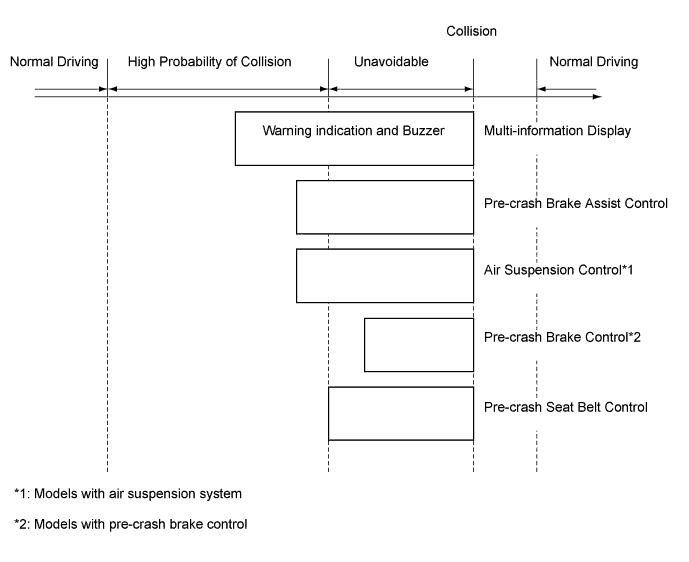
High Possibility of Collision or Unavoidable Collision
-
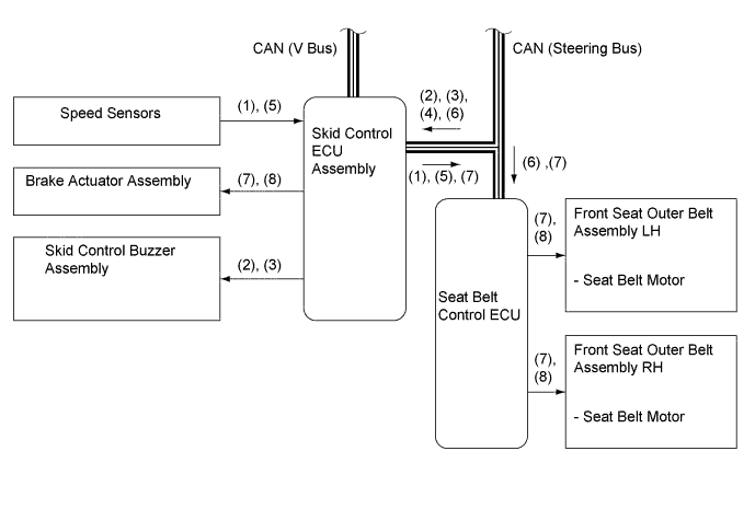
The diagram below shows the flow of the activation of the systems during a pre-crash safety system operation:
-
Operation
(1) The driving support ECU assembly determines that the possibility of a collision is high based on the signals received from the millimeter wave radar sensor assembly, steering sensor, speed sensors and yawrate sensor. (2) At this time, the driving support ECU assembly outputs a caution display request signal to the multi-information display (combination meter assembly) and a skid control buzzer assembly request signal to the skid control ECU assembly. (3) When the driving support ECU assembly determines that the possibility of an unavoidable collision is high as in step 1, it outputs a brake warning display request signal to the multi-information display (combination meter assembly) and a skid control buzzer request signal to the skid control ECU assembly. (4) At this time, the driving support ECU assembly outputs an air suspension control request signal to the suspension control ECU and a pre-crash brake assist request signal to the skid control ECU assembly. Upon receiving this signal, the skid control ECU assembly switches the brake assist to the standby condition. (5) The driving support ECU assembly determines that an unavoidable collision condition exists based on the signals received from the millimeter wave radar sensor assembly, speed sensors, steering senso, and yawrate sensor. (6) At this time, the driving support ECU assembly outputs a seat belt operation request signal to the seat belt control ECU, a pre-crash brake request signal to the skid control ECU assembly. (7) The seat belt control ECU determines the seat belt motor operation condition based on this signal and the seat belt buckle switch signal, and retracts the slack in the seat belts by operating the seat belt motors. At the same time, the skid control ECU assembly activates the brake actuator assembly as a pre-crash brake control. (8) If no collision occurs, the seat belts, the brake assist and air suspension returns to their normal states. 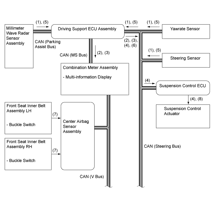
-
-
-
FUNCTION
-
Warning Messages Displayed in Combination Meter Assembly
-
The combination meter assembly uses the master warning light, PCS warning light, multi buzzer and multi-information display to provide the driver with pre-crash safety system warnings and indications.
-
If the driving support ECU assembly determines that there is a possibility of a collision, it sends a signal to the combination meter assembly. Upon receiving this signal, the combination meter assembly indicates a warning on the multi-information display, master warning light and PCS warning light. The details are indicated below.
-
If the driving support ECU assembly determines that the possibility of a collision is high, it sends a signal to the combination meter assembly. Upon receiving this signal, the combination meter indicates a warning on the multi-information display, master warning light, PCS warning light and sounds the skid control buzzer assembly. The details are indicated below:
When there is a high possibility of a collision Multi-information Display Detail Skid Control Buzzer Assembly 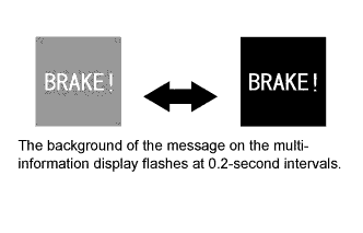
The driving support ECU assembly has determined that the possibility of a collision is even higher than the above. Sounds Continuously -
The 3 types of warning messages are used for the pre-crash safety system as described below. The pre-crash safety system does not operate when these messages appear in the combination meter assembly.
Multi-information Display Detail Master Warning Light PCS Warning Light Multi Buzzer DTC 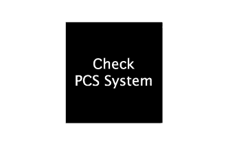
This message appears when the seat belt control ECU detects a system malfunction. Illuminates Illuminates Sounds Once ○ 
This message appears when the seat belt control ECU determines that any of the following conditions exist:
-
Dirty millimeter wave radar sensor assembly
-
Poor weather condition
-
Overheated seat belt control ECU
After these conditions have been resolved, the system will operate normally.
Illuminates Flashes Sounds Once X 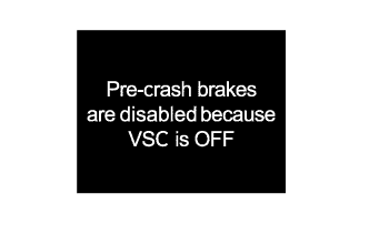
This message appears when the VSC OFF switch has been pushed.
The message is displayed for 3 seconds after the VSC OFF switch is operated.
- - - X Tech Tips
○ : Repair is required/DTCs are output
X: Repair is not required/DTCs are not output
-
-
-
-
CONSTRUCTION
-
Millimeter Wave Radar Sensor Assembly
-
The millimeter wave radar sensor assembly consists of a millimeter wave radar circuit, signal processing circuit and CPU.
-
The millimeter wave radar outputs waves when the vehicle speed is above 0 km/h (0 mph), and not when the vehicle speed is at 0 km/h (0 mph). The millimeter wave radar uses frequencies in the 76.5 GHz band.
-
The reception antennas receive the millimeter wave radar waves that have been reflected.
-
The signal processing circuit detects the distance, relative speed and the direction of the object by generating millimeter wave radar waves and calculating the signals received by the reception antennas. Then, the signal processing circuit transmits this information to the driving support ECU assembly.
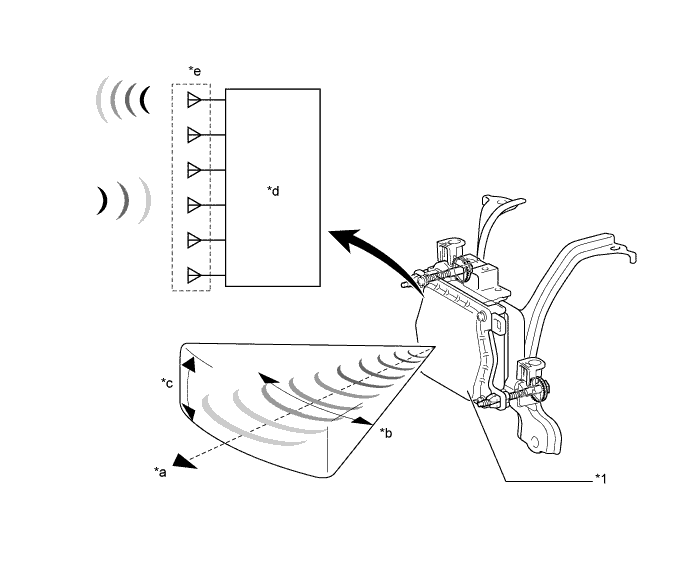
Text in Illustration *1 Millimeter Wave Radar Sensor Assembly - - *a Detection Distance: Approx. 150 m (490 ft.) *b Horizontal Angle: Approx. 20° *c Vertical Angle: Approx. 8° *d Signal Processing Circuit *e Millimeter Wave Radar Circuit - - -
The distance to the object, azimuth (horizontal angle) and relative speed are calculated from the information that is provided by the reflection millimeter wave radar wave as described below:
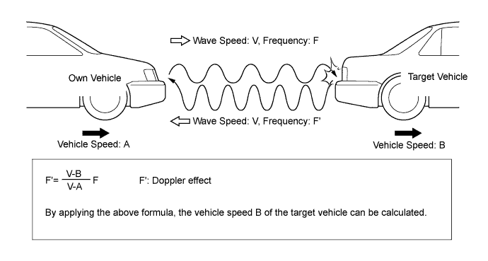
Item Calculation Method Distance Calculated from the length of time that has elapsed from the time the waves of the millimeter wave radar sensor assembly have been emitted, until the waves reflected by the millimeter wave radar sensor assembly is received. The detection distance is approx. 150 m (490 ft.). Azimuth Calculated from the angle of the waves reflected by the millimeter wave radar sensor assembly that have been received. The detection angle has a horizontal angle of approx. 20° and a vertical angle of approx. 8°. Relative Speed Calculated by utilizing the changes (Doppler effect*) that occur in the frequencies of the reflected millimeter wave radar waves. Tech Tips
*: The Doppler effect causes the observer to perceive the radio waves emitted by a moving object to be of higher frequencies as it approaches, and to be of lower frequencies as it recedes.
-
-