FOUR WHEEL DRIVE CONTROL SYSTEM DETAILS
-
CONSTRUCTION
-
Transfer Assembly
-
This transfer drives the front output shaft (output shaft companion flange sub-assembly) through the transfer idler gear assembly and uses a center differential (No. 1 differential case sub-assembly) that is integrated into the rear output shaft, thus making the transfer more compact.
-
When the motive force is input via the transfer input shaft, the center differential (No. 1 differential case sub-assembly) distributes the motive force to the front output shaft (output shaft companion flange sub-assembly) and the rear output shaft.
-
The transfer idler gear assembly has improved tooth surface accuracy to reduce gear noise.
-
The front transfer case also has an integrated oil pump mechanism.
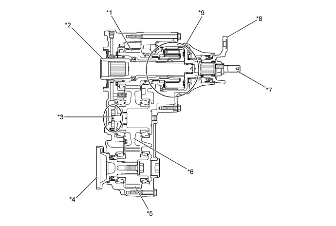
Text in Illustration *1 Transfer Front Drive Gear Assembly *2 Transfer Input Shaft *3 Oil Pump Mechanism *4 Front Output Shaft (Output Shaft Companion Flange Sub-assembly) *5 Transfer Counter Gear Assembly *6 Transfer Idler Gear Assembly *7 Rear Output Shaft *8 Drive Pinion Companion Flange Sub-assembly *9 Center Differential (No. 1 Differential Case Subassembly) - -
-
-
Center Differential (No. 1 Differential Case Sub-assembly)
-
The center differential (No. 1 differential case sub-assembly) uses a TORSEN LSD.
-
TORSEN LSD is a torque sensing LSD that generates limited differential torque proportional to the vehicle's drive torque.
-
The TORSEN LSD consists of a ring gear, 8 pinion gears, sun gear, planetary carrier, bearing, washer plate and rear output shaft. The sun gear is connected to the front wheel side and the ring gear is connected to the rear wheel side.
-
The TORSEN LSD operates when a wheel speed difference occurs between the front and rear wheels and optimally distributes the motive force from the transmission. As a result, traction and cornering performance have been improved.
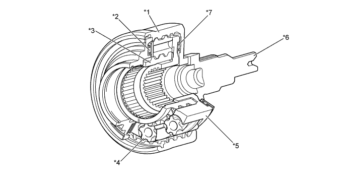
Text in Illustration *1 Ring Gear *2 Bearing *3 Sun Gear *4 Pinion Gear *5 Planetary Carrier *6 Rear Output Shaft *7 Washer Plate - - 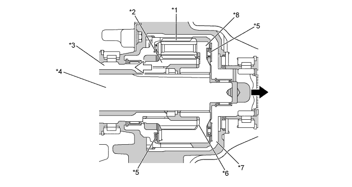
Text in Illustration *1 Pinion Gear *2 Sun Gear *3 Transfer Front Drive Gear Assembly *4 Transfer Input Shaft *5 Bearing *6 Washer Plate *7 Ring Gear *8 Planetary Carrier 
Front Wheel Side 
Rear Wheel Side -
The torque distribution ratio of the front and rear wheels changes in accordance with vehicle conditions as described in the table below:
Torque Distribution Ratio Wheel Speed Distribution Ratio (Front Wheel Torque : Rear Wheel Torque) Acceleration Deceleration 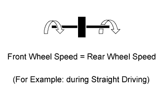
40 : 60 40 : 60 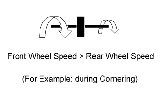
31 : 69 50 : 50 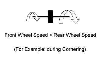
48 : 52 30 : 70
-
-
Oil Pump Mechanism
-
A trochoid gear type oil pump is used for lubricating inside the transfer. This oil pump is driven by the transfer idler gear assembly via the transfer oil pump drive shaft.
-
The oil pump body is integrated into the front transfer case to reduce the weight of the transfer.
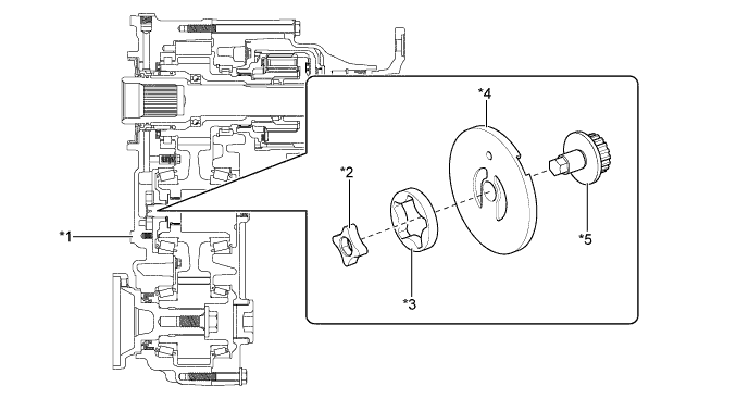
Text in Illustration *1 Front Transfer Case *2 Transfer Oil Pump Drive Rotor *3 Transfer Oil Pump Driven Rotor *4 Transfer Oil Pump Plate Sub-assembly *5 Transfer Oil Pump Drive Shaft - -
-
-
-
OPERATION
-
Center Differential (No. 1 Differential Case Sub-assembly)
-
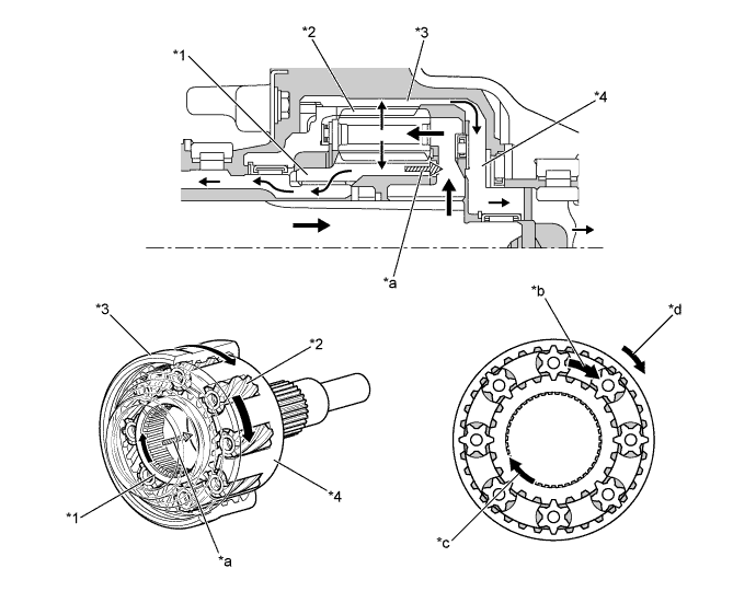
During cornering, the rotational speed of the sun gear (front wheel side) is different from that of the ring gear (rear wheel side), and the pinion gear rotates on its axis. At this time, a separating force is produced from the pinion gear in the direction in which it is disengaging from the sun gear and ring gear, since the pinion gear has spiral teeth. As a result, the pinion gear is pressed against the wall surface of the planetary carrier where the pinion gear is housed.
-
Friction resistance occurs between the pinion gear and the planetary carrier. This friction resistance causes the pinion gear to stop rotating and makes the gear on the low speed rotation side rotate. As a result, the rotating speed difference between the sun gear and the ring gear is reduced and motive force is distributed from the high speed rotation side to the low speed rotation side.

Text in Illustration (Operation Image during Straight Driving) *1 Sun Gear (Front Wheel Side) *2 Ring Gear (Rear Wheel Side) *3 Planetary Carrier *4 Pinion Gear *a Front Output Speed *b Rear Output Speed *c Input Speed - - 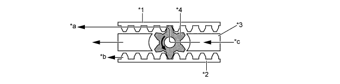
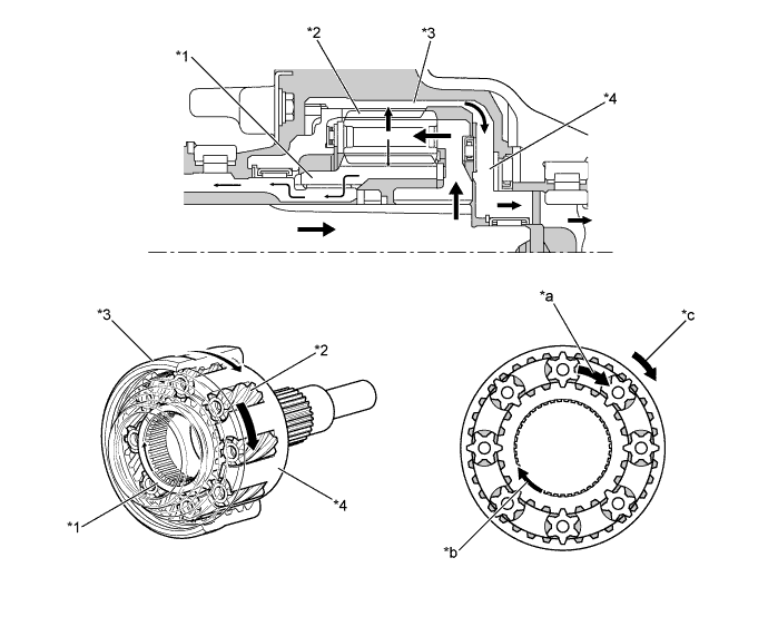
Text in Illustration (Operation Image while Cornering before LSD Activation) *1 Sun Gear (Front Wheel Side) *2 Ring Gear (Rear Wheel Side) *3 Planetary Carrier *4 Pinion Gear *a Front Output Speed *b Rear Output Speed *c Input Speed - - 
Text in Illustration (Operation Image while Cornering during LSD Activation) *1 Sun Gear (Front Wheel Side) *2 Ring Gear (Rear Wheel Side) *3 Planetary Carrier *4 Pinion Gear *a Front Output Speed *b Rear Output Speed *c Input Speed *d Pinion Gear Comes into Contact with Planetary Carrier (Limited Differential Torque is Produced) -
There is no difference in rotational speed between the sun gear and the ring gear during straight driving. Therefore, torque is transferred to the front wheels and rear wheels without rotating the pinion gear. The torque distribution ratio during straight driving is 40/60 (front/ rear).
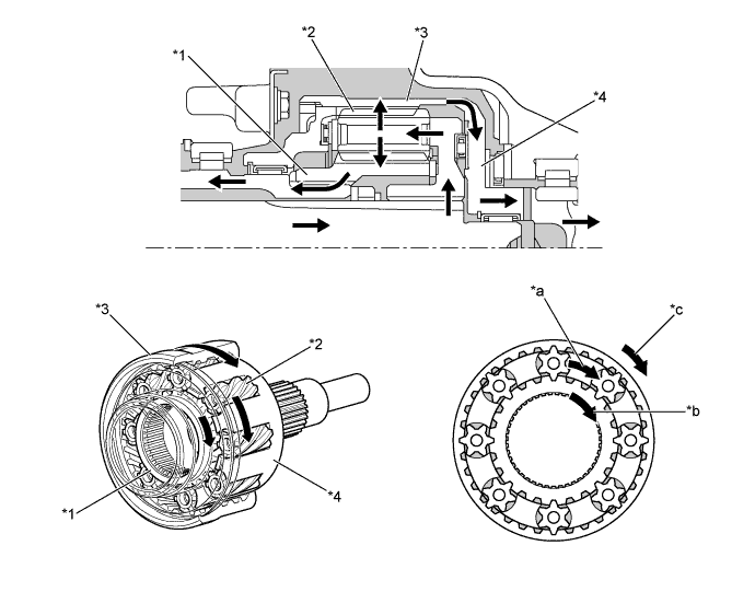
Text in Illustration (Operation during Straight Driving) *1 Sun Gear (Front Wheel Side) *2 Pinion Gear *3 Ring Gear (Rear Wheel Side) *4 Planetary Carrier *a Input Torque *b Front Output Torque *c Rear Output Torque - - Power Flow - - 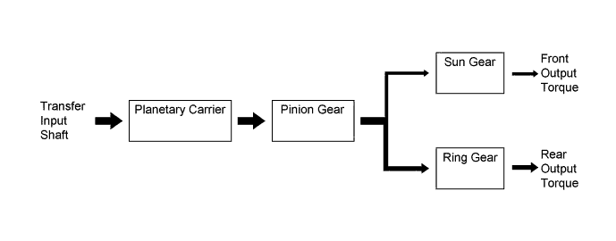
-
When the front wheel speed is faster than the rear wheel speed, the sun gear rotates faster than the ring gear. At this time, the torque distribution ratio changes to 31/69 (front/rear), thus suppressing front wheel skid tendency of the vehicle and improving cornering ability.
-
When the rear wheel speed is faster than the front wheel speed, the ring gear rotates faster than the sun gear. At this time, the torque distribution ratio changes to 48/52 (front/rear), thus suppressing rear wheel skid tendency of the vehicle and ensuring vehicle stability during cornering.
Text in Illustration (Torque Distribution Ratio 31/69) *1 Sun Gear (Front Wheel Side) *2 Pinion Gear *3 Ring Gear (Rear Wheel Side) *4 Planetary Carrier *a Input Torque *b Front Output Torque *c Rear Output Torque - - Power Flow - - 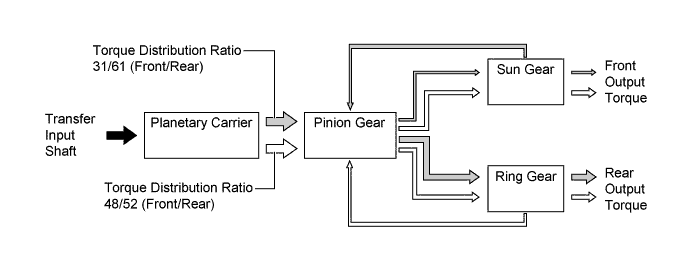
-
In addition to friction resistance produced between the pinion gear and the planetary carrier during deceleration while cornering, friction resistance is also produced when the sun gear is engaged with the ring gear via the pinion gear, moves to the right as shown in the illustration below and is pressed against the washer plate. The torque distribution ratio changes to 50/50 (front/ rear) due to friction resistance when the front wheel speed is faster than the rear wheel speed. When the rear wheel speed is faster than the front wheel speed, the torque distribution ratio changes to 30/70 (front/rear). Thus, vehicle stability during deceleration while cornering has been ensured.
Text in Illustration (Torque Distribution Ratio 50/50) *1 Sun Gear (Front Wheel Side) *2 Pinion Gear *3 Ring Gear (Rear Wheel Side) *4 Planetary Carrier *a Pressure to Washer Plate *b Input Torque *c Front Output Torque *d Rear Output Torque Power Flow - - 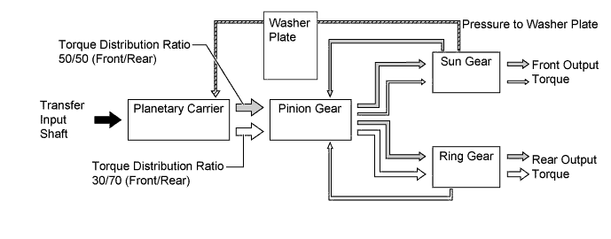
-
-