BODY STRUCTURE DETAILS
-
FUNCTION
-
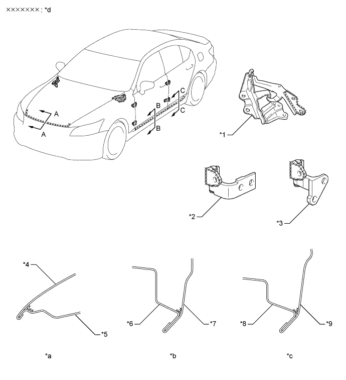
Impact Absorbing Structure for Frontal Collision
-
A structure that ensures collision energy absorption efficiency, dissipates impact, and minimizes cabin deformation during a frontal collision has been achieved. This construction uses highly efficient crush boxes (front bumper mounting reinforce sub-assembly), front side members (front side member sub-assembly inner), and frame side rail rear for collision, as front pillars and front door inner reinforcements made with ultra high-tensile strength sheet steel.
-
A large front bumper reinforcement is used to efficiently dissipate the impact energy to the right and left front side members.
-
Highly efficient crush boxes made of extruded aluminum are provided at the front ends of the front side members. These crush boxes reduce the impact that acts on the front side members and minimize body deformation during minor collision.
-
The front side member is constructed as shown in the A - A cross sectional diagram, realizing high proof strength and excellent impact energy absorption efficiency.
-
A frame side rail rear for collision, which dissipates the impact of a collision, is provided at the front suspension crossmember sub-assembly (2WD) / front frame assembly (AWD) to realize compatibility as well as a high level of collision performance.
-
As one of the measures to dissipate the impact during a frontal offset collision, the front door outside panel reinforcement has been constructed to transmit impact, thus reducing the load that is applied to the front pillars. The front body pillar reinforcement upper outer and front door inside reinforcement No. 1 are made of high-tensile strength steel.
-
The front ends of the rockers protrude forward of the vehicle. Upon receiving the impact of a frontal offset collision from the front tires, the front ends of the rockers absorb the energy to minimize the deformation of the body around the cabin.
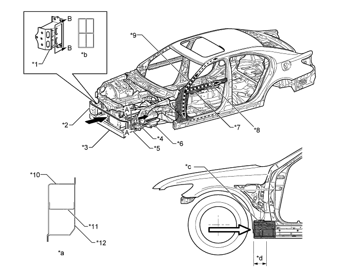
Text in Illustration *1 Front Bumper Mounting Reinforce Sub-assembly *2 Front Bumper Reinforcement *3 Front Suspension Crossmember Lower *4 Front Side Member Sub-assembly Inner *5 Frame Side Rail Rear *6 Front Side Member Sub-assembly *7 Front Door Outside Panel Reinforcement *8 Front Door Inside Reinforcement No. 1 *9 Front Body Pillar Reinforcement Upper Outer *10 Front Side Member Plate Outer *11 Suspension Member Reinforcement Spacer No. 1 *12 Front Side Member Inner *a A - A Cross Section *b B - B Cross Section *c Energy Absorbing Zone *d Rocker Front Protrusion 
Front Impact Energy 
Front Impact Energy from Front Wheels -
-
-
Impact Absorbing Structure for Side Collision
-
The body construction has been optimized to realize an effective transmission of the collision impact to the peripheral parts, such as from the center body pillar to the roof reinforcements rocker reinforcements, floor crossmembers and other parts. This ensures the integrity of the cabin space and dramatically reduces body deformation.
-
Ultra high-tensile strength sheet steel (980 MPa class) is used for center body pillar reinforcement inner and high-tensile strength sheet steel (590 MPa/440 MPa class) is used for belt anchor to center pillar reinforcement and center body pillar reinforcement upper, thus realizing a compact, lightweight, and highly rigid center pillar construction (A - A cross section).
-
A pin joint is used to join the roof side rail sub-assembly inner with the roof reinforcement. During a collision, the pin joint acts as a fulcrum when the roof side rail collapses. This applies the impact to the roof reinforcement in an efficient axial direction, which reduces the deformation of the body (B - B cross section).
-
Bulkheads (rocker panel reinforcement No. 6, rocker panel reinforcement No. 2 and rocker panel reinforcement outer) that are allocated optimally in the rocker enable the effective transmission of the impact from the center pillar to the floor cross member (front floor crossmember and front floor cross side member) and center floor pan front in a lightweight manner.
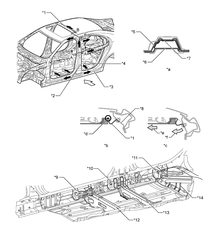
Text in Illustration *1 Roof Reinforcement *2 Center Body Pillar *3 Rocker Reinforcement *4 Floor Crossmember *5 Center Body Pillar Reinforcement Upper *6 Belt Anchor to Center Pillar Reinforcement *7 Center Body Pillar Reinforcement Inner *8 Roof Side Rail Sub-assembly Inner *9 Rocker Panel Reinforcement No. 6 *10 Rocker Panel Reinforcement No. 2 *11 Rocker Panel Reinforcement Outer *12 Front Floor Crossmember *13 Front Floor Cross Side Member *14 Center Floor Pan Front *a A - A Cross Section *b B - B Cross Section (Before Collision) *c B - B Cross Section (After Collision) *d Pin Joint *e Axial Impact *f Deform Side Impact Energy Dissipate
-
Energy absorbing pads (door trim pad lower) are used inside the doors to dampen the impact energy of a side collision. In addition, seat pipes are provided in the seat cushion frames and transmission cover are added above the floor tunnel so that the seats can be utilized as structural materials to minimize the body deformation during a side collision.
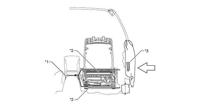
Text in Illustration *1 Transmission Cover *2 Seat Pipe *3 Door Trim Pad Lower - - Side Impact Energy Transferred Side Impact Energy -
A head impact protection structure is used. With this type of construction, if the occupant's head hits against the roof side rail or pillar due to a collision, the inner panels of the roof side rail, roof area and pillar collapse to help reduce the impact.
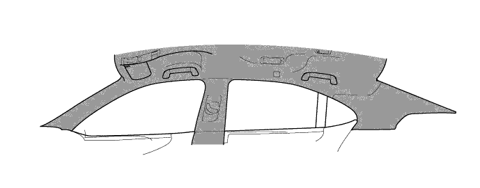
Text in Illustration 
Head Impact Protection Structure - -
-
-
-
Roof Crush Resistance
-
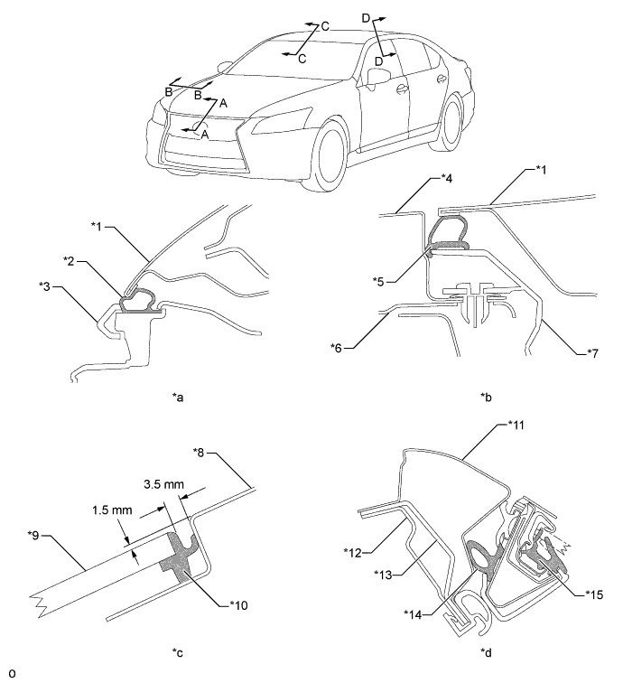
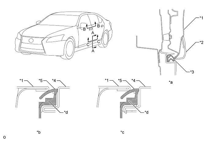
High-tensile strength sheet steel is used for the windshield header, front body pillar, roof side rail and center body pillar portions, thus ensuring a high level of roof strength through strengthening processes such as sheet thickness optimization. As a result, passenger protection when the vehicle is overturned is secured.
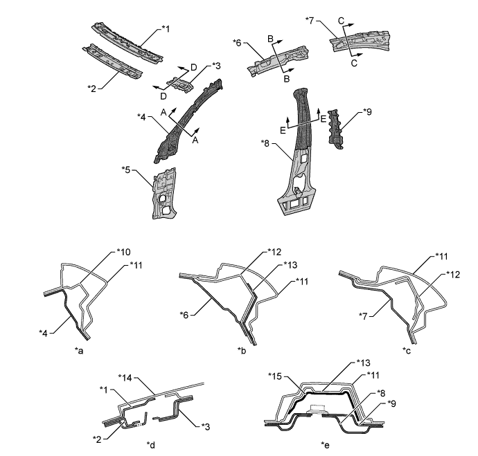
Text in Illustration *1 Windshield Header Panel Outer *2 Windshield Header Panel Inner *3 Front Body Pillar Reinforcement Upper Inner *4 Front Body Pillar Inner *5 Cowl Side Panel *6 Roof Side Rail Inner *7 Roof Side Rail Inner No. 2 *8 Center Body Pillar Inner *9 Belt Anchor to Center Pillar Reinforcement *10 Front Body Pillar Reinforcement Upper Outer *11 Side Panel Outer *12 Roof Side Rail Outer *13 Center Body Pillar Reinforcement Upper *14 Roof Panel *15 Center Body Pillar Reinforcement Inner - - *a A - A Cross Section *b B - B Cross Section *c C - C Cross Section *d D - D Cross Section *e E - E Cross Section - - 
Ultra High-tensile Strength Sheet Steel (980 MPa Class) High-tensile Strength Sheet Steel (590 MPa Class) 
High-tensile Strength Sheet Steel (440 MPa Class) - -
-
-
Lessening Pedestrian Head Injury
-
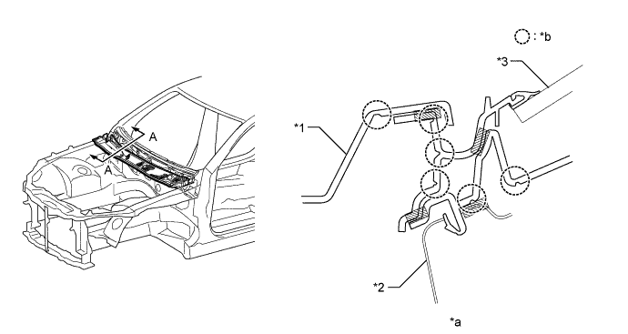
In the case of a collision with a pedestrian, pedestrian injury reduction is taken into consideration by the use of pedestrian injury reduction body. An impact absorbing body structure is used on the periphery of the hood and cowl top, thus achieving a body structure which reduces impact to the pedestrian's head, etc.
-
The hood panel inner has a safety wave construction with shelves. The beads that are provided at optimal heights that suit the areas enhance the energy absorption rate, thus pedestrian protection performance has been ensured during a collision (A - A and B - B cross sections).
-
Hood panel reinforcement has been allocated optimally in the front and rear. When an impact is received from a pedestrian during a collision, this construction dissipates that impact into a wide area. Thus, pedestrian protection performance has been ensured (C - C and D - D cross sections).
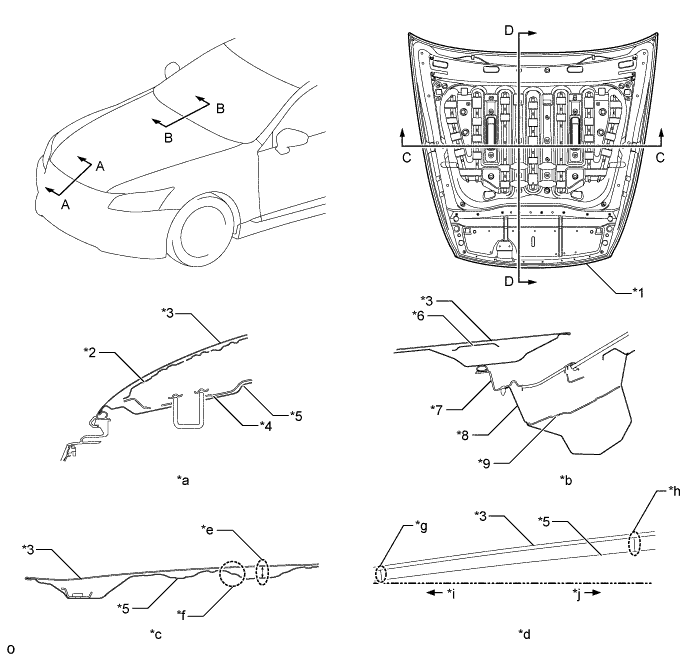
Text in Illustration *1 Hood Sub-assembly *2 Hood Panel Reinforcement *3 Hood Panel *4 Hood Lock Hook Reinforcement *5 Hood Panel Inner *6 Hood Inner Panel Reinforcement *7 Cowl Top Ventilator Louver Sub-assembly *8 Cowl Top Panel Inner *9 Wiper Motor Mounting Bracket No. 1 - - *a A - A Cross Section *b B - B Cross Section *c C - C Cross Section *d D - D Cross Section *e Bead Height *f Shelf *g Low Bead *h High Bead *i Child Head Form Zone *j Adult Head Form Zone -
Energy absorbing brackets (fender apron gusset) are used in the joint portion of the front fender. Thus, a certain deformation stroke in the event of a head form collision has been ensured, reducing the impact.
Text in Illustration *1 Fender Apron Gusset *2 Front Fender Panel *3 Front Apron To Cowl Side Member Upper - - *a A - A Cross Section *b Head Form Impact - - -
Both body rigidity and energy absorption stroke have been achieved by optimizing the shape at the back of the cowl and providing reinforcements. Thus, pedestrian protection performance has been ensured.
Text in Illustration *1 Hood Sub-assembly *2 Cowl Top Ventilator Louver Sub-assembly *3 Cowl Top Panel Inner *4 Windshield Glass *a A - A Cross Section *b Head Form (Before Collision) *c Head Form (After Collision) *d Deformation Zone *e Cowl Rear Wall - - -
Thin-walled portion to reduce deformation impact are provided at the area where the cowl top ventilator louver (which has a relatively high rigidity) and the cowl top ventilator louver protector are joined. This makes the overall rigidity of the cowl louver more uniform, and ensures the proper energy absorption stroke.
Text in Illustration *1 Cowl Top Ventilator Louver Protector *2 Cowl Top Ventilator Louver *3 Windshield Glass - - *a A - A Cross Section *b Thin-walled Portion (Deformation Point)
-
-
-
Lessening Pedestrian Leg Injury
-
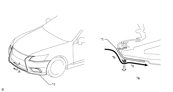
A pedestrian injury reduction body is used in consideration of reducing injury of a pedestrian in the case of a collision with a pedestrian. The impact absorbing structure is used on the periphery of the front bumper, thus achieving a body structure which reduce impact toward a pedestrian's leg, etc.
-
By optimizing the shape, foam density and location of the front bumper energy absorber and front bumper absorber lower, damage to the legs of pedestrians in the event of a collision has been lessened.
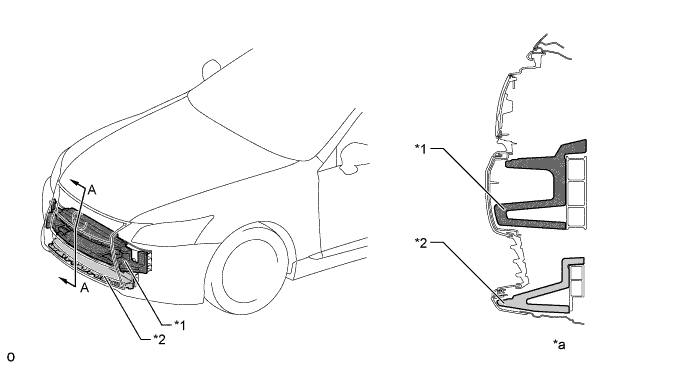
Text in Illustration *1 Front Bumper Energy Absorber *2 Front Bumper Absorber Lower *a A - A Cross Section - -
-
-
-
Aerodynamics
-
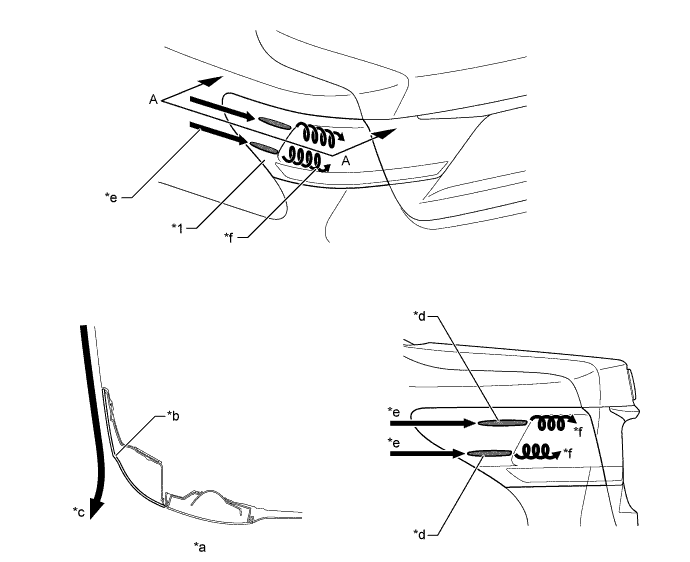
A gap is provided for the front fender liner. As a result, airflow in the wheelhouse is led along the tires to make the airflow in the wheelhouse smooth. In addition, the gap is located in the outer side of the vehicle to allow the airflow exiting from the wheelhouse to follow the airflow moving past the side of bumper. As a result, turbulence around the tires has been reduced to achieve excellent operation stability.
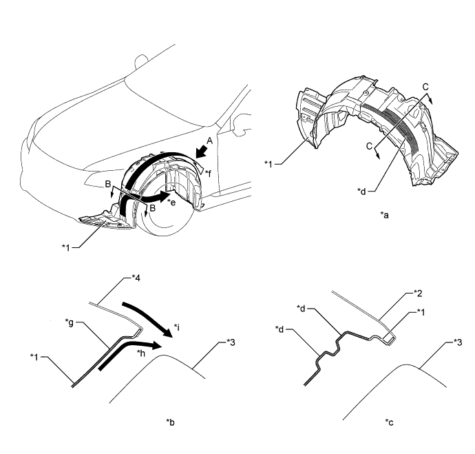
Text in Illustration *1 Front Fender Liner *2 Front Fender Panel *3 Tire *4 Front Bumper Cover *a View from A *b B - B Cross Section *c C - C Cross Section *d Groove (Gap) Structure *e Airflow Exiting from Wheelhouse *f Airflow Passing along Tire *g Gap Located in Outer Side of Vehicle *h Airflow in Wheelhouse *i Airflow Moving Past Side of Bumper - - -
The lower end of the front bumper cover has been set low to adjust the volume of air flowing to the under floor. As a result, lifting force has been suppressed, thus ensuring superior maneuver stability.
-
The front bumper cover is given a design which allows air to flow smoothly past the side of the bumper and which allows airflow to flow away from the bumper end of the wheel arch, thus reducing air resistance.
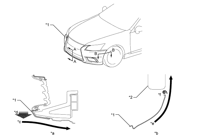
Text in Illustration *1 Front Bumper Cover *2 Tire *a A - A Cross Section *b B - B Cross Section *c Airflow toward Underfloor *d Lower End Positioned Down *e Smooth Flow of Air Past Side of Bumper *f Air Flowing away from End of Bumper Cover -
The shape of the bumper cover lower end is designed to guide airflow entering the underside of the front bumper cover away from and then back to the front bumper cover. Flowing the air in this manner causes strong negative pressure which pushes the vehicle body against the road surface. As a result, the tires are pushed against the road surface and contact is increased, thus achieving excellent operation stability.
Text in Illustration *1 Front Bumper Cover - - *a A - A Cross Section *b Air Flowing Away from Front Bumper Cover *c Airflow Returning to Front Bumper Cover - - Airflow Strong Negative Pressure -
An aero stabilizing fin is provided on the front door front lower frame cover upper and a type of aerodynamic technology known as a vortex generator is used for the fin. Small vortexes are purposely generated in airflow to push the vehicle from the left and right sides, thus achieving excellent operation stability.
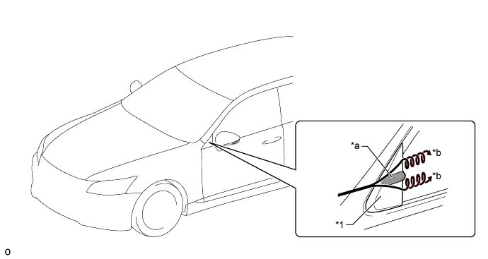
Text in Illustration *1 Front Door Front Lower Frame Cover Upper - - *a Aero Stabilizing Fin *b Generated Vortices Airflow - - -
An air-kick shape is provided on the lens surface of the rear combination light assembly. The air-kick shape cuts and sends airflow rearward to suppress vortices, and air resistance is reduced by airflow adjustment which smooth the airflow.
-
An aero stabilizing fin is provided on the lens surface of the rear combination light assembly and a type of aerodynamic technology known as a vortex generator is used for the fin. Small vortexes are purposely generated in airflow to push the vehicle from the left and right sides, thus achieving excellent operation stability.
Text in Illustration *1 Rear Combination Light Assembly - - *a A - A Cross Section *b Air-kick Shape *c Cut and Blown Air *d Aero Stabilizing Fin *e Airflow *f Generated Vortices -
Various types of airflow routing parts that control airflow are provided under the floor, and an undercover is provided to make the under floor area flat in order to ensure excellent aerodynamic performance. Some of the undercovers are made of aluminum and are provided with a sound absorption material to improve quietness, fuel economy, and ensure driving stability.
-
An aero fin which adjusts airflow is located on the engine under cover No. 1, front fender main seal and floor under cover No. 1 to smooth the flow of air which enters at the front of the vehicle and flows under the floor. Smooth airflow in the lower surface of the vehicle enhances the speed of airflow and a low pressure region is created between the vehicle and the road surface (Venturi effect). This low pressure region attracts the vehicle to the road surface, thus causing down force. Thus, superior straight-line stability has been achieved.
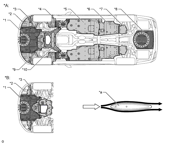
Text in Illustration *A 2WD Models *B AWD Models *1 Engine Under Cover No. 1 *2 Front Fender Liner *3 Front Wheel Opening Extension Pad *4 Front Fender Main Seal *5 Front Floor Cover *6 Rear Floor Side Member Cover *7 Differential Support Protector No. 1 *8 Floor Under Cover No. 1 *9 Front Suspension Member Protector LWR *10 Engine Under Cover No. 2 *a Aero Fin - - Airflow High-speed Airflow
-
-
-
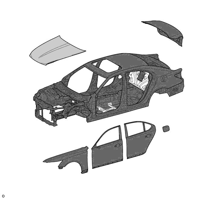
CONSTRUCTION
-
Lightweight and Highly Rigid Body
-
High-tensile strength steel and ultra high-tensile strength steel are used in order to achieve excellent body rigidity and a lightweight body. Ultra high-tensile strength steel has approximately 1.3 times the strength of conventional high-tensile strength steel.
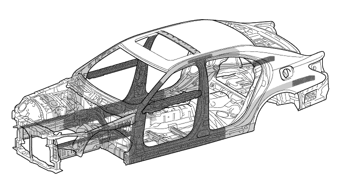
Text in Illustration Ultra High-tensile Strength Steel High-tensile Strength Steel -
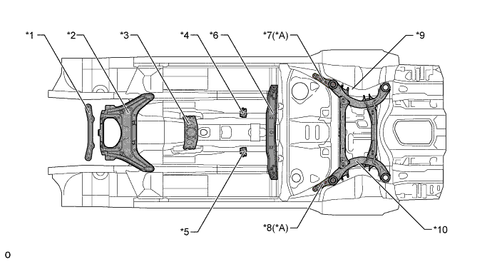
The hood sub-assembly, front bumper mounting reinforce sub-assembly, front bumper reinforcement, front suspension crossmember lower, frame side rail rear, front suspension crossmember sub-assembly (2WD models) / front frame assembly (AWD models), rear bumper arm support reinforcement and a part of rear bumper reinforcement No. 1 are made of aluminum steel for weight reduction. Compared to steel, the use of aluminum has realized a weight reduction of 30% at the front suspension crossmember sub-assembly (2WD models) / front frame assembly (AWD models) and 45% at the hood sub-assembly.
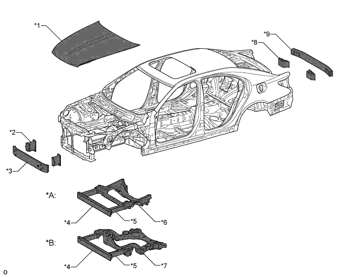
Text in Illustration *A 2WD Models *B AWD Models *1 Hood Sub-assembly *2 Front Bumper Mounting Reinforce Sub-assembly *3 Front Bumper Reinforcement *4 Front Suspension Crossmember Lower *5 Frame Side Rail Rear *6 Front Suspension Crossmember Sub-assembly *7 Front Frame Assembly *8 Rear Bumper Arm Support Reinforcement *9 Rear Bumper Reinforcement No. 1 - - Aluminum Steel - - -
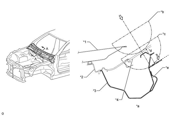
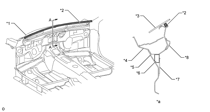
A cowl top inner reinforcement has been added to the cowl panel sub-assembly. A dash panel to cowl brace and the toe board RH reinforcement and the toe board LH reinforcement have been added to the dash panel sub-assembly. Further, the floor crossmember sub-assembly No. 3 have been reinforced. These measures have helped to improve the torsional rigidity of the body and ensure driving stability.
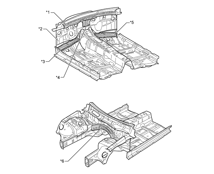
Text in Illustration *1 Cowl Top Inner Reinforcement *2 Dash Panel Sub-assembly *3 Toe Board LH Reinforcement *4 Dash Panel to Cowl Brace *5 Toe Board RH Reinforcement *6 Floor Crossmember Sub-assembly No. 3 -
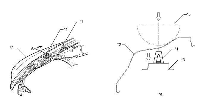
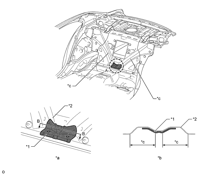
In addition to conventional spot welding, adhesive agent has been added in the windshield header portion and body lower back portion. As a result, connecting rigidity has been enhanced to achieve excellent ride comfort quality and operation stability.
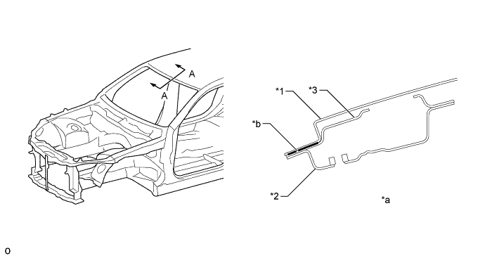
Text in Illustration *1 Roof Panel *2 Windshield Header Panel Inner *3 Windshield Header Panel Outer - - *a A - A Cross Section *b Adhesive Agent 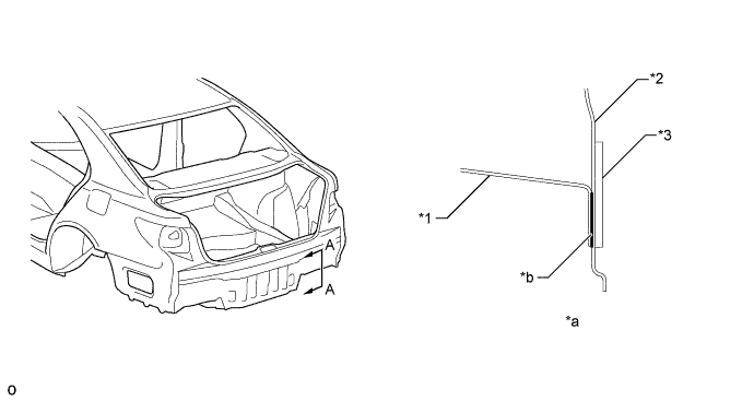
Text in Illustration *1 Rear Floor to Outer Extension Sub-assembly *2 Body Lower Back Panel *3 Body Lower Back Reinforcement No. 2 - - *a A - A Cross Section *b Adhesive Agent -
Many spot welding points are provided on the dash panel and cowl top panel inner, thus ensuring superior maneuvering stability by enhancing the connecting rigidity of the panels.
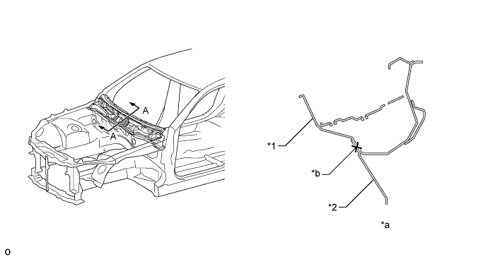
Text in Illustration *1 Cowl Top Panel Inner *2 Dash Panel *a A - A Cross Section *b Spot Welding Point -
Laser Screw Welding (LSW) has been used between spot welding points in the door opening portion, thus achieving excellent ride comfort quality.
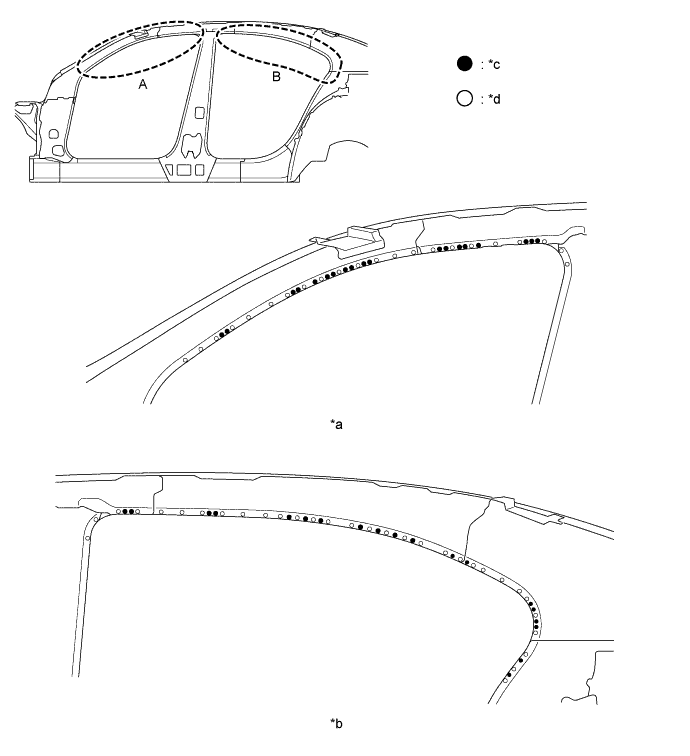
Text in Illustration *a Section A *b Section B *c Laser Screw Welding *d Spot Welding -
The room partition panel sub-assembly is made of differential thickness bonded steel and is laser welded to effectively improve its torsional rigidity while minimizing the weight increase.
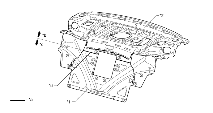
Text in Illustration *1 Room Partition Panel Sub-assembly *2 Upper Back Panel Sub-assembly *a Laser Welded Areas *b Thin *c Thick *d Boundary -
Strengthened panel (room partition panel reinforcement) is provided at the base of the V groove in the room partition panel sub-assembly to restrict deformation caused by vertical direction force which is transmitted from the left and right suspensions. As a result, excellent operation stability (steering response and rear wheel grip feel) has been achieved.
Text in Illustration *1 Room Partition Panel Reinforcement *2 Room Partition Panel Sub-assembly *a Section A *b B - B Cross Section *c V Groove - - -
A large-size engine rear mounting member is provided on 2WD models. The number of bolt joints has been increased (to 6 bolts) to strengthen the body framework, thus achieving excellent steering response.
-
A large-size front seat mounting bracket outside LH/RH and a large-size front floor brace sub-assembly center are provided to strengthen the body framework, thus achieving excellent ride comfort.
-
A front floor brace sub-assembly center and rear suspension member sub-assembly are is provided. Also, a rear suspension member stopper lower LH/RH that joins the front mounting area of the rear suspension member sub-assembly and a rear floor sidemember front are provided on F SPORT. These parts improve the rigidity of the areas where the suspension is mounted and also ensure driving stability.
-
On 2WD models, the engine under cover No. 2 is made of aluminum to improve body rigidity.
-
On AWD models, the aluminum front suspension member protector LWR is arranged so it connects with the front cross member sub-assembly.
Text in Illustration (2WD Models) *A F SPORT - - *1 Steering Rack Housing Bracket No. 1 *2 Engine Under Cover No. 2 *3 Engine Rear Mounting Member *4 Front Seat Mounting Bracket Outside LH *5 Front Seat Mounting Bracket Outside RH *6 Front Floor Brace Sub-assembly Center *7 Rear Suspension Member Stopper Lower LH *8 Rear Suspension Member Stopper Lower RH *9 Rear Floor Side Member Front *10 Rear Suspension Member Sub-assembly 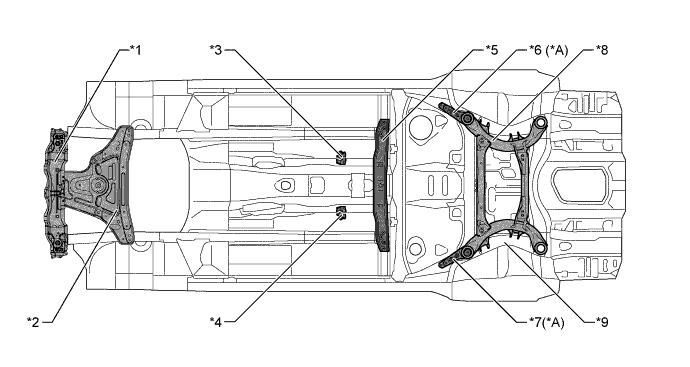
Text in Illustration (AWD Models) *A F SPORT - - *1 Front Cross Member Sub-assembly *2 Front Suspension Member Protector LWR *3 Front Seat Mounting Bracket Outside LH *4 Front Seat Mounting Bracket Outside RH *5 Front Floor Brace Sub-assembly Center *6 Rear Suspension Member Stopper Lower LH *7 Rear Suspension Member Stopper Lower RH *9 Rear Suspension Member Sub-assembly *9 Rear Floor Side Member Front - - -
A reinforcement panel (body lower back reinforcement No. 2) has been added to the joint section of the rear floor side member sub-assembly and the rear bumper reinforcement No. 1, thus restricting the twist deformation of the body caused by vertical direction force transmitted from the left and right suspensions. Also, the thickness of the washer of the bolt which connects the rear bumper reinforcement No. 1 has been increased to lessen shear deformation and to enhance the rigidity of the connection between the body and the rear bumper reinforcement No. 1. As a result, excellent operation stability (steering response and rear wheel grip feel) has been achieved.
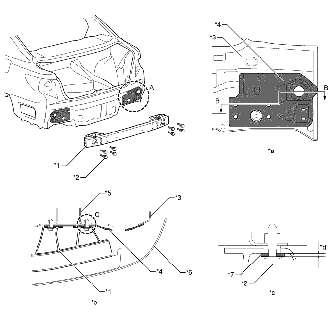
Text in Illustration *1 Rear Bumper Reinforcement No. 1 *2 Rear Bumper Reinforcement No. 1 Joint Bolt *3 Body Lower Back Panel *4 Body Lower Back Reinforcement No. 2 *5 Rear Floor Side Member Sub-assembly *6 Rear Bumper Cover *7 Washer - - *a Section A *b B - B Cross Section *c Section C *d Washer Thickness
-
-
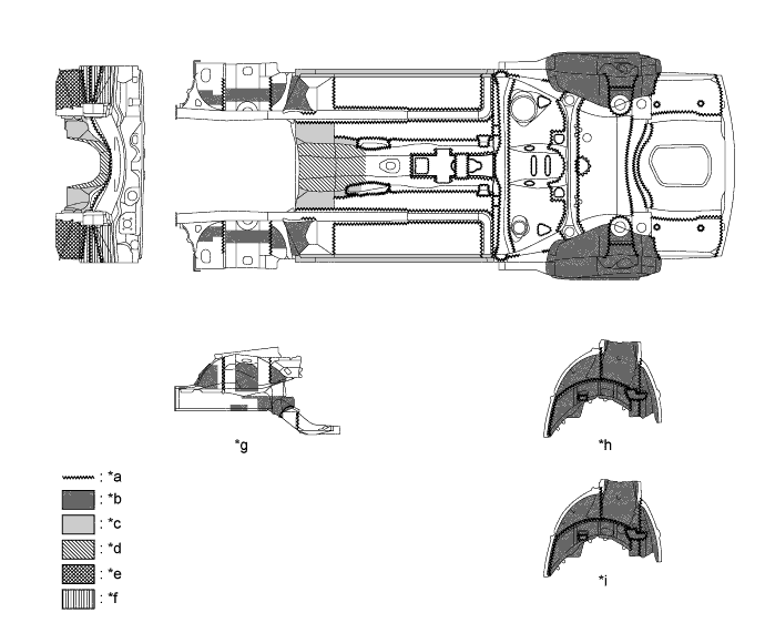
Anti-corrosion Sheet Steel
-
Anti-corrosion sheet and Aluminum Steel are used as in the following illustration:
Text in Illustration Aluminum Steel Anti-corrosion Sheet Steel
-
-
Anti-chipping Application and Rust-resistant Performance
-
Polyvinyl Chloride (PVC) coating is applied to the wheelhousings, and other parts that are located where they are susceptible to stone chipping damage, improving the rust-resistance of these areas.
Text in Illustration (2WD Models) *a Edge Seal *b Under Coating Area (Heavy Portion (Wet)) *c Under Coating Area (General Portion) *d Under Coating Area (Thin Portion) *e Under Coating Area (Heavy Portion) *f Under Coating Area (General Portion (Wet)) *g Apron *h Rear Right Hand Wheelhouse *i Rear Left Hand Wheelhouse - - 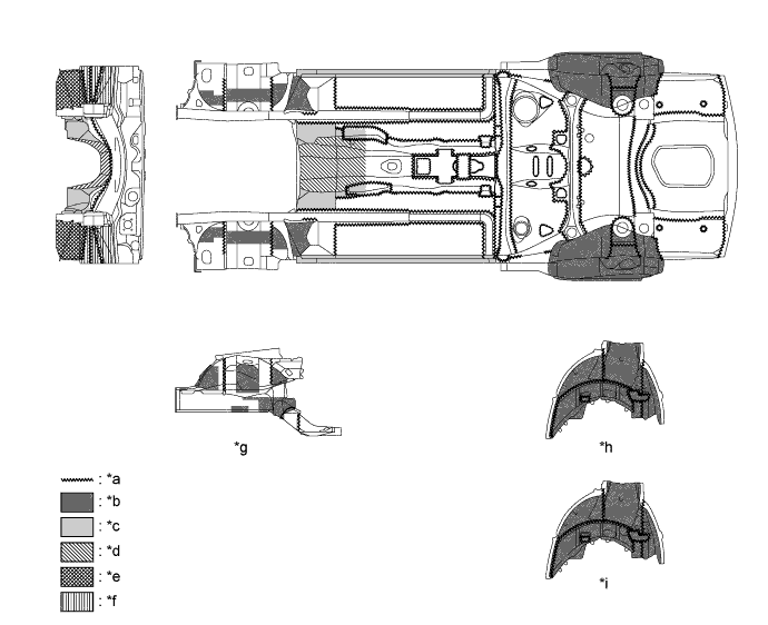
Text in Illustration (AWD Models) *a Edge Seal *b Under Coating Area (Heavy Portion (Wet)) *c Under Coating Area (General Portion) *d Under Coating Area (Thin Portion) *e Under Coating Area (Heavy Portion) *f Under Coating Area (General Portion (Wet)) *g Apron *h Rear Right Hand Wheelhouse *i Rear Left Hand Wheelhouse - - -
Wax is applied to edge of the door lower portion, door hinge and fuel filler lid hinge to improve rust-resistant performance. Sealer is applied to hemmed portions of the door panels and luggage door.
Text in Illustration *1 Hood Hinge Assembly *2 Front Door Hinge Assembly Lower *3 Rear Door Hinge Assembly Lower *4 Hood Panel *5 Hood Panel Inner *6 Front Door Panel Inside *7 Front Door Outside Panel *8 Rear Door Inside Panel *9 Rear Door Panel Outer - - *a A - A Cross Section *b B - B Cross Section *c C - C Cross Section *d Wax
-
-
Sound Absorbing and Vibration Damping Materials
-
A large-size dash panel insulator assembly, dash panel insulator outer, hood insulator, and engine under cover silencer (engine under cover silencer No. 5 and engine under cover silencer rear RH) are used to reduce engine and road noise to improve quietness inside the passenger compartment.
-
Sound absorption materials are used in the engine under cover No. 1, front floor cover, and front floor heat insulator sub-assembly No. 2 to ensure quieter operation during idling and all driving conditions.
-
In order to minimize grit, water and road noises, the polyethylene plastic front fender liners, which are optimally covered with Polypropylene (PP) and polyester felt, are fitted inside the front wheelhouses. For the rear wheelhouses, Styrene Butadiene Rubber (SBR) and Polyethylene Terephthalate (PET) plastic rear wheelhouse liner, which are optimally covered with PET felt, are fitted.
-
A material having high sound-shielding property is used for the intermediate film of the laminated glass of the windshield glass to reduce wind noise.
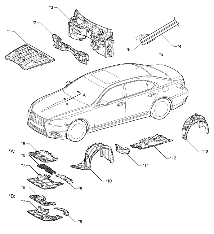
Text in Illustration *A 2WD Models *B AWD Models *1 Hood Insulator *2 Dash Panel Insulator Outer *3 Dash Panel Insulator Assembly *4 Windshield Glass *5 Engine Under Cover No. 4 *6 Engine Under Cover Silencer No. 5 *7 Engine Under Cover No. 1 *8 Engine Under Cover Silencer Rear RH *9 Engine Under Cover Silencer Rear *10 Front Fender Liner *11 Front Floor Heat Insulator Sub-assembly No. 2 *12 Front Floor Cover *13 Rear Wheelhouse Liner - - *a A - A Cross Section *b Film -
Urethane is provided on the wide area of the dash panel insulator assembly and the clearance of each hole is filled to reduce the engine noise and road noise entering the cabin, thus achieving excellent quietness.
-
Sound absorption felt is provided on the dash panel insulator pad No. 3 and the dash panel insulator pad No. 2 to reduce the engine noise and road noise entering the cabin, thus achieving excellent quietness.
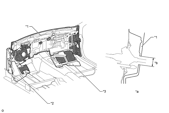
Text in Illustration *1 Dash Panel Insulator Assembly *2 Dash Panel Insulator Pad No. 3 *3 Dash Panel Insulator Pad No. 2 - - *a A - A Cross Section *b Clearance Filling Structure Urethane - - -
Noise absorbing material is provided for the front fender liner, thus reducing sound created by flying sand, flying water, engine noise and road noise.
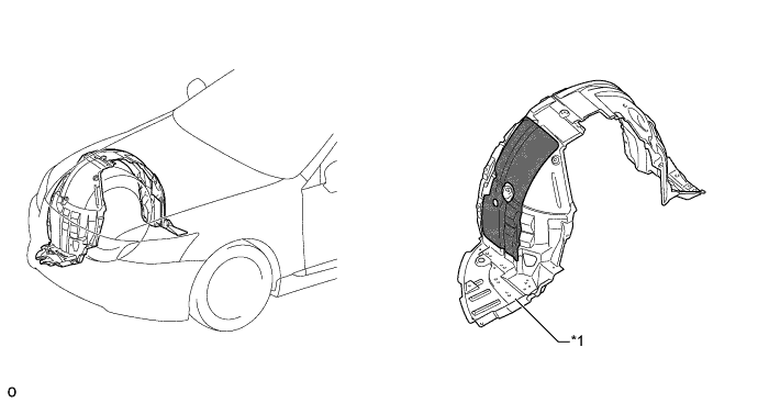
Text in Illustration *1 Front Fender Liner - - Noise Absorbing Material - - -
Noise absorbing material is provided for the rear wheelhouse liner, thus reducing sound created by flying sand, flying water and road noise.
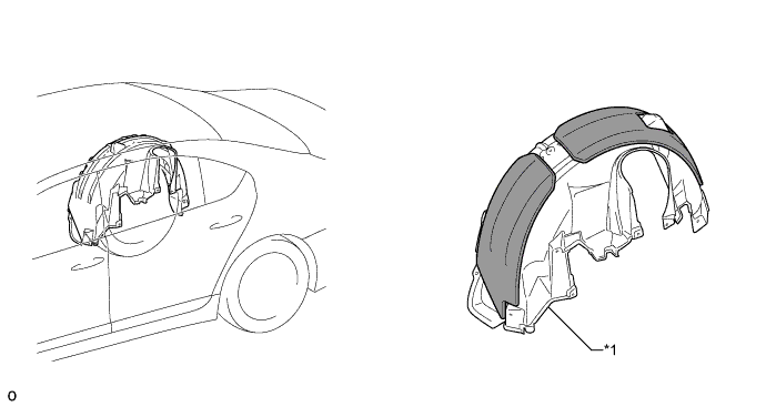
Text in Illustration *1 Rear Wheelhouse Liner - - Noise Absorbing Material - - -
Sponge (instrument panel cushion No. 1) is provided on the upper surface of the cowl panel sub-assembly to suppress the engine noise entering the cabin, thus achieving excellent quietness.
Text in Illustration *1 Cowl Panel Sub-assembly *2 Instrument Panel Cushion No. 1 *3 Windshield Glass *4 Cowl Top Panel Inner *5 Dash Panel *6 Pillar Pad No. 5 *7 Dash Panel to Cowl Brace *8 Cowl Top Inner Reinforcement *a A - A Cross Section - - -
To reduce the amount of road noise, engine noise, and droning sound that enters the cabin, the floor panel is coated with a floor silencer.
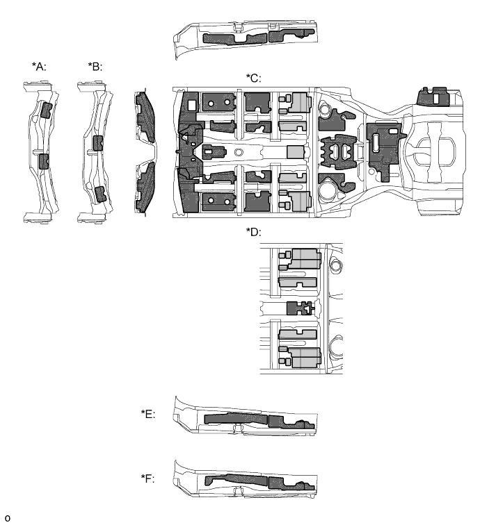
Text in Illustration *A RHD Models *B LHD Models *C Standard Body Models *D Long Body Models *E 2WD Models *F AWD Models Asphalt Sheet Damping Material -
Sound insulation materials are used in the body frame profile, thus dampening the various noises which intrude from the outside of the vehicle to the inside of the cabin.
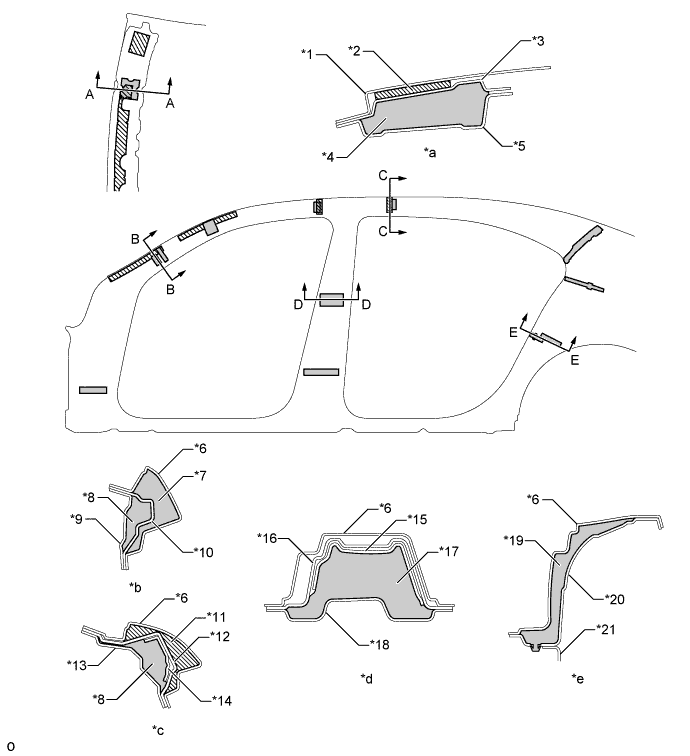
Text in Illustration *1 Roof Panel *2 Roof Silencer Pad No. 1 *3 Windshield Header Panel Outer *4 Roof Silencer Pad Rear *5 Windshield Header Panel Inner *6 Side Panel Outer *7 Pillar Pad No. 2 *8 Pillar Pad No. 1 LH *9 Front Body Pillar Inner *10 Front Body Pillar Reinforcement Upper Outer *11 Pillar Pad No. 1 RH *12 Roof Side Rail Outer *13 Roof Side Rail Inner No. 2 *14 Roof Side Rail Outer No. 2 *15 Center Body Pillar Reinforcement Inner *16 Center Body Pillar Reinforcement Upper *17 Pillar Pad No. 4 *18 Center Body Pillar Inner *19 Quarter Wheelhouse Seal *20 Quarter Wheelhouse Panel Outer *21 Quarter Wheelhouse Gusset Front - - *a A - A Cross Section *b B - B Cross Section *c C - C Cross Section *d D - D Cross Section *e E - E Cross Section - - Foam Materials 
Damping Materials -
All the locations of sound insulation and absorption materials in the cabin have been optimized. thus creating a quiet drive.
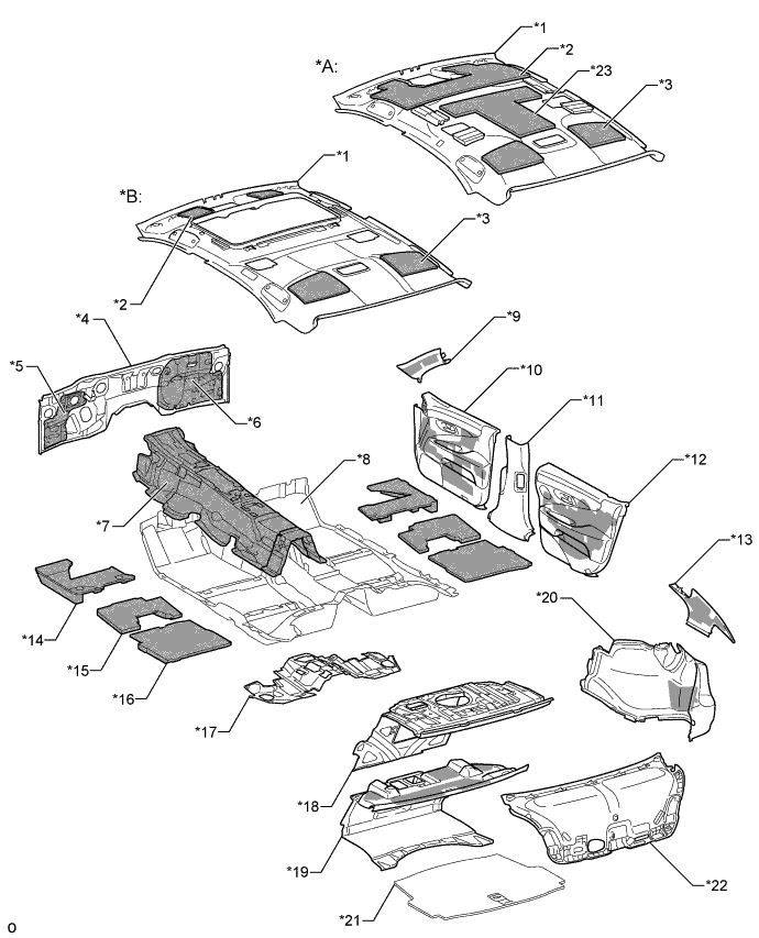
Text in Illustration *A Models with Normal Roof *B Models with Sliding Roof System *1 Roof Headlining Assembly *2 Roof Silencer Pad Front *3 Roof Silencer Pad *4 Dash Panel Sub-assembly *5 Dash Panel Insulator Assembly No. 3 *6 Dash Panel Insulator Assembly No. 2 *7 Center Floor Silencer Sheet *8 Front Floor Carpet Assembly Front *9 Front Pillar Garnish *10 Front Door Trim Board Sub-assembly *11 Center Pillar Garnish Lower *12 Rear Door Trim Board Sub-assembly *13 Roof Side Garnish Inner *14 Front Floor Silencer Pad *15 Center Floor Silencer Pad Rear *16 Rear Floor Silencer Pad No. 1 *17 Room Partition Pad No. 3 *18 Room Partition Panel Sub-assembly *19 Luggage Compartment Trim Cover Front *20 Luggage Compartment Trim Cover Assembly *21 Luggage Compartment Mat Sub-assembly *22 Back Door Trim Cover *23 Roof Silencer Pad Center - - -
Sound absorption material is provided on the rear door service hole cover to suppress noise entering the cabin, thus achieving excellent NV performance.

Text in Illustration *A Models without Rear RH Curtain Sub-assembly *B Models with Rear RH Curtain Sub-assembly *1 Rear Door Panel Sub-assembly *2 Rear Door Service Hole Cover -
The radiator grille is designed to prevent airflow from hitting the inside of the fin, thus suppressing cavity noise (noise which is generated by air flowing through the cavities).
-
A saw shape is used on the underside of the fin on the radiator grille lower to suppress cavity noise by disrupting the airflow.
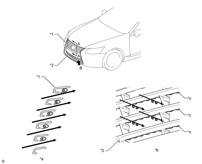
Text in Illustration *1 Radiator Grille *2 Radiator Grille Lower No. 1 *a A - A Cross Section *b View from B *c Saw Shape - - Airflow - - -
The air turbulence has been eliminated through the optimization of the shape of the radiator grille protector (A - A cross section) and the use of the hood to front fender seal (B - B cross section).
-
Bifacial molding is used around the windshield glass to minimize the offset and the parting width between the windshield glass and the roof panel. This reduces air turbulence and wind noise (C - C cross section).
-
The front door weatherstrip is made of a material that suffers minimal deterioration in order to reduce aging deterioration. A lip has been added to the base surface of the glass run to reduce wind noise (D - D cross section).
Text in Illustration *1 Hood Panel *2 Radiator Grille Protector *3 Radiator Grille Molding *4 Front Fender Panel *5 Hood to Front Fender Seal *6 Front Fender Side Panel Lower *7 Front Fender Protector Upper *8 Roof Panel *9 Windshield Glass *10 Windshield Molding Outside *11 Side Panel Outer *12 Front Body Pillar Inner *13 Front Body Pillar Reinforcement Upper Outer *14 Front Door Weatherstrip *15 Lip - - *a A - A Cross Section *b B - B Cross Section *c C - C Cross Section *d D - D Cross Section -
A front fender side panel protector is used between the front fender panel and the side panel outer to prevent air from blowing through. In addition, a front door weatherstrip No. 3 is used between the front fender panel and the front door outside panel to eliminate air turbulence. (A - A cross section).
-
Rear door weatherstrip No. 2 is employed between the front door panel outer and rear door panel outer to eliminate air turbulence (B -B cross sections).
-
A cap is provided at the top end of the division bar to block the airflow and reduce wind noise (C - C cross section).
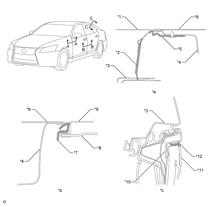
Text in Illustration *1 Front Fender Panel *2 Front Fender Side Panel Protector *3 Side Panel Outer *4 Front Door Panel Inside *5 Front Door Weatherstrip No. 3 *6 Front Door Outside Panel *7 Rear Door Weatherstrip No. 2 *8 Rear Door Inside Panel *9 Rear Door Panel Outer *10 Rear Door Belt Molding *11 Division Bar *12 Cap *a A - A Cross Section *b B - B Cross Section *c C - C Cross Section - - -
A fin shape is used at the end of the roof drip side finish molding center. As a result, airflow moving rearward along the windshield glass has been made smooth to suppress wind noise. Also, the width of lower portion of the front body pillar (side panel outer) has been increased. As a result, flow which does not move rearward and moves sideways can flow smoothly over the front body pillar, thus suppressing wind noise.
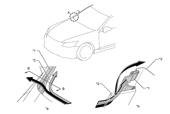
Text in Illustration *1 Roof Drip Side Finish Molding Center *2 Windshield Glass *3 Side Panel Outer - - *a Section A *b A - A Cross Section (View from Cabin) 
Airflow Moving Rearward Airflow Moving Sideways -
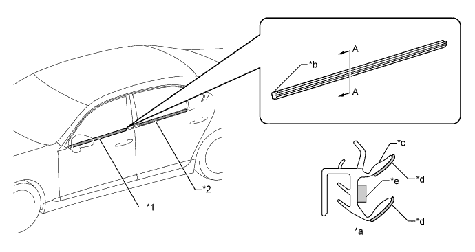
A front door weatherstrip No. 3 is used for the door under seal. 2 protrusions are provided below the belt line of the rear weatherstrip. These features prevent the door from fluttering noisily while it is being closed and instead give it a solid and resounding thump.
Text in Illustration *1 Front Door Outside Panel *2 Front Door Molding Sub-assembly Outside *3 Front Door Weatherstrip No. 3 *4 Rear Door Panel Outer *5 Rear Door Weatherstrip No. 2 - - *a A - A Cross Section *b B - B Cross Section *c C - C Cross Section *d Protrusion -
Caulking sponge at the front end and rear end of the front door glass weatherstrip inner and rear door glass weatherstrip inner has been optimized, electrostatic flocking has been made finer and acoustic material is placed between the lips, thus reducing wind noise and suppressing noise entering the cabin.
Text in Illustration *1 Front Door Glass Weatherstrip Inner *2 Rear Door Glass Weatherstrip Inner *a A - A Cross Section *b Caulking Sponge *c Lip *d Electrostatic Flocking *e Acoustic Material - -
-
-
Parts with Low Repair Cost
-
The parts (the front bumper reinforcement, crush boxes (front bumper mounting reinforce sub-assembly), and the radiator support sub-assembly) located forward of the front ends of the front side member sub-assembly inner are bolted on to reduce the repair cost of the front end of the vehicle in case of a minor collision.
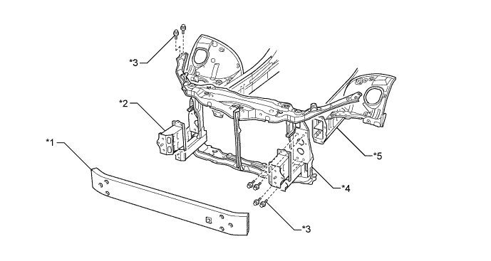
Text in Illustration *1 Front Bumper Reinforcement *2 Front Bumper Mounting Reinforce Sub-assembly *3 Bolt *4 Radiator Support Sub-assembly *5 Front Side Member Sub-assembly Inner - - -
In the rear bumper, the rear bumper energy absorber is provided. The cross section of the bumper arms has been formed into a crushable shape that provides efficient impact absorption. These features help reduce the impact that acts on the body and reduce the repair cost in case of a minor collision.
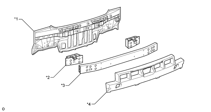
Text in Illustration *1 Body Lower Back Panel *2 Rear Bumper Arm Support Reinforcement *3 Rear Bumper Reinforcement *4 Rear Bumper Energy Absorber
-
-