ENTRY AND START SYSTEM DETAILS
-
FUNCTION OF MAIN COMPONENTS
-
The main components of the entry and start system have the following functions:
Component Function Engine Switch (Push Start Switch)
- Transponder Key Amplifier
-
Transmits the engine switch signal to the main body ECU.
-
Receives the ID code and transmits it to the certification ECU when the electrical key transmitter sub-assembly battery is too weak to respond to the tuner based on the indoor electrical key oscillator and No. 2 electrical key oscillator.
Electrical Key Transmitter Sub-assembly
-
2 types of electrical key transmitter sub-assemblies are used: electrical key transmitter sub-assembly (electrical key) and electrical key transmitter subassembly (card key)*1.
-
The electrical key transmitter sub-assembly (electronic key) consists of a mechanical key, a transmitter for the wireless door lock control, a transceiver for the entry and start system and a transponder chip for the immobiliser control.
-
The electrical key transmitter sub-assembly (card key)*1 consists of a mechanical key, a transceiver for the entry and start system and a transponder chip for the immobiliser control.
-
Receives signals from the antennas and returns the ID code to the door control receiver.
Certification ECU (Smart Key ECU Assembly)
-
Certifies the ID code received from the door control receiver and transmits the certification results to the ID code box and steering lock ECU.
-
Judges and certifies the ID code from the door control receiver.
-
Transmits the immobiliser deactivation signal to the ID code box.
-
Transmits steering unlock signals to the steering lock ECU.
Stop Light Switch Assembly Outputs the state of the brake pedal to the main body ECU. Steering Lock Actuator Assembly (Steering Lock ECU) Receives the steering lock/unlock signal from the ID code box, and activates the steering lock motor. ID Code Box (Immobiliser Code ECU) Receives the steering unlock or immobiliser unset request signals from the certification ECU, certifies them, and transmits each unset signal to the steering lock ECU or ECM. ECM
-
Receives the engine start request signal from the main body ECU, turns on the starter relay, and starts the engine.
-
Receives the signal from the ID code box and performs engine ignition and injection.
Park/Neutral Position Switch Assembly Detects the shift position and transmits a shift position signal to the main body ECU. Main Body ECU (Driver Side Junction Block)
-
Turns the power source mode off, on (ACC), on (IG), or START in accordance with the shift lever position and the state of the stop light switch assembly.
-
Controls the start function in accordance with the signals received from the switches and each ECU.
-
Transmits the key certification request signal to the certification ECU in accordance with the engine switch signal, and turns the relays on and off.
-
Receives the request signal from the certification ECU and actuates the door lock motor to unlock or lock the door.
-
Transmits the condition each door to the certification ECU.
Multiplex Network Door ECU
-
Receives the request signal from the touch sensor and transmits the request signals to the certification ECU.
-
Receives the request signal from the lock switch and transmits the request signals to the certification ECU.
Outside Door Handle Assembly Touch Sensor Detects when a person touches the inside of an outside door handle assembly. Lock Switch Transmits the door lock request signal to the multiplex network door ECU. Electrical Key Antenna Transmits the request signals. Door Electrical Key Oscillator Receives the request signal from the certification ECU and forms an actuation area around the front and rear doors. Luggage Electrical Key Switch Transmits a luggage compartment door open request signal to the certification ECU. Indoor Electrical Key Oscillator and No. 2 Indoor Electrical Key Oscillator Receives the request signal from the certification ECU and forms an actuation area inside the interior of the vehicle. Amplifier Antenna Assembly Receives the ID code from the key in the actuation area and transmits it to the door control receiver. Wireless Door Lock Buzzer Sounds as an answerback for entry lock or unlock to inform the driver.*2 No. 3 Indoor Electrical Key Oscillator Receives the request signal from the certification ECU and forms an actuation area in the luggage compartment. Electrical Key Antenna (Outside Luggage) Receives the request signal from the certification ECU and forms an actuation area around the luggage compartment. Door Control Receiver Receives the ID code from the electrical key transmitter sub-assembly in the actuation area and transmits it to the certification ECU. Combination Meter Assembly Multi-information Display When the certification ECU detects human error, it warns the driver by sounding the wireless door lock buzzer*3 and the multi buzzer in the combination meter assembly, and by illuminating a warning on the multi-information display and the master warning light in accordance with the request signal from the certification ECU. Multi Buzzer Master Warning Light
-
*1: Models with electrical key transmitter sub-assembly (card key)
-
*2: Models with wireless door lock buzzer answer back function
-
*3: Except models for China
-
-
-
OPERATING CONDITION
-
The special functions of the entry and start system only work when the electrical key transmitter sub-assembly is in the actuation area formed by the 8 electrical key oscillators.
-
The indoor electrical key oscillator and No. 2 indoor electrical key oscillator form the actuation area of the start function.
-
The No. 3 indoor electrical key oscillator forms an actuation area in the luggage compartment to prevent the electrical key transmitter sub-assembly from being confined inside the luggage compartment.
-
The door electrical key oscillators and the electrical key antenna (outside luggage) form the actuation area of the entry function.
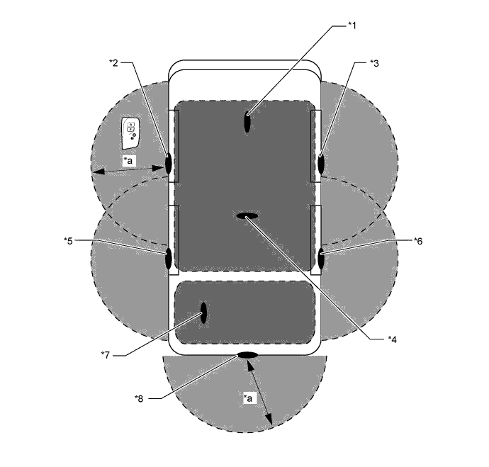
Text in Illustration *1 Indoor Electrical Key Oscillator *2 Front Door Electrical Key Oscillator LH *3 Front Door Electrical Key Oscillator RH *4 No. 2 Indoor Electrical Key Oscillator *5 Rear Door Electrical Key Oscillator LH *6 Rear Door Electrical Key Oscillator RH *7 No. 3 Indoor Electrical Key Oscillator *8 Electrical Key Antenna (Outside Luggage) *a Approx. 0.7 m to 1.0 m (2.3 ft. to 3.3 ft.) - - 
Interior Actuation Area 
Exterior Actuation Area
-
-
FUNCTION
-
Start Function
-
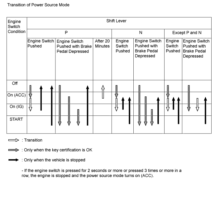
The start function has different power source modes to suit the brake pedal condition and shift lever position.
-
When a driver carrying an electrical key transmitter sub-assembly enters the vehicle while the power source mode is off and presses the engine switch without depressing the brake pedal, the power source mode turns on (ACC), causing the engine switch indicator light to illuminate amber. With each pressing of the engine switch, the power source mode switches as follows: off → on (ACC) → on (IG) → off.
-
When a driver who is carrying an electrical key transmitter sub-assembly enters the vehicle while the power source mode is off, and depresses the brake pedal while the shift lever is in P or N, the engine switch indicator light illuminates green. Pressing the engine switch with the indicator light illuminated green causes the engine to start.
-
When starting the engine with the vehicle stopped, pressing the engine switch while the shift lever is in P causes the power source mode to turn off. Pressing the engine switch when the shift lever is in any position other than P causes the mode to turn on (ACC).
-
Transition of the power source mode when the electrical key transmitter sub-assembly battery is low or the electrical key transmitter sub-assembly is not operating normally due to an electromagnetic interference is as follows:
-
The driver uses the mechanical key to unlock the door, and enters the vehicle while carrying the electrical key transmitter sub-assembly.
-
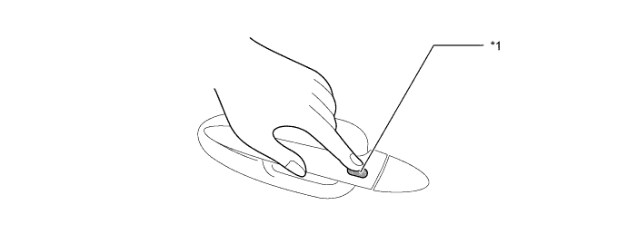
The driver places the LEXUS mark of the electrical key transmitter sub-assembly in contact with the front of the engine switch while depressing the brake pedal.
-
After the multi buzzer sounds, the driver releases the brake pedal and presses the engine switch.
-
With pressing of the engine switch, the power source mode switches as follows: off → on (ACC) → on (IG) → off.
-
-
Starting the engine when the electrical key transmitter sub-assembly battery is low or the electrical key transmitter sub-assembly is not operating normally due to an electromagnetic interference:
-
The driver uses the mechanical key to unlock the door and enters the vehicle while carrying the electrical key transmitter sub-assembly.
-
The driver places the LEXUS mark of the electrical key transmitter sub-assembly in contact with the front of the engine switch while depressing the brake pedal the shift lever is in P or N.
-
Within approximately 10 seconds after the multi buzzer sounds and the engine switch indicator light illuminates green, the driver presses the engine switch while depressing the brake pedal.
-
Pressing the engine switch starts the engine.
Tech Tips
-
Normally, the operation of the engine switch is disabled while the vehicle is being driven. However, if the engine must be stopped in an emergency while the vehicle is in motion, the driver can press the engine switch either 3 times in rapid succession or for approximately 2 seconds or more to stop the engine.
-
If no signals are transmitted to the certification ECU due to a malfunction in the stop light switch assembly or park/neutral position switch assembly, the engine does not start even if the driver presses the engine switch while depressing the brake pedal. In this case, the driver can start the engine by carrying out the following operations. Press the engine switch to turn the power source mode from off to on (ACC), press the engine switch again and hold it for 15 seconds or more.
-
The above 2 operations must be carried out only in emergency situations. Under normal conditions, the engine must not be stopped by pressing the engine switch during driving or started without depressing the brake pedal when the shift lever is in any position other than P or N.
-
-
-
-
Entry Function
-
The entry function consists of the following functions:
Function Outline Wireless Door Lock Control This function is a convenient system for locking and unlocking all the doors at a distance. Entry Illumination Operates the illuminated entry system when the electrical key transmitter sub-assembly enters the exterior actuation area of the door electrical key oscillator. Entry Unlock When a electrical key transmitter sub-assembly is located in the actuation area of any door electrical key oscillator, the door unlocks after the inside of an outside door handle assembly is touched. Entry Unlock Mode Switching Allows selection of one of the following 4 modes that can be operated with the entry unlock function:
-
Driver Door Mode
-
Adjacent Door Mode
-
Individual Door Mode
-
All Door Mode
Entry Lock When an electrical key transmitter sub-assembly is located in the actuation area of any door electrical key oscillator and the power source mode is off, the door can be locked by merely pressing the lock switch on the outside door handle assembly. Entry Luggage Compartment Door Open When an electrical key transmitter sub-assembly is in the actuation area of the electrical key antenna (outside luggage), the luggage compartment door can be opened by merely pressing the luggage electrical key switch. Window and Sliding Roof Close With the electrical key transmitter sub-assembly in the actuation area of any door electrical key oscillators, all open windows and the sliding roof are closed when the lock switch on the outside door handle assembly is pressed for 3 seconds or more. Memory Call This function operates the driving position memory system in accordance with the key ID. Key Confine Prevention
-
Prevents the confinement of the electrical key transmitter sub-assembly if the door is locked from the outside door handle assembly while the electrical key transmitter sub-assembly is still inside the vehicle.
-
If the luggage compartment door is closed while the electrical key transmitter sub-assembly is still in the luggage compartment, the warning buzzer sounds. If the electrical key transmitter subassembly is operated for 2 seconds during this period, the luggage compartment door can be opened.
Key Cancel The following electrical key transmitter sub-assembly functions can be canceled by following certain procedures:
-
Entry unlock/lock
-
Luggage compartment door
-
Memory call
-
Key confine prevention
-
Warning
Battery Saving If the electrical key transmitter sub-assembly remains within the actuation area of any door electrical key oscillator, the system maintains periodic communication with the electrical key transmitter subassembly. Therefore, if the vehicle remains parked in that state for a long time, the electrical key transmitter sub-assembly battery and the vehicle battery could be drained. Warning The entry and start system causes the certification ECU to sound the multi buzzer in the combination meter assembly and uses the multi-information display in order to alert the driver. Key Code Registration A total of 7 keys can be registered. Key registration enables the registering (writing and storing) of transmitter recognition codes in the EEPROM that is contained in the certification ECU. -
-
-
Wireless Door Lock Control Function
-
The wireless door lock control function has the following functions:
Function Outline All Doors Lock Pressing the lock button of the electrical key transmitter sub-assembly (electrical key) locks all the doors. All Doors Unlock (2-step Unlock)*1 Pressing the unlock button of the electrical key transmitter sub-assembly (electrical key) once unlocks the driver door, and pressing it again within 3 seconds unlocks all the doors. All Doors Unlock (1-step Unlock) Pressing the unlock button of the electrical key transmitter sub-assembly (electrical key) unlocks all the doors. Luggage Compartment Door Open*1 Pressing the luggage compartment door opener button of the electrical key transmitter sub-assembly (electrical key) opens the luggage compartment door. Answer Back*1 When the doors are being locked or unlocked through the operation of the electrical key transmitter subassembly (electrical key), the wireless door lock buzzer sounds*2 and the hazard lights blink once during locking and twice during unlocking. Also, the answer back function operates when the doors are locked by the auto relock function. Panic Alarm*3 Keeping the panic button of the electrical key transmitter sub-assembly (electrical key) pressed for longer than approx. 0.8 seconds causes the following to activate as an alarm:
-
Sounds the horn assembly and security horn assembly.
-
Flashes the hazard lights, headlights and taillights.
-
Illuminates the interior light (switch is in the DOOR position).
Automatic Relock*1 If none of the doors are opened within 27.5 seconds after they have been unlocked by the wireless door lock control, all the doors are locked again automatically. Repeat If a door is not locked in response to the locking operation of the electrical key transmitter sub-assembly (electronic key), the integration relay outputs a lock signal after approx. 1 second. Security Sends a door lock/unlock operation request signal as a rolling code. Door Ajar Warning*1 If any door is open or ajar, pressing the lock button of the electrical key transmitter sub-assembly (electrical key) causes the wireless door lock buzzer*3 to sound for approx. 5 seconds. Tech Tips
*1: The function setting can be changed using the customized body electronics system.
*2: Models with wireless door lock buzzer answer back function
*3: Models with panic alarm function
-
-
-
Entry Unlock Mode Switching
-
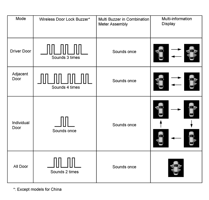
The entry unlock mode can be switched between the following 4 modes in accordance with the driver's intention:
-
Driver Door Mode
-
Adjacent Door Mode
-
Individual Door Mode
-
All Door Mode
-
-
The switching of the entry unlock mode is performed when the power source mode is off and the electrical key transmitter sub-assembly indicator light is not illuminated. Within a distance range of 1 m (3.3 ft) from the vehicle, press and hold both the lock button and any button of the electrical key transmitter sub-assembly (electrical key) other than the lock button for approximately 5 seconds.
-
During the switching of the entry unlock mode, the wireless door lock buzzer*, multi-information display or the multi buzzer in the combination meter assembly sounds to inform the driver of the state of the entry unlock mode.
-
*: Except models for China
-
-
-
Entry Unlock Function
-
When the electrical key transmitter sub-assembly is in the actuation area formed by the door electrical key oscillator, holding the outside door handle assembly of the driver seat and touching the built-in touch sensor unlocks the driver door only, and holding any of the passenger outside handle assemblies and touching the built-in touch sensor unlocks all the doors. (Driver door mode)
-
When the electrical key transmitter sub-assembly is in the actuation area formed by the door electrical key oscillator, holding any of the outside door handle assemblies and touching the built-in touch sensor unlocks all the doors. (All door mode)
-
When the electrical key transmitter sub-assembly is in the actuation area formed by the door electrical key oscillator, holding any of the outside door handle assemblies and touching the built-in touch sensor unlocks all of the doors on the same side. (Adjacent door mode)
-
When the electrical key transmitter sub-assembly is in the actuation area formed by the door electrical key oscillator, holding any of the outside door handle assemblies and touching the built-in touch sensor unlocks that door only. (Individual door mode)
-
After all doors have been unlocked, the wireless door lock buzzer sounds twice* as an answer back and the hazard lights flash twice at the same time.
-
*: Models with wireless door lock buzzer answer back function
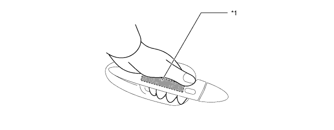
Text in Illustration *1 Touch Sensor - - -
-
-
Entry Lock Function
-
When the electrical key transmitter sub-assembly is in the actuation area formed by the door electrical key oscillator, pushing the lock switch of the outside door handle assembly locks all the doors.
-
After all doors have been locked, the wireless door lock buzzer sounds once* as an answer back and the hazard lights flash once at the same time.
-
*: Models with wireless door lock buzzer answer back function
Text in Illustration *1 Lock Switch - - -
-
-
Entry Luggage Compartment Door Opener Function
-
When the electrical key transmitter sub-assembly is in the actuation area formed by the electrical key antenna (outside luggage), pressing the luggage electrical key switch opens the luggage compartment door.
Tech Tips
When all the doors are unlocked, the luggage compartment door can be opened even without carrying the electrical key transmitter sub-assembly by pressing the luggage electrical key switch.
-
-
Memory Call Function
-
The electrical key transmitter sub-assembly linked memory call function uses the key ID of an electrical key transmitter sub-assembly to automatically restore the seat position (using the driving position memory system), shoulder belt anchor position, tilt and telescopic position and outside rear view mirror position, thus increasing driver convenience.
Condition Outline Memory Registration When all the following conditions are met, the key ID is recorded:
-
The engine switch is on (IG).
-
The driver door is closed.
-
The M1, M2 or M3 switch (front seat memory switch) is pushed and held.
-
The unlock button in the electrical key transmitter sub-assembly is pressed and held.
Memory Call Operation If the driver door is opened after the door is unlocked using the function of the entry function or the wireless door lock control function, the memory call function is operated. Memory Call Cancel When all the following conditions are met, the memory call function can be disabled:
-
The engine switch is on (IG).
-
The driver door is closed.
-
The SET switch (front seat memory switch) is pushed and held.
-
The unlock button in the electrical key transmitter sub-assembly is pressed and held.
-
-
Memory Registration
Step System Operation (a) The position control ECU assembly (driver seat) enters key ID registration mode (linking mode), if the M1, M2 or M3 switch (front seat memory switch) is pressed with the engine switch off and the driver door closed. (b) In this condition, when the unlock button on the electrical key transmitter sub-assembly is pressed, the key ID is transmitted from the certification ECU to the position control ECU assembly (driver seat). (c) The position control ECU assembly (driver seat) records the key ID and the driver seat position into the memory. (d) When the position control ECU assembly (driver seat) completes recording, it beeps the buzzer in the position control ECU assembly (driver seat) once as an answer back.
-
-
Warning Function
-
When any of the situations below occur, the entry and start system causes the certification ECU to sound the multi buzzer in the combination meter assembly and the wireless door lock buzzer* and to indicate a warning on the multi-information display in order to alert the driver.
-
*: Except models for China
Situation Condition A The engine is left running and the shift lever is in a position other than P when the driver gets out of the vehicle. B The electrical key transmitter sub-assembly is left in the vehicle. C The engine is left running and the shift lever is in P when the driver gets out of the vehicle. D A door is ajar. E The engine is left running when a passenger gets out of the vehicle holding the electrical key transmitter sub-assembly. F The electrical key transmitter sub-assembly is not within the actuation areas. G The electrical key transmitter sub-assembly is left in the cabin. H The electrical key transmitter sub-assembly is left in the luggage room. I The electrical key transmitter sub-assembly battery is low. J Steering lock does not release. K The steering lock mechanism is malfunctioning. L The main body ECU is malfunctioning. M An engine start method is displayed. -
-
There are 2 patterns for situation A.
Pattern 1: When the engine is left running and the shift lever is in a position other than P, the driver opens the door and attempts to get out of the vehicle. In this situation, the following control is performed:
Possible Effects without Warning Sudden vehicle start, vehicle theft, vehicle roll-away Warning Condition The warning is activated when all of the following conditions are met:
-
Power source mode is in a mode other than off.
-
Shift lever is in any position except P.
-
Vehicle speed is 0 km/h (0 mph).
-
Driver door is opened.
Warning Method Combination Meter Assembly Multi Buzzer Sounds continuously Master Warning Light - Multi-information Display The following warning message is displayed:
-
Shift to P range
Wireless Door Lock Buzzer - Engine Switch Indicator Light - Warning Stop Condition The warning is stopped when one of the following conditions is met:
-
Power source mode is turned off.
-
Shift lever is moved to P.
-
Vehicle speed is above 0 km/h (0 mph).
-
Driver door is closed.
Pattern 2: In addition to the conditions of pattern 1, the driver closes the door and attempts to leave the vehicle holding the electrical key transmitter sub-assembly. In these situations, the following control is performed:
Possible Effects without Warning Sudden vehicle start, Vehicle theft, Vehicle roll-away Warning Condition The warning is started when all the following conditions are satisfied:
-
Power source mode is anything other than off.
-
No electrical key transmitter sub-assembly is detected in the vehicle interior.
-
Shift lever is in any position other than P.
-
The state of the driver door is changed from open to closed.
-
Vehicle speed is 0 km/h (0 mph).
Warning Method Combination Meter Assembly Multi Buzzer Sounds continuously Master Warning Light Blinks Multi-information Display Shows the following warning messages alternately:
-
Shift to P range
-
Key is not detected
Advice Display Check key position Wireless Door Lock Buzzer* Sounds continuously Engine Switch Indicator Light - Warning Stop Condition The warning is stopped when one of the following conditions is met:
-
Power source mode is off.
-
An electrical key transmitter sub-assembly is detected in the vehicle interior (the multi-information display only shows "Shift to P range").
-
Vehicle speed is above 0 km/h (0 mph) (the multi-information display only shows "Key is not Detected").
-
*: Except models for China
-
-
There are 2 patterns for situation B.
Pattern 1: When the driver's door is open, the driver turned the power source mode on (ACC) and attempts to leave the vehicle.
Pattern 2: When the driver's door is open, the driver turned the power source mode from on (IG) to off and attempts to leave the vehicle. In these situations, the following control is performed:
Possible Effects without Warning Vehicle theft Warning Condition The warning is activated when one of the following conditions is met:
-
Power source mode is on (ACC) and the driver door is opened.
-
Power source mode is off, the steering is unlocked and the driver door is opened.
Warning Method Combination Meter Assembly Multi Buzzer Continues to sound at short and even intervals Master Warning Light - Multi-information Display - Advice Display - Wireless Door Lock Buzzer - Engine Switch Indicator Light - Warning Stop Condition The warning is stopped when one of the following conditions is met:
-
The power source mode is on (IG).
-
The driver door is closed.
-
The power source mode is off and steering is locked.
-
-
There are 2 patterns for situation C.
Pattern 1: When the engine is left running and the shift lever is in P, the driver closes the driver's door and attempts to leave the vehicle while holding the electrical key transmitter sub-assembly. In this situation, the following control is performed:
Possible Effects without Warning Vehicle theft, engine cannot be restarted, discharged battery Warning Condition The warning is activated when all of the following conditions are met:
-
Power source mode is in a mode other than off.
-
Shift lever is in P.
-
No electrical key transmitter sub-assembly is detected in the vehicle interior.
-
The state of the driver door is changed from open to closed.
Warning Method Combination Meter Assembly Multi Buzzer Sounds once Master Warning Light Blinks Multi-information Display The following warning message is displayed:
-
Key is not detected
Advice Display Check key position Wireless Door Lock Buzzer* Sounds 3 times Engine Switch Indicator Light - Warning Stop Condition The warning is stopped when one of the following conditions is met:
-
Power source mode is turned off.
-
An electrical key transmitter sub-assembly is detected in the vehicle interior.
-
*: Except models for China
Pattern 2: In addition to the conditions of pattern 1, the driver presses the lock switch on the outside door handle assembly. In these situations, the following control is performed:
Possible Effects without Warning Vehicle theft, discharged battery Warning Condition The warning is started when all the following conditions are satisfied:
-
Power source mode is anything other than off.
-
Shift lever is in P.
-
All doors are closed.
-
The key is outside the vehicle (within one of the actuation areas).
-
Lock switch is pushed.
Warning Method Combination Meter Assembly Multi Buzzer - Master Warning Light - Multi-information Display - Advice Display - Wireless Door Lock Buzzer* Sounds for 60 seconds Engine Switch Indicator Light - Warning Stop Condition The warning is stopped when one of the following conditions is met:
-
The power source mode is off and the electrical key transmitter sub-assembly is not within the actuation areas.
-
An electrical key transmitter sub-assembly is detected in the vehicle interior.
-
*: Except models for China
-
-
Situation D
The lock switch on the door outside handle is pressed to perform the entry lock function with a door open. In this situation, the following control is performed:
Possible Effects without Warning Vehicle theft Warning Condition The warning is started when all the following conditions are satisfied:
-
Power source mode is off.
-
Any door is open.
-
Lock switch is pushed.
Warning Method Combination Meter Assembly Multi Buzzer - Master Warning Light - Multi-information Display - Advice Display - Wireless Door Lock Buzzer* Sounds for 5 seconds Engine Switch Indicator Light - Warning Stop Condition The warning is stopped when one of the following conditions is met:
-
Power source mode is anything other than off.
-
Doors are unlocked through the wireless door lock control function.
-
An entry unlock operation is performed.
-
All doors are closed.
-
Approx. 5 seconds have elapsed from the time the warning started.
-
*: Except models for China
-
-
Situation E
When the engine is left running, a passenger leaves the vehicle holding the electrical key transmitter sub-assembly. In this situation, the following control is performed:
Possible Effects without Warning Engine cannot be restarted Warning Condition The warning is started when all the following conditions are satisfied:
-
Power source mode is turned to anything other than off.
-
The state of any door other than the driver door is changed from open to closed (the luggage compartment door is not included).
-
No electrical key transmitter sub-assembly is detected in the vehicle interior.
-
Vehicle speed is 0 km/h (0 mph).
Warning Method Combination Meter Assembly Multi Buzzer Sounds once Master Warning Light Blinks Multi-information Display The following warning message is displayed:
-
Key is not detected
Advice Display - Wireless Door Lock Buzzer* Sounds for 3 seconds Engine Switch Indicator Light - Warning Stop Condition The warning is stopped when one of the following conditions is met:
-
Power source mode is off.
-
Vehicle speed is above 0 km/h (0 mph).
-
An electrical key transmitter sub-assembly is detected in the vehicle interior.
-
*: Except models for China
-
-
Situation F
When the electrical key transmitter sub-assembly is not in the cabin or the electrical key transmitter sub-assembly battery is depleted, the driver attempts to start the engine or turn the power mode on (IG). In this situation, the following control is performed:
Possible Effects without Warning Vehicle theft Warning Condition The warning is started when all the following conditions are satisfied:
-
The engine switch is pressed.
-
No electrical key transmitter sub-assembly is detected in the vehicle interior.
Warning Method Combination Meter Assembly Multi Buzzer Sounds once Master Warning Light Blinks Multi-information Display The following warning message is displayed:
-
Key is not detected
Advice Display Check key position Wireless Door Lock Buzzer - Engine Switch Indicator Light - Warning Stop Condition If the electrical key transmitter sub-assembly is in the detection area, press the electrical key transmitter sub-assembly button and confirm that the indicator comes on. If the indicator does not come on, replace the electrical key transmitter subassembly battery with a new one. -
-
Situation G
The lock switch on the outside door handle is pressed to perform entry lock with the electrical key transmitter sub-assembly left in the cabin. In this situation, the following control is performed:
Possible Effects without Warning Vehicle theft Warning Condition The warning is started when all the following conditions are satisfied:
-
Power source mode is off.
-
All doors are closed.
-
An electrical key transmitter sub-assembly is detected in the vehicle interior.
-
Lock switch is pushed.
Warning Method Combination Meter Assembly Multi Buzzer - Master Warning Light - Multi-information Display - Advice Display - Wireless Door Lock Buzzer* Sounds for 2 seconds Engine Switch Indicator Light - Warning Stop Condition The electrical key transmitter sub-assembly is removed from the cabin and the lock switch on the outside door handle assembly is pressed again.
-
*: Except models for China
-
-
Situation H
The luggage compartment door is closed with an electrical key transmitter sub-assembly inside the luggage compartment. In this situation, the following control is performed:
Possible Effects without Warning Key confinement Warning Condition The warning is started when all the following conditions are satisfied:
-
Vehicle speed is 0 km/h (0 mph).
-
All doors are closed.
-
Luggage compartment door open function is available.
Warning Method Combination Meter Assembly Multi Buzzer - Master Warning Light - Multi-information Display - Advice Display - Wireless Door Lock Buzzer* Sounds for 2 seconds Engine Switch Indicator Light - Warning Stop Condition The luggage compartment door is opened using the entry luggage compartment door open function and the electrical key transmitter sub-assembly is removed from the luggage compartment.
-
*: Except models for China
-
-
Situation I
The electrical key transmitter sub-assembly battery is low. In this situation, the following control is performed:
Possible Effects without Warning Entry and start system does not function. Warning Condition The warning is activated when all of the following conditions are met:
-
After the power source mode has been on (IG) continuously for approx. 20 minutes or more, it is turned from on (IG) to off.
-
Electrical key transmitter sub-assembly battery is low.
-
An electrical key transmitter sub-assembly is detected in the vehicle interior.
-
Vehicle speed is 0 km/h (0 mph).
Or when all of the following conditions are satisfied:
-
Power source mode has been turned from off to on (IG) and the engine is running.
-
Electrical key transmitter sub-assembly battery is low.
-
An electrical key transmitter sub-assembly is detected in the vehicle interior.
-
Vehicle speed is 0 km/h (0 mph).
-
Warnings have occurred under situation I.
Warning Method Combination Meter Assembly Multi Buzzer Sounds once Master Warning Light Blinks Multi-information Display The following warning message is displayed:
-
Low Key Battery
Advice Display Have your vehicle checked by a dealer Wireless Door Lock Buzzer - Engine Switch Indicator Light - Warning Stop Condition The electrical key transmitter sub-assembly battery is replaced with a new one. -
-
Situation J
The steering lock cannot be released. In this situations, the following control is performed:
Possible Effects without Warning Steering usability function Warning Condition The steering lock does not release when performing the release operation, preventing the engine from starting. Warning Method Combination Meter Assembly Multi Buzzer - Master Warning Light Blinks Multi-information Display The following warning message is displayed:
-
Steering Lock is still active
Advice Display Push the engine switch while turning the steering wheel in either direction Wireless Door Lock Buzzer - Engine Switch Indicator Light The green indicator blinks at 1-second intervals (goes off automatically in 15 seconds). Warning Stop Condition The engine switch is pressed while the steering wheel is turned left and right, and the steering lock successfully disengages. -
-
Situation K
A malfunction of the steering lock ECU is detected. In this situation, the following control is performed:
Possible Effects without Warning Malfunction detection Warning Condition A malfunction of the steering lock ECU is detected. Warning Method Combination Meter Assembly Multi Buzzer - Master Warning Light Blinks Multi-information Display The following warning message is displayed:
-
Check Steering Lock System
Advice Display Have your vehicle checked by a dealer Wireless Door Lock Buzzer - Engine Switch Indicator Light The amber indicator blinks at 2-second intervals. Warning Stop Condition The steering lock ECU returns to normal. -
-
Situation L
A malfunction of the main body ECU is detected. In this situation, the following control is performed:
Possible Effects without Warning Malfunction detection Warning Condition A malfunction in the main body ECU is detected. Warning Method Combination Meter Assembly Multi Buzzer - Master Warning Light - Multi-information Display - Wireless Door Lock Buzzer - Engine Switch Indicator Light The amber indicator blinks at 2-second intervals. Warning Stop Condition The main body ECU returns to normal. -
Situation M
A warning message appears on the meter when the driver does not follow the proper procedure to start the vehicle. In this situation, the following control is performed:
Possible Effects without Warning Usability function Warning Condition The warning is started when all the following conditions are satisfied:
-
Power source mode is turned to anything other than on (IG).
-
Any door is open.
-
The power source mode is turned from off to on (ACC) more than once with the engine off and the brake pedal not depressed.
Warning Method Combination Meter Assembly Multi Buzzer - Master Warning Light - Multi-information Display The following warning message is displayed:
-
To start, depress the brake pedal, and push the engine switch
Advice Display 
Wireless Door Lock Buzzer - Engine Switch Indicator Light - Warning Stop Condition The warning is stopped when one of the following conditions is met:
-
10 seconds have elapsed since a warning message was displayed.
-
The engine switch is pushed with the brake pedal depressed or with the power source mode off.
-
-
-
Battery Saving Function
-
Vehicle Battery Saving
-
In the entry and start system, signals are emitted outside the vehicle at a prescribed interval (250 msec.) when the doors are locked. Therefore, the vehicle battery could be drained if the vehicle remains parked for a long time. For this reason, the controls listed below are effected:
Condition Control No response from key for 10 to 14 days Signal transmission interval is extended from 250 msec. to 750 msec. No response from key for 15 to 30 days Signal transmission interval is extended from 750 msec. to 2250 msec. No response from key for more than 31 days The entry and start system is automatically deactivated. -
Revert Condition
-
A wireless door lock control signal is input and the ID matches.
-
A user carries the electrical key transmitter sub-assembly and pushes a lock switch an the outside door handle assembly.
-
A door is locked or unlocked using the mechanical key.
-
-
Electrical Key Transmitter Sub-assembly Battery and Vehicle Battery Saving Function
-
In the entry and start system, if the electrical key transmitter sub-assembly is constantly located within the vehicle exterior actuation area of the doors, the system maintains periodic communication with the electrical key transmitter sub-assembly. Therefore, if the vehicle remains parked in that state for a long time, the electrical key transmitter subassembly battery and the vehicle battery could be drained. For this reason, if this state continues longer than 10 minutes, the entry and start system automatically becomes deactivated.
-
Revert Condition
-
A wireless door lock control signal is input and the ID matches.
-
A user who has the electrical key transmitter sub-assembly in their possession pushes a lock switch on an outside door handle assembly.
-
A door is locked or unlocked using the mechanical key.
-
-
-
Key Cancel Function
-
Key cancel is operated when certain operations are performed with the vehicle in the following condition:
-
Power source mode is off.
-
Driver door is closed.
-
Driver door is unlocked.
-
-
The operation procedure is as follows:
Key Cancel Procedure
-
Unlock once with the unlock button of the electrical key transmitter sub-assembly.
-
Open the driver door within 5 seconds.
-
Unlock twice with the unlock button of the electrical key transmitter sub-assembly within 5 seconds.
-
Repeat open → close twice for the driver door within 30 seconds, and open again. (Driver Door: Open → Close → Open → Close → Open)
-
Unlock twice with the unlock button of the electrical key transmitter sub-assembly within 30 seconds.
-
Repeat open → close once for the driver door within 30 seconds, and open again. (Driver Door: Open → Close → Open)
-
Close the driver door within 5 seconds.
When key cancel is activated, the wireless door lock buzzer sounds twice.* To return to the original condition, perform the procedures again. When key cancel is returned in its original condition, the wireless door lock buzzer sounds once.
-
*: Except models for China
-
-
-
Key Code Registration Function
-
The table below shows the 4 special ID code registration function modes through which up to 7 different codes can be registered. The codes are electronically registered (written and stored) in the EEPROM. For details, refer to the Service Bulletin.
Mode Function Rewrite Clears all previously registered codes and registers only the newly received codes. This mode is used whenever an electrical key transmitter sub-assembly or an integration relay is replaced. Add Adds a newly received code while preserving previously registered codes. This mode is used when adding a new electrical key transmitter sub-assembly. If the number of codes exceeds 7, the oldest registered code is erased first. Confirm Confirms how many codes are currently registered. When adding a new code, this mode is used to check how many codes already exist. Prohibit Clears all registered codes and prohibits the wireless door lock function. This mode is used when an electrical key transmitter sub-assembly is lost.
-
-
-
CONSTRUCTION
-
Electrical Key Transmitter Sub-assembly (Electrical Key)
-
The electrical key transmitter sub-assembly (electrical key) consists of a mechanical key, a transmitter for the wireless door lock control and a transceiver for the entry and start system.
-
The transceiver for the entry and start system receives the signals from the electrical key antennas and returns the ID code to the door control receiver.
-
The electrical key transmitter sub-assembly for the wireless door lock control has a lock button, unlock button, luggage compartment door opener button and panic button*.
-
*: Models with panic alarm function
-
-
This mechanical key works for the driver door, but cannot be used to start the engine.
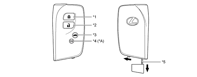
Text in Illustration *A Models with Panic Alarm Function - - *1 Lock Button *2 Unlock Button *3 Luggage Compartment Door Opener Button *4 Panic Button *5 Mechanical Key - -
-
-
Electrical Key Transmitter Sub-assembly (Card Key)
-
The electrical key transmitter sub-assembly (card key) consists of a mechanical key and a transceiver for the entry and start system.
-
The transceiver for the entry and start system receives the signals from the electrical key antennas and returns the ID code to the door control receiver.
-
This mechanical key works for the driver door, but cannot be used to start the engine.
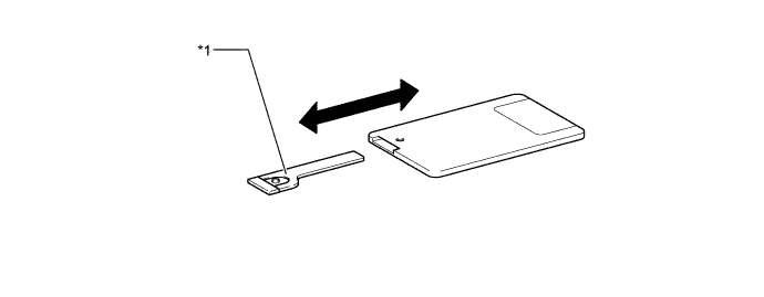
Text in Illustration *1 Mechanical Key - -
-
-
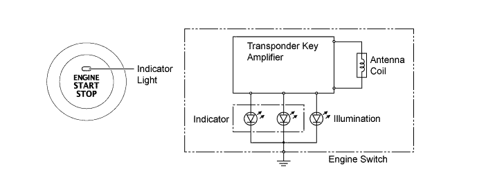
Engine Switch
-
The engine switch consists of a momentary type switch, indicator light (amber and green color LEDs), illumination, antenna coil and transponder key amplifier.
-
The driver can determine the present power source and check whether the engine can start or not in accordance with the illumination state of the indicator light.
-
If the main body ECU detects an abnormality with the entry and start system, the ECU makes the amber indicator light flash. If the engine is stopped in this state, it might not be possible to restart it.
Power Source Mode/Condition Indicator Light Condition Brake pedal not depressed Brake pedal depressed with shift lever in P or N Off Off On (Green) On (ACC), On (IG) On (Amber) On (Green) Engine Running Off Off Steering Lock not Unlocked Flashes (Green) for 15 seconds Flashes (Green) for 15 seconds Entry and Start System Malfunction Flashes (Amber) for 15 seconds Flashes (Amber) for 15 seconds
-
-
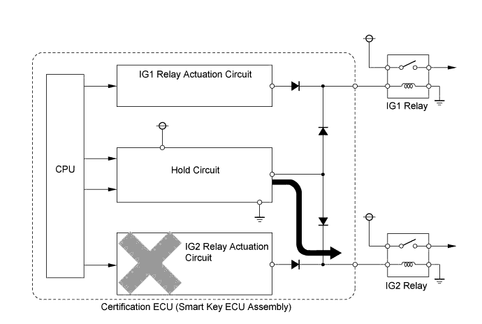
Main Body ECU
-
The main body ECU consists of the IG1 and IG2 relay actuation circuits, CPU and hold circuit.
-
The hold circuit is installed to prevent the power supply to the relays from being cut off when an abnormality occurs in the IG1 and/or IG2 relay actuation circuits while driving.
Tech Tips
The main body ECU constantly stores the present power source mode in its memory.
Therefore, if the power to the main body ECU is interrupted due to the removal of the battery, the main body ECU restores the power source mode after the battery is reconnected.
For this reason, if the battery is removed when the engine switch is in any position other than off, the power is restored to the vehicle at the same time the power is restored to the main body ECU (by reconnecting the battery).
Therefore, before removing or disconnecting the battery, make sure to turn the engine switch off.
-
-
-
DIAGNOSIS
-
The main body ECU can detect malfunctions in the entry and start system when the engine switch is on (IG).
-
When the ECUs detect a malfunction, the amber indicator light of the engine switch flashes to warn the driver. At the same time, the ECUs store 5-digit Diagnostic Trouble Code (DTC) in their memories.
-
The indicator light warning continues for 15 seconds even after the engine switch is turned off.
-
The 5-digit DTCs can be read after connecting the Global TechStream (GTS) to the DLC3.
-
The entry and start system may not operate successfully if a malfunction occurs.
-