EXHAUST SYSTEM DETAILS
-
CONSTRUCTION
-
Exhaust Manifold Sub-assembly
-
Stainless steel exhaust manifolds with integrated ceramic type Three-Way Catalysts (TWCs) are used for warming up the TWCs, reducing weight and resisting rust.
-
On the 2WD models, the exhaust manifold for each bank uses a semi-dual structure (a 4-2-1 grouping). This structure combines the 4 exhaust ports of one bank into 2 groups, then the 2 groups into 1 group, before the TWC. This reduces exhaust gas interference and improves power output.
-
The heat insulator is made of corrugated aluminum. This ensures rigidity, and at the same time, increases the surface area to improve heat dissipation. Furthermore, a floating construction is used at the tightened area to reduce the transfer of heat and vibration to the heat insulator and to improve reliability.
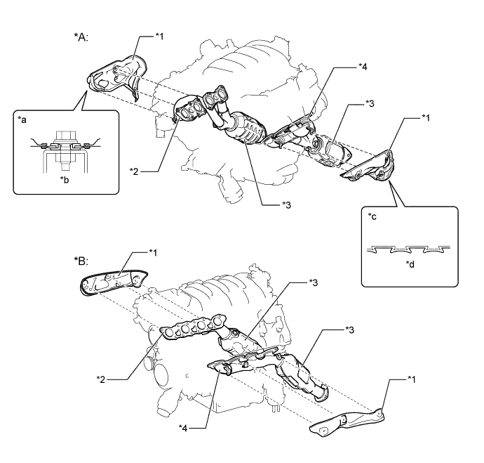
Text in Illustration *A 2WD *B AWD *1 Heat Insulator *2 Exhaust Manifold Sub-assembly RH *3 TWC *4 Exhaust Manifold Sub-assembly LH *a Heat Insulator Tightened Area Cross Section *b Floating Construction *c Heat Insulator Cross Section *d Corrugated
-
-
Exhaust Pipe
-
The exhaust pipes are made of stainless steel for improved rust resistance.
-
Ceramic type TWCs in the front exhaust pipe assemblies are used.
-
The exhaust system uses full dual straight construction in which the left bank and the right bank portions of the exhaust manifold to the tail pipe end are independent. This construction prevents pressure loss and achieves high power output by optimizing the shape and the length of the exhaust pipes, and the diameter of the pipes. Furthermore, with a portion of the exhaust gas, it allows interference in order to eliminate noise in a specific frequency range and to improve quietness.
-
On the 2WD models except F SPORT, the sub-muffler uses a construction that functions as both a sound absorption material and a resonance chamber. This simultaneously reduces exhaust noises in both the high and low frequency ranges. Stainless wool and roving wool are used as sound absorption materials in order to eliminate exhaust noise in the high-frequency range. The resonance chamber eliminates exhaust noise in the low-frequency range.
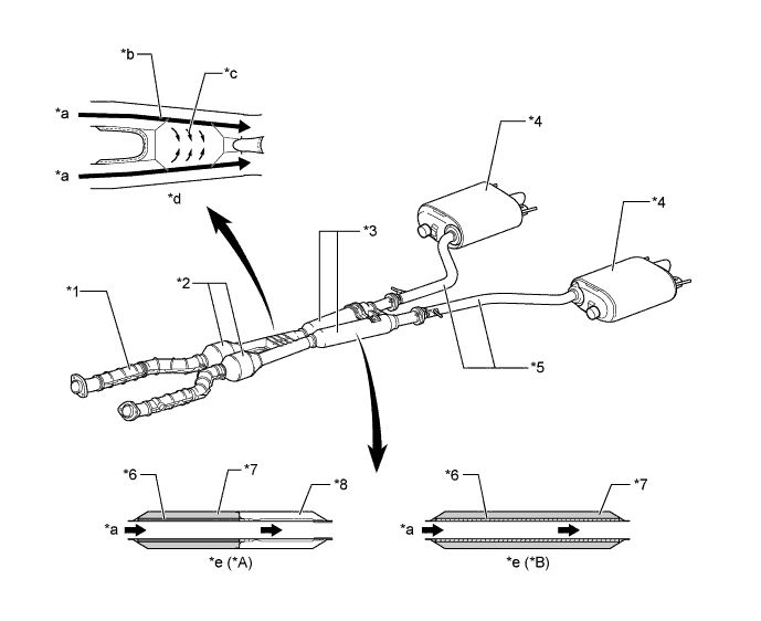
Text in Illustration *A 2WD Models Except F SPORT *B AWD Models and F SPORT *1 Front Exhaust Pipe Assembly *2 TWC *3 Sub-muffler *4 Main Muffler *5 Tail Exhaust Pipe Assembly *6 Stainless Wool *7 Roving Wool *8 Resonance Chamber *a Exhaust Gas *b Main Flow *c Sub Flow *d Front Exhaust Pipe Top View Image Drawing *e Sub-muffler Cross Section - -
-
-
Main Muffler
-
Dual main mufflers are used to ensure engine performance and to reduce exhaust noise.
-
A long tail mechanism is used in the main mufflers to reduce exhaust noise while the engine is running in the low speed range.
-
The end plate and the shell are laser-welded to optimize the joint shape and to improve aerodynamic characteristics.
-
On AWD models and F SPORT models, a valveless muffler is used to improve sound quality and improved performance is achieved by reducing exhaust pressure.
-
On the 2WD models except F SPORT, a 2-way exhaust control system is provided in the main muffler.
-
This system reduces the back pressure by opening and closing a variable valve that is enclosed in the main muffler, thus varying the exhaust gas pressure.
-
The valve opens steplessly in accordance with the operating condition of the engine, thus enabling a quieter operation at lower engine speeds and reducing back pressure at higher engine speeds.
-
The control valve is enclosed in the main muffler. When the exhaust gas pressure overcomes the spring pressure, the control valve opens steplessly in accordance with the exhaust gas pressure.
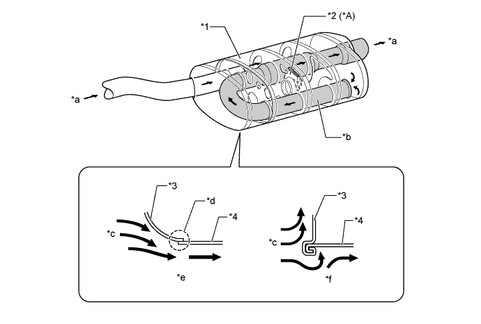
Text in Illustration *A 2WD Models Except F SPORT - - *1 Main Muffler *2 Exhaust Control Valve *3 End Plate *4 Shell *a Exhaust Gas *b Long Tail Mechanism *c Driving Airflow *d Laser-welding Portion *e Laser-welding *f Conventional -
-
-
-
OPERATION
-
2-way Exhaust Control System (2WD Models Except F SPORT)
-
When Control Valve is Closed (Low Engine Speed)
-
Since the pressure in the main muffler is low, the control valve is closed. Hence exhaust gas does not pass the bypass passage, and exhaust noise is decreased in the main muffler.
-
-
When Control Valve is Open (Middle to High Engine Speed)
-
The valve opens as the engine speed and the back pressure in the muffler increase. This allows a large volume of exhaust gas to pass the bypass passage, thereby substantially decreasing the back pressure.
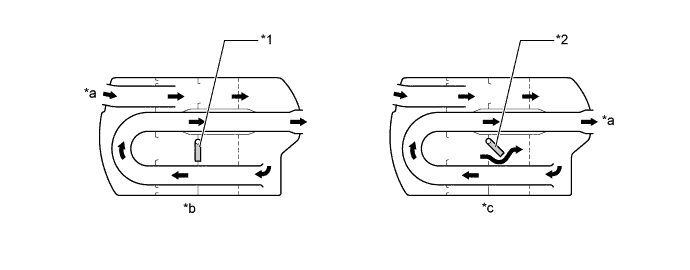
Text in Illustration *1 Control Valve (Closed) *2 Control Valve (Open) *a Exhaust Gas *b Low Engine Speed *c Middle to High Engine Speed - - -
-
-