FUEL SYSTEM DETAILS
-
CONSTRUCTION
-
Fuel Pump (for Low Pressure)
-
A fuel pump (for low pressure) that has an integrated fuel filter and a sender gauge is used.
-
The low-pressure fuel pump is located in the fuel tank. This pump pressurizes fuel to 400 kPa in order to send the fuel from the fuel tank to the high and low pressure fuel systems.
-
A low-current fuel pump is used to minimize power consumption and to improve fuel economy.
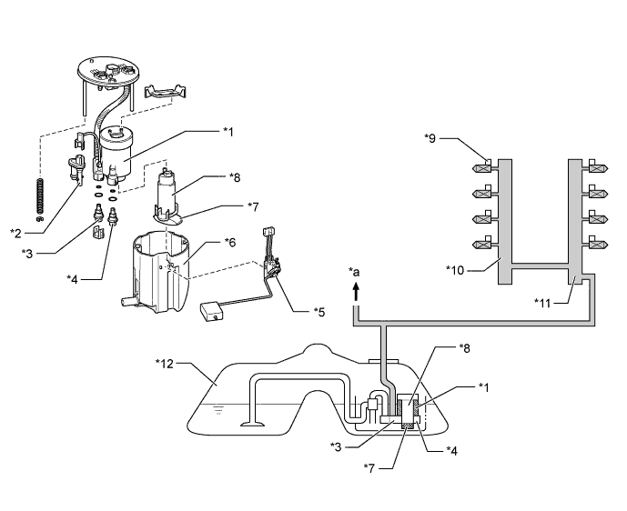
Text in Illustration *1 Fuel Filter *2 Jet Pump *3 Fuel Main Valve *4 Fuel Pressure Regulator Assembly *5 Sender Gauge *6 Reservoir Cup *7 Suction Filter *8 Fuel Pump *9 Fuel Injector Assembly *10 Fuel Delivery Pipe Sub-assembly LH *11 Fuel Delivery Pipe Sub-assembly RH *12 Fuel Tank Assembly *a To High-pressure Fuel System - -
-
-
Fuel Pump (for High Pressure)
-
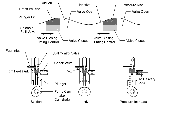
The fuel pump consists of a plunger, a spill control valve and a check valve. A pulsation damper is also installed at the fuel inlet. The pulsation damper pressurizes the fuel that is sent by the low-pressure fuel pump to a pressure ranging from 4 MPa to 13 MPa and sends it to the high-pressure delivery pipe.
-
A pump cam that is fitted on the intake camshaft moves the plunger vertically. This pump cam has an oval shape, allowing the plunger to make 2 strokes for every revolution of the camshaft.
-
A spill control valve is used to control the pump discharge pressure. The spill control valve is located in the inlet passage of the pump. The valve is electrically opened and closed by the injector driver (EDU) based on instructions from the ECM.
-
A check valve is present in the outlet of the pump. As the pressure in the outlet of the pump rises, and becomes high enough to push the check valve off its seat, fuel begins to flow to the delivery pipe (minimum pressure to open the check valve is 60 kPa).
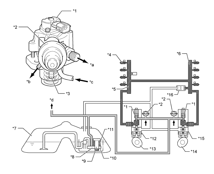
Text in Illustration *1 Spill Control Valve *2 Pulsation Damper *3 Plunger *4 Fuel Injector Assembly *5 Fuel Delivery Pipe Sub-assembly LH *6 Fuel Delivery Pipe Sub-assembly RH *7 Fuel Tank Assembly *8 Fuel Main Valve *9 Fuel Pump (for Low Pressure) *10 Fuel Pressure Regulator Assembly *11 Fuel Filter *12 Fuel Pump LH (for High Pressure) *13 Pump Cam LH (Intake Camshaft) *14 Pump Cam RH (Intake Camshaft) *15 Fuel Pump RH (for High Pressure) *16 Relief Valve *a To Fuel Delivery Pipe Sub-assembly (for Direct Injection) *b To Fuel Tank Assembly *c From Fuel Pump (for Low Pressure) *d To Low-pressure Fuel System 
Fuel Pump RH (for High Pressure) 
Relief Valve
-
-
Fuel Delivery Pipe Sub-assembly (for Port Injection)
-
Stamped steel fuel delivery pipe sub-assemblies are used (for port injection) to deliver low-pressure fuel to the fuel injector assemblies (for port injection).
-
An inner pipe inside the delivery pipe is used to absorb fuel pulsations. This eliminates the use of the pulsation damper provided on the conventional models, making the fuel system more compact and lightweight. When fuel pulsates, the shape of the inner pipe changes with the pulsation, thus changing the internal capacity of the delivery pipe. This change in capacity absorbs the fuel pulsations.
-
The wiring harnesses that connect to the injectors (for port injection) are combined into a single strand at each bank. Furthermore, the wiring harnesses connect to the ECM at a single connector for improved serviceability.
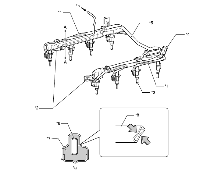
Text in Illustration *1 Wiring Harness *2 Fuel Delivery Pipe Sub-assembly (for Port Injection) *3 Fuel Injector Assembly (for Port Injection) *4 Connector *5 Coupling Fuel Pipe *6 Inner Pipe *7 Fuel *8 Inner Pipe (for Absorbing Pulsation) *a A - A Cross Section *b Fuel (from Fuel Tank)
-
-
Fuel Delivery Pipe Sub-assembly (for Direct Injection)
-
Aluminum alloy steel fuel delivery pipe sub-assemblies (for direct injection) are used for delivering high-pressure fuel to the fuel injector assemblies (for direct injection).
-
A fuel pressure sensor and a relief valve are installed on the fuel delivery pipe.
-
An injector clamp is provided for each area of the fuel delivery pipe where a high-pressure fuel injector is installed. This clamp applies a constant spring force to the injector to prevent the injector from moving when the combustion pressure is applied to the injector while the engine is being started, during which the fuel pressure is low. As a result, it increases the sealing performance of the injector, while reducing vibration and noise.
-
An O-ring and backup rings are used in the areas in which the high-pressure fuel injectors and high-pressure fuel delivery pipes are joined. This reduces the transmission of the operating sounds of the high-pressure fuel injectors, enhances quiet operation and ensures the sealing performance of the joined areas.
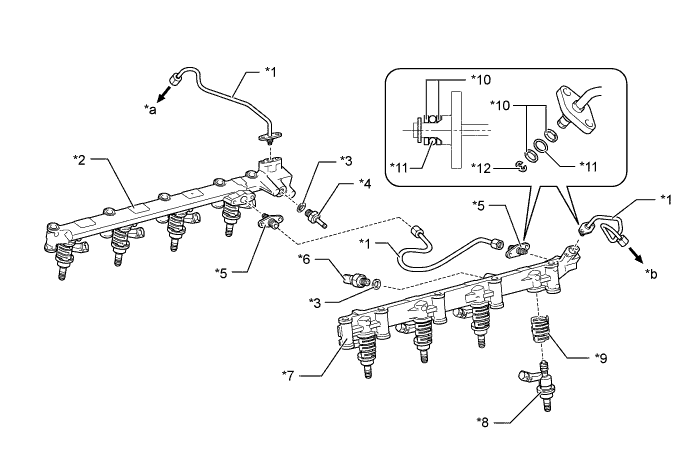
Text in Illustration *1 Fuel Pipe *2 Fuel Delivery Pipe Sub-assembly RH (for Direct Injection) *3 Gasket *4 Relief Valve *5 Fuel Union *6 Fuel Pressure Sensor *7 Fuel Delivery Pipe Sub-assembly LH (for Direct Injection) *8 Fuel Injector Assembly (for Direct Injection) *9 Injector Clamps *10 Backup Ring *11 O-ring *12 E-ring *a To Fuel Pump RH (for High Pressure) *b To Fuel Pump LH (for High Pressure) Tech Tips
The backup rings are provided to securely support the rubber O-ring which is exposed to high fuel pressure. During assembly, make sure to install them in the correct position and orientation.
-
-
Relief Valve
-
A relief valve is provided in the fuel delivery pipe. When the fuel pressure in the fuel delivery pipe rises above 15.3 MPa, the relief valve limits the pressure by returning fuel to the fuel tank.
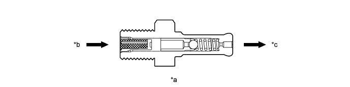
Text in Illustration *a Cross Section *b From Fuel Delivery Pipe Sub-assembly (for Direct Injection) *c To Fuel Tank - -
-
-
Fuel Injector Assembly (for Port Injection)
-
Compact and lightweight 12-hole type injectors are used as fuel injectors for port injection.
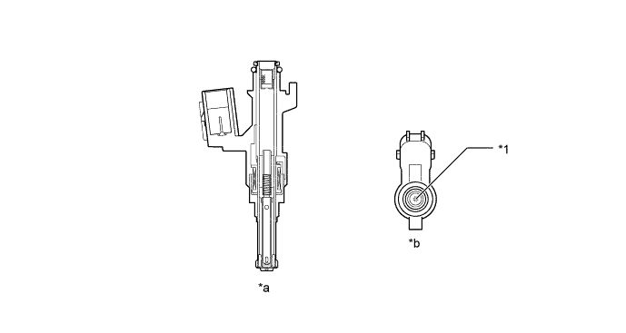
Text in Illustration *1 Injection Nozzle - - *a Cross Section *b View from Bottom Side
-
-
Fuel Injector Assembly (for Direct Injection)
-
Double slit-nozzle type injectors which have 2 slit-shaped injection orifices are used as fuel injectors for direct injection.
-
Each injector, based on signals from the ECM, meters the flow of high pressure fuel. The fuel is injected directly to the combustion chamber as a fine-atomized mist in a fan-shaped pattern via a slit type nozzle.
-
An insulator is used in the area where the injector contacts the cylinder head, and Teflon shaft seals are used to seal the injector against the combustion pressure in the cylinder. This is performed in order to reduce vibration and noise and to enhance sealing performance.
-
Each nozzle tip is coated to reduce the adhesion of deposits.
-
Each injector is actuated by the injector drivers (EDUs). Based on signals received from the ECM, the injector drivers (EDUs) apply an initial high voltage of 50 V and high current of 9.7 A to the injectors in order to open the needle valves quickly. Once the injectors are open, the injector drivers (EDUs) apply a constant voltage of 12 V and current of 2 A, in order to maintain the open state efficiently. This control allows the injectors to inject high-pressure fuel in a short amount of time.
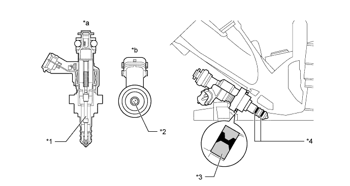
Text in Illustration *1 Needle Valve *2 Injection Nozzle *3 Insulator *4 Teflon Shaft Seals *a Cross Section *b View from Bottom Side
-
-
Fuel Tank Assembly
-
A fuel tank made of steel is used.
-
Drain marks have been provided at the lowest position of the fuel tank. When dismantling (scraping) the vehicle, drain fuel by drilling holes at the drain mark.
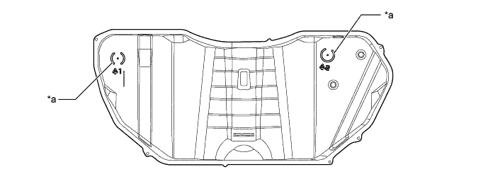
Text in Illustration *a Drain Mark - - -
The fuel tank uses a saddle shape to allow the propeller shaft to pass under the center portion of the tank. Also, a jet pump is used to transfer the fuel from the side of the tank without the fuel pump to the side with the fuel pump.
-
A jet pump is used in the fuel tank. The propeller shaft is located below the raised center of the bottom of the fuel tank. The fuel tank is shaped as indicated below.
-
A fuel tank with such a shape tends to cause fuel to be present in both chamber A and chamber B when the fuel level is low. This stops the fuel in chamber B from being pumped out. To prevent this from occurring, a jet pump is provided to transfer the fuel from chamber B to chamber A.
-
This is accomplished by utilizing the flow of the fuel through the jet pump, so that the pressure difference created by the fuel as it passes through the venturi is used to suck the fuel out of chamber B and send it to chamber A.
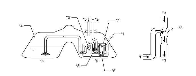
Text in Illustration *1 Fuel Filter *2 Fuel Pump *3 Jet Pump *4 Fuel Tank Assembly *5 Fuel Main Valve *6 Suction Filter *a To Engine *b From Engine *c Chamber B *d Chamber A *e From Fuel Main Valve *f From Chamber B *g To Chamber A (Reservoir Cup) - -
-
-
-
OPERATION
-
Fuel Pump (for High Pressure)
-
During the intake portion of the pump cycle, the spill control valve is opened and the pump plunger (piston) is moved downward by a spring force. This allows fuel to be drawn in to the cylinder of the pump. If the spill control valve is not closed, when the cam forces the plunger to move upward, the fuel in the pump cylinder (this fuel is not pressurized) will be pushed back to the pump inlet (fuel tank side).
-
In order to close the spill control valve as the piston is moving upward, the ECM sends a signal to the valve via the injector driver (EDU). When the spill control valve is closed and the plunger is moving upward, the pressure in the pump cylinder rises. As this pressure rises above 60 kPa (or the pressure of the delivery pipe, whichever is higher), the fuel begins to flow to the delivery pipe. The ECM calculates the target fuel pressure based on driving conditions. The ECM controls the pressure by operating the spill control valve via the injector driver (EDU). The timing and duration of the spill control valve closing is varied to cause the pump pressure to meet the target pressure.
-
-