SFI SYSTEM DETAILS
-
FUNCTION OF MAIN COMPONENTS
-
The main components of the engine control system are as follows:
Component Outline Quantity Function ECM 32-bit CPU 1 The ECM optimally controls the SFI, ESA and ISC to suit the operating conditions of the engine in accordance with the signals provided by the sensors. Intake Mass Air Flow Meter Sub-assembly Hot-wire Type 2 This sensor has a built-in hot-wire to directly detect the intake air mass. Intake Air Temperature Sensor Thermistor Type 2 This sensor detects the intake air temperature by means of an internal thermistor. Crankshaft Position Sensor MRE Type
(Rotor Teeth / 36-2)
1 This sensor detects the engine speed and the crankshaft position. Camshaft Position Sensor MRE Type
(Rotor Teeth / 3)
1 This sensor detects the camshaft position and performs the cylinder identification. Intake VVT Sensor MRE Type
(Rotor Teeth / 3)
1 each bank This sensor detects the actual valve timing. Exhaust VVT Sensor MRE Type
(Rotor Teeth / 3)
1 each bank This sensor detects the actual valve timing. Accelerator Pedal Sensor Assembly Hall IC Type
(No-contact Type)
1 This sensor detects the amount of pedal effort applied to the accelerator pedal. Throttle Position Sensor Hall IC Type
(No-contact Type)
1 This sensor detects the throttle valve opening angle. Knock Control Sensor Built-in Piezoelectric Element
(Flat Type)
2 each bank This sensor detects an occurrence of the engine knocking indirectly from the vibration of the cylinder block caused by the occurrence of engine knocking. Oxygen Sensor Cup Type with Heater 1 each bank This sensor detects the oxygen concentration in the exhaust emissions by measuring the electromotive force which is generated in the sensor itself. Air Fuel Ratio Sensor Planar Type with Heater 1 each bank As with the oxygen sensor, this sensor detects the oxygen concentration in the exhaust emissions. However, the sensor detects the oxygen concentration in the exhaust emissions linearly. Engine Coolant Temperature Sensor Thermistor Type 1 This sensor detects the engine coolant temperature by means of an internal thermistor. Fuel Injector Assembly
(for Port Injection)
12-hole Type 8 This injector contains an electro-magnetically operated nozzle to inject fuel into the intake port. Fuel Injector Assembly
(for Direct Injection)
High Pressure Double Slit Nozzle Type 8 This injector contains a high-pressure electro-magnetically operated nozzle to inject fuel directly into the cylinder. Injector Driver (EDU) Built-in DC/DC Converter 2 The injector driver converts the signals from the ECM into high-voltage, high-amperage current in order to drive the direct injection injectors. Camshaft Control Motor EDU-integrated
(Brushless Type DC Motor)
1 each bank The rotational movement of the camshaft control motor changes the intake valve timing by operating the camshaft control actuator in accordance with the signals received from the ECM. Camshaft Timing Oil Control Valve Electro-magnetic Coil Type 1 each bank The camshaft timing oil control valve changes the exhaust valve timing by switching the oil passage that acts on the VVT-i controller in accordance with the signals received from the ECM.
-
-
SYSTEM CONTROL
-
The engine control system has the following features. The ECM controls these systems:
System Outline Direct Injection 4-stroke Gasoline Engine Superior Version Sequential Multiport Fuel Injection (D-4S SFI)
-
The D-4S SFI system directly detects the intake air mass with a hot-wire type mass air flow meters.
-
The D-4S system is a fuel injection system which combines direct injection injectors and port injection injectors.
-
Based on signals from each sensor, the ECM controls the injection volume and timing of each type of injector (direct and port injection types) in accordance with the engine speed and the engine load in order to optimize combustion conditions.
Electronic Spark Advance (ESA)
-
Ignition timing is determined by the ECM based on signals from various sensors. The ECM corrects ignition timing in response to engine knocking.
-
This system selects the optimal ignition timing in accordance with the signals received from the sensors and sends the ignition signal (IGT) to the igniters.
Electronic Throttle Control System-intelligent (ETCS-i) Optimally controls the throttle valve opening in accordance with the amount of accelerator pedal effort and the conditions of the engine and the vehicle. Dual Variable Valve Timing-intelligent (Dual VVT-i)
-
Controls the intake and exhaust camshafts to an optimal valve timing in accordance with the engine conditions.
-
The intake side is VVT-iE and uses an electric motor to control the valve timing. The exhaust side is VVT-i and uses engine oil pressure to control the valve timing.
Acoustic Control Induction System (ACIS) The intake air passages are switched in accordance with the engine speed and throttle valve opening angle to provided high performance in all speed ranges. Fuel Pump Control For High Pressure Side Regulates the fuel pressure within a range of 4 MPa to 13 MPa in accordance with the driving conditions. For Low Pressure Side
-
Fuel pump operation is controlled by signals from the ECM.
-
The fuel pump is stopped when the SRS airbag is deployed.
Air Fuel Ratio Sensor and Oxygen Sensor Heater Control Maintains the temperature of the air fuel ratio sensors and heated oxygen sensors at an appropriate level to increase accuracy of detection of the oxygen concentration in the exhaust gas. Air Conditioning Cut-off Control By turning the air conditioning compressor on or off in accordance with the engine condition, drivebility is maintained. Cooling Fan Control The cooling fan ECU steplessly controls the speed of the fans in accordance with the engine coolant temperature, vehicle speed, engine speed and air conditioning operating conditions. As a result, the cooling performance is improved. Starter Control
(Cranking Hold Function)
Once the engine switch is pushed while the brake pedal is depressed, this control continues to operate the starter until the engine started. Charging Control Function
-
The ECM lowers the generated voltage when the vehicle is idling or is being driven at a constant speed, and raises the generated voltage when the vehicle is decelerating. This reduces the load on the engine, contributing to the fuel economy of the engine.
-
This function is one of the functions of the electric power control system.
Brake Override System Restricts the driving torque when the brake pedal is applied while the accelerator pedal is depressed. (For the Activation Conditions and Inspection Method, refer to the Repair Manual.) Immobiliser System Prohibits fuel delivery and ignition if an attempt is made to start the engine with an invalid key. Diagnosis When the ECM detects a malfunction, it records the malfunction and information that relates to the fault. Fail-safe When the ECM detects a malfunction, it stops or controls the engine according to the data already stored in memory. -
-
-
FUNCTION
-
Direct Injection 4-stroke Gasoline Engine Superior Version Sequential Multiport Fuel Injection (D-4S SFI) System
-
A D-4S SFI system directly detects the intake air mass with a hot-wire type intake mass air flow meter sub-assembly.
-
The D-4S system is a fuel injection system which combines direct injection injectors and port injection injectors.
-
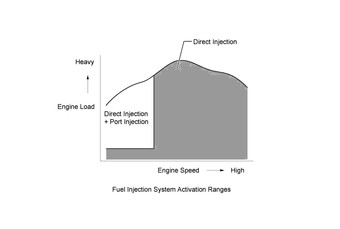
Based on signals from each sensor, the ECM controls the injection volume and timing of each type of injector (direct and port injection types) in accordance with engine load and engine speed in order to optimize combustion conditions.
-
To promote warm-up of the catalyst after a cold engine start, this system uses a stratified air-fuel mixture that results in an area near the spark plug that is richer than the rest of the air-fuel mixture. This allows a retarded ignition timing to be used, so the exhaust gas temperature can be increased. This results in more rapid heating of the catalytic converters, reducing exhaust emissions.
-
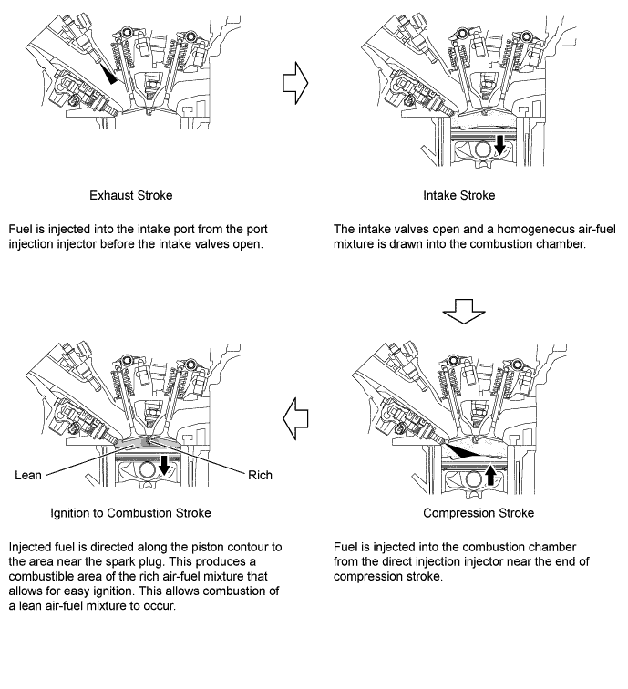
Stratification Combustion: Immediately after a cold engine start, fuel is injected into the intake port from the port injection injector during the exhaust stroke. Fuel is also injected from the direct injection injector near the end of the compression stroke. This results in an air-fuel mixture that is stratified, and the area near the spark plug is richer than the rest of the air-fuel mixture. This allows a retarded ignition timing to be used, raising the exhaust gas temperature. The increased exhaust gas temperatures promote rapid warm-up of the catalyst, and significantly improve exhaust emission performance.
-
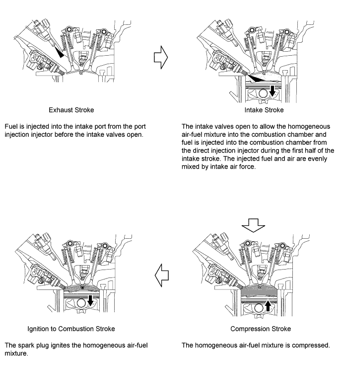
Homogeneous Combustion: To optimize combustion conditions, the ECM controls injection volume and timing of the port injection injectors which inject fuel into the intake ports during the expansion, exhaust and intake strokes. The ECM also controls the injection volume and timing of the direct injection injectors which inject fuel during the first half of the intake stroke. The homogeneous air-fuel mixture is created by either combined or individual use of the 2 different types of injectors. This allows utilization of the heat of evaporation of the injected fuel to cool the compressed air, and also allows an increase of charging efficiency and power output.
-
-
Dual VVT-i System
-
The Dual VVT-i system is designed to control the intake and exhaust camshafts within a range of 40° and 35° respectively (of crankshaft angle) to provide valve timing that is optimally suited to the engine condition. This improves torque in all the speed ranges as well as increasing fuel economy and reducing exhaust emissions.
-
For the intake valves, the VVT-iE uses electric motors to control the valve timing. Because the VVT-iE is actuated by electric motors, it can affect optimal valve timing control even when the engine oil pressure is low, such as when the engine oil temperature or the engine speed is low. Because this system can control the valve timing from the time the engine is started, it can set the most retarded timing position to be more retarded than the starting valve timing.
-
The exhaust side is VVT-i that uses engine oil pressure to control the valve timing.
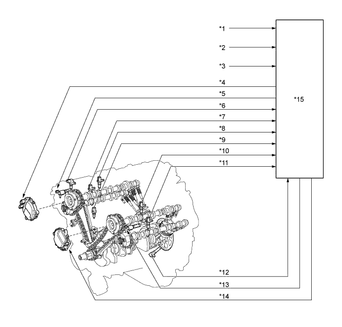
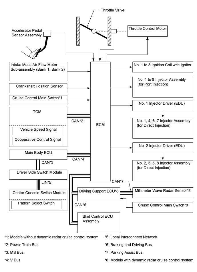
Text in Illustration *1 Intake Mass Air Flow Meter Sub-assembly (Bank 1, Bank 2) *2 Throttle Position Sensor *3 Vehicle Speed Signal *4 Camshaft Control Motor (Bank 2) *5 Camshaft Timing Oil Control Valve (Bank 2) *6 Camshaft Position Sensor *7 Exhaust VVT Sensor (Bank 2) *8 Intake VVT Sensor (Bank 2) *9 Engine Coolant Temperature Sensor *10 Intake VVT Sensor (Bank 1) *11 Exhaust VVT Sensor (Bank 1) *12 Crankshaft Position Sensor *13 Camshaft Timing Oil Control Valve (Bank 1) *14 Camshaft Control Motor (Bank 1) *15 ECM - - 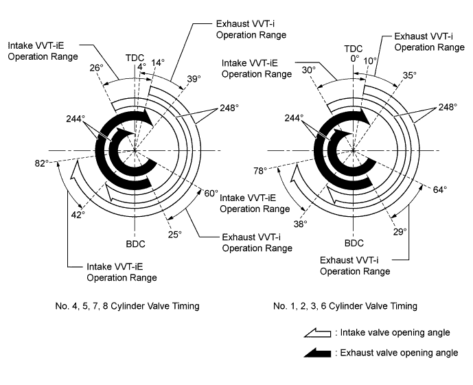
-
The Dual VVT-i system delivers excellent benefits in the different operating condition as follows:
-
During Idling

Objective Effect Eliminating overlap to reduce blowback to the intake side.
-
Stabilized idling speed
-
Better fuel economy
-
-
In Low Speed Range with Light to Medium Load

Objective Effect Retarding the intake valve close timing and reducing pumping loss, increasing overlap and increasing internal EGR.
-
Better fuel economy
-
Improved emission control
-
-
In Low to Medium Speed Range with Heavy Load

Objective Effect Advancing the intake valve close timing, reducing intake air blowback to the intake side and improving volumetric efficiency. Improved torque in low to medium speed range -
In High Speed Range with Heavy Load

Objective Effect Retarding the intake valve close timing and improving volumetric efficiency using the inertia force of the intake air. Improved output -
At Low Temperatures
Objective Effect Eliminating overlap to reduce blow back to the intake side, adjusting valve timing at extremely low temperatures and increasing the control range as the temperature rises.
-
Stabilized fast idle speed
-
Better fuel economy
-
-
Upon Starting
-
Stopping Engine
Objective Effect Controlling valve timing and adjusting it to the optimal timing for engine start. Improved startability
-
-
-
Electronic Throttle Control System-intelligent (ETCS-i)
-
In the conventional throttle body, the throttle valve angle is determined invariably by the amount of the accelerator pedal effort. In contrast, ETCS-i uses the ECM to calculate the optimal throttle valve angle that is appropriate for the respective driving condition and uses a throttle control motor to control the angle.
-
In case of an abnormal condition, this system switches to the limp mode.
-
-
Fuel Pump Control
-
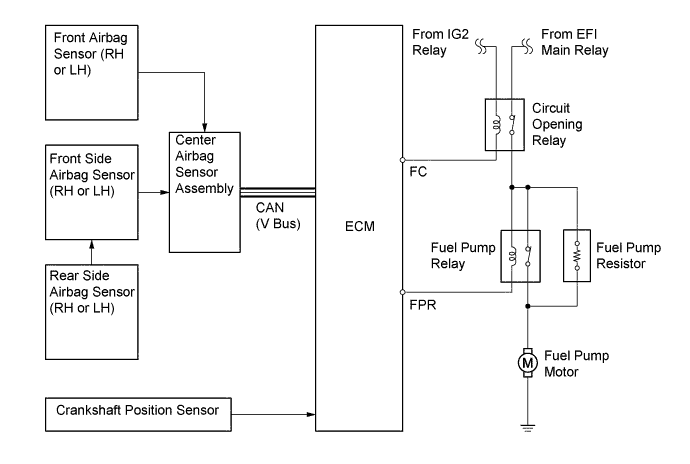
The fuel pump is controlled by the ECM, using the circuit opening relay.
-
The fuel pump control has a fuel cut control. The fuel cut control stops the fuel pump when any of the Supplemental Restraint System (SRS) airbags have deployed.
-
-
Cooling Fan Control
-
The cooling fan control system achieves an optimal fan speed in accordance with the engine coolant temperature, vehicle speed, engine speed, and air conditioning operating conditions.
-
-
Starter Control (Cranking Hold Function)
-
Once the engine switch is pressed, this function continues to operate the starter until the engine has started, provided that the brake pedal is depressed.
-
This prevents application of the starter for an inadequate length of time and also prevents the engine from being cranked after it has started.
-
-
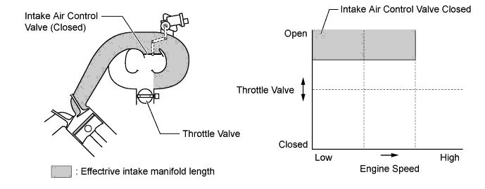
Acoustic Control Induction System (ACIS)
-
The ACIS uses a bulkhead to divide the intake manifold into 2 stages, with an intake air control valve in the bulkhead being opened and closed to vary the effective length of the intake manifold in accordance with the engine speed and throttle valve opening angle. This increases the power output in all ranges from low to high speed.
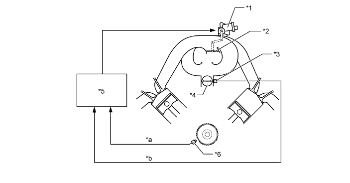
Text in Illustration *1 Actuator *2 Intake Air Control Valve *3 Throttle Position Sensor *4 Throttle Valve *5 ECM *6 Crankshaft Position Sensor *a Engine Speed Signal *b Throttle Valve Opening Angle
-
-
-
CONSTRUCTION
-
Intake Mass Air Flow Meter Sub-assembly
-
The intake mass air flow meter sub-assembly, which is a plug-in type, allows a portion of the intake air to flow through the detection area. By directly measuring the mass and the flow rate of the intake air, the detection precision is improved and the intake air resistance is reduced.
-
This intake mass air flow meter sub-assembly has a built-in intake air temperature sensor.
Text in Illustration *1 Platinum Hot-wire Element *2 Temperature Sensing Element *3 Intake Air Temperature Sensor - - 
Air Flow - -
-
-
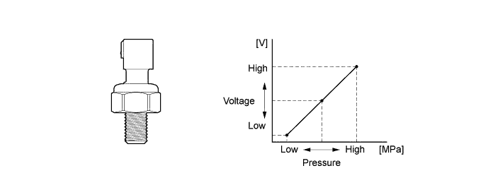
Fuel Pressure Sensor
-
The fuel pressure sensor, which is mounted on the delivery pipe, outputs a signal to the ECM that represents the fuel pressure in the delivery pipe in order to allow the constant regulation of the fuel at an optimal pressure.
-
-
Crankshaft Position, Camshaft Position and VVT Sensors
-
The Magnetic Resistance Element (MRE) sensors are used for the crankshaft position, camshaft position, and VVT sensors.
-
The timing rotor for the crankshaft position sensor is installed on the back end of the crankshaft. The timing rotor has 34 teeth, with 2 teeth missing, at 10° intervals. Based on these teeth, the crankshaft position sensor transmits crankshaft position signals (NE signal) consisting of 33 high and low output pulses every 10° per revolution of the crankshaft, and 1 high and low output pulse every 30°. The ECM uses the NE signal for detecting the crankshaft position as well as for detecting the engine speed. The ECM uses the missing teeth signal for determining the top dead center.
-
The camshaft position sensor uses a timing rotor that is installed on the front end of the intake camshaft sprocket of the right bank. Based on the timing rotor, the sensor outputs camshaft position signals (G2 signal) consisting of 6 (3 high output, 3 low output) pulses for every 2 revolutions of the crankshaft. The ECM compares the G2 and NE signals to detect the camshaft position and to identify the cylinder.
-
The intake and exhaust VVT sensors use timing rotors that are installed on the intake and exhaust camshafts of each bank. Based on the timing rotors, the sensors output VVT position signals consisting of 6 (3 high output, 3 low output) pulses for every 2 revolutions of the crankshaft. The ECM compares these VVT position signals to with NE signal to detect the actual valve timing.
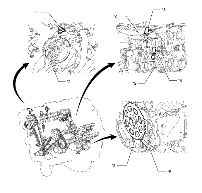
Text in Illustration *1 Camshaft Position Sensor *2 Timing Rotor *3 Intake VVT Sensor (Bank 1) *4 Exhaust VVT Sensor (Bank 1) *5 Crankshaft Position Sensor - - 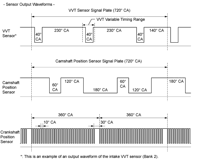
-
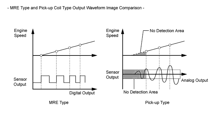
The MRE type sensor consists of an MRE, a magnet and a sensor.
-
The direction of the magnetic field changes due to the profile (protruding and non-protruding portions) of the timing rotor, which passes by the sensor. As a result, the resistance of the MRE changes, and the output voltage to the ECM changes to high or low. The ECM detects the crankshaft and camshaft positions based on this output voltage.
-
The differences between the MRE type sensor and the pick-up coil type sensor used on the conventional models are as follows:
-
The MRE type sensor outputs a constant level of high and low digital signals regardless of the engine speed. Therefore, the MRE type sensor can detect the positions of the crankshaft and camshaft at an early stage of cranking.
-
The pick-up coil type sensor outputs analog signals with levels that change with the engine speed.
-
-
-
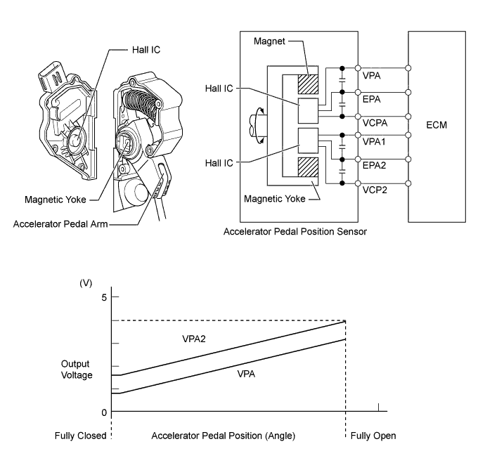
Accelerator Pedal Sensor Assembly
-
This non-contact type accelerator pedal position sensor uses a Hall IC which is mounted on the accelerator pedal arm.
-
A magnetic yoke is mounted at the base of the accelerator pedal arm. This yoke rotates around the Hall IC in accordance with the amount of effort that is applied to the accelerator pedal. The Hall IC converts the changes in the magnetic flux that occur into electrical signals, and outputs them in the form of accelerator pedal position signals to the ECM.
-
This accelerator pedal position sensor includes 2 Hall ICs and circuits for the main and sub signals. It converts the accelerator pedal depressed angles into electric signals with two differing characteristics and outputs them to the ECM.
-
-
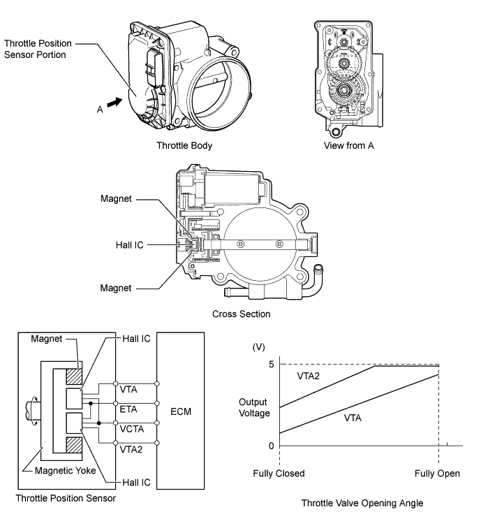
Throttle Position Sensor
-
A non-contact type throttle position sensor is used. This sensor uses a Hall IC which is mounted on the throttle body.
-
The Hall IC is surrounded by a magnetic yoke. The Hall IC converts the changes that occur in the magnetic flux into electrical signals and outputs them as throttle valve effort to the ECM.
-
The Hall IC contains circuits for the main and sub signals. It converts the throttle valve opening angles into electric signals with two differing characteristics and outputs them to the ECM.
-
-
Injector Driver (EDU)
-
The 1UR-FSE engine is provided with 2 injector drivers (Electronic Driver Units: EDUs) to control the injectors. One injector driver (EDU) controls the injectors (for direct injection) of the number 1, 4, 6 and 7 cylinders and the fuel pump spill control valve (for high pressure) on the left bank. The other injector driver (EDU) controls the injectors (for direct injection) of the number 2, 3, 5 and 8 cylinders and the fuel pump spill control valve (for high pressure) on the right bank.
-
The use of a DC/DC converter that converts 12 V into 50 V enables the injector drivers (EDUs) to operate the fuel injectors under high-pressure conditions. The DC/DC converter provides the injector drivers (EDUs) with a high-voltage, quick-charging system (the "quick-charging system" refers to the ability of the injector drivers (EDUs) to "recharge" their internal high-voltage power source).
-
The ECM constantly monitors the injector drivers (EDUs) and stops the engine in the event an abnormal condition is detected.
-
-
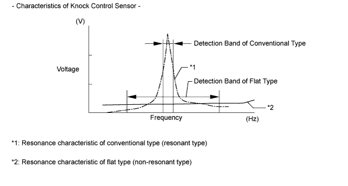
Knock Control Sensor (Flat Type)
-
In a conventional type knock control sensor (resonant type), a vibration plate is built into the sensor. This plate has the same resonance point as the knocking* frequency of the engine block. This sensor can only detect vibration in this frequency band.
-
*: The term "knock" or "knocking" is used in this case to describe either preignition or detonation of the air fuel mixture in the combustion chamber. This preignition or detonation refers to the air fuel mixture being ignited earlier than is advantageous. This use of "knock" or "knocking" is not primarily used to refer to a loud mechanical noise that may be produced by an engine.
-
-
A flat type knock control sensor (non-resonant type) has the ability to detect vibration in a wider frequency band (from approximately 6 kHz to 15 kHz). The sensor has the following features:
-
The engine knocking frequency will vary slightly depending on the engine speed. The flat type knock control sensor can detect vibration even when the engine knocking frequency changes. Due to the use of the flat type knock control sensor, the vibration detection ability has been increased compared to a conventional type knock control sensor, and more precise ignition timing control is possible.
-
-
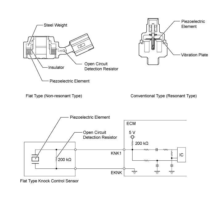
A flat type knock control sensor is installed on the cylinder block using the flange bolt. For this reason, a hole for the flange bolt exists in the center of the sensor.
-
In the sensor, a steel weight is located in the upper portion. An insulator is located between the weight and the piezoelectric element.
-
An open/short circuit detection resistor is integrated in the sensor. When the power switch is on (IG), the open/short circuit detection resistor in the knock control sensor and the resistor in the ECM keep the voltage at terminal KNK1 constant. An Integrated Circuit (IC) in the ECM constantly monitors the voltage of terminal KNK1. If the open/short circuit occurs between the knock control sensor and the ECM, the voltage of terminal KNK1 will change and the ECM will detect the open/short circuit and store a Diagnostic Trouble Code (DTC).
-
Vibrations caused by knocking are transmitted to the steel weight. The inertia of this weight applies pressure to the piezoelectric element. This action generates electromotive force.
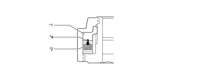
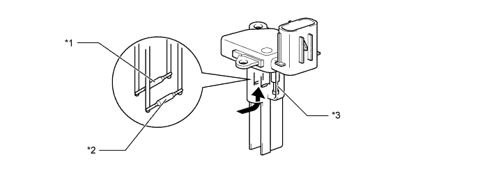
Text in Illustration *1 Steel Weight *2 Piezoelectric Element *a Inertia - - -
These knock control sensors are mounted in the specific directions and angles. To prevent the right and left bank connectors from being interchanged, make sure to install each sensor in its prescribed direction. For details, refer to the Repair Manual.
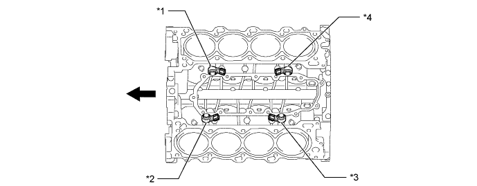
Text in Illustration *1 Knock Control Sensor (Bank 2, Sensor 1) *2 Knock Control Sensor (Bank 1, Sensor 1) *3 Knock Control Sensor (Bank 1, Sensor 2) *4 Knock Control Sensor (Bank 2, Sensor 2) Engine Front - -
-
-
Air Fuel Ratio Sensor and Oxygen Sensor
-
A planar type air fuel ratio sensor and a cup type oxygen sensor are used. The basic construction of the oxygen sensor and the air fuel ratio sensor is the same. However, they are divided into the cup type and the planar type in accordance with the different types of heater construction used.
-
The planar type air fuel ratio sensor uses alumina, which excels in heat conductivity and electrical insulation, to integrate the sensor element with a heater, thus improving the warmup performance of the sensor.
-
The cup type oxygen sensor contains a sensor element that surrounds the heater.
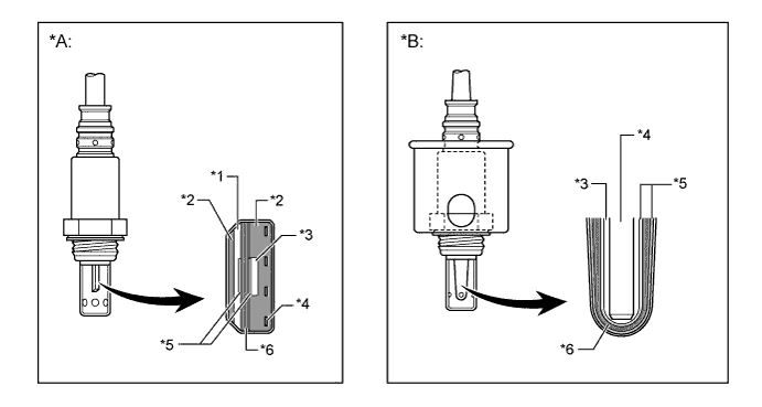
Text in Illustration *A Planar Type Air Fuel Ratio Sensor *B Cup Type Oxygen Sensor *1 Diffusion Resistance Layer *2 Alumina *3 Atmosphere *4 Heater *5 Platinum Electrode *6 Sensor Element (Zirconia) -
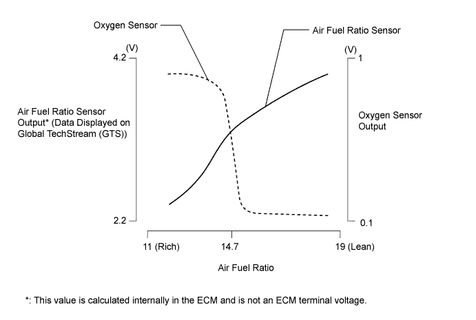
As illustrated below, the conventional oxygen sensor is characterized by a sudden change in its output voltage at the threshold of the stoichiometric air fuel ratio (14.7:1). In contrast, the air fuel ratio sensor data is approximately proportionate to the existing air fuel ratio. The air fuel ratio sensor converts the oxygen density to current and sends it to the ECM. As a result, the detection precision of the air fuel ratio has been improved. The air fuel ratio sensor data can be viewed using a Global TechStream (GTS).
-
-
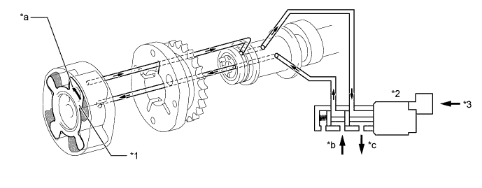
Camshaft Timing Oil Control Valve
-
This camshaft timing oil control valve controls the spool valve using duty cycle control from the ECM. This allows engine oil pressure to be applied to the VVT-i controller advance or retard side. When the engine is stopped, the camshaft timing oil control valve is in the most advanced position.
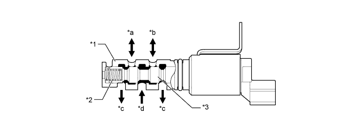
Text in Illustration *1 Sleeve *2 Spring *3 Spool Valve - - *a To VVT-i Controller (Advance Side) *b To VVT-i Controller (Retard Side) *c Drain *d Oil Pressure
-
-
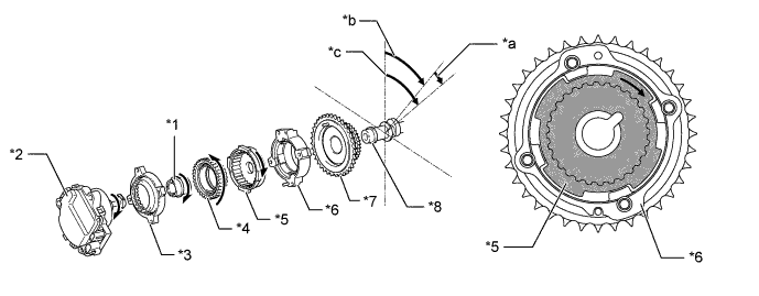
Camshaft Control Actuator
-
The camshaft control actuator rotates the intake camshaft to the advance side or retard side, and consists of a 2-stage cycloid reduction unit which reduces the rotation speed of the camshaft control motor.
-
The rotation of the camshaft control motor rotates the planetary gear via the cycloid reduction unit. By rotating the planetary gear, the intake camshaft fixed into the camshaft gear is rotated to the advance side or retard side.
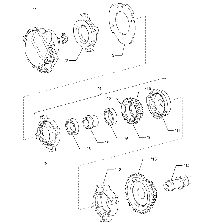
Text in Illustration *1 Camshaft Control Motor *2 Boss Weight *3 Signal Rotor *4 Cycloid Reduction Unit *5 Sprocket Gear *6 Bearing *7 Eccentric Shaft *8 Large Gear *9 Planetary Gear *10 Small Gear *11 Camshaft Gear *12 Housing *13 Sprocket *14 Intake Camshaft -
The cycloid reduction unit consists of a sprocket gear, an eccentric shaft, a planetary gear and a camshaft gear.
-
The eccentric shaft has a circular shape, which is eccentric in relation to the rotation axis of the camshaft, and connects with the sprocket gear.
-
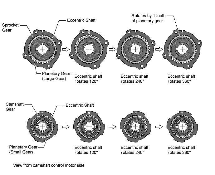
The sprocket gear has 1 tooth more than the large gear of the planetary gear, and the small gear of the planetary gear has 1 tooth less than the camshaft gear.
-
Through the eccentric movement of the eccentric shaft, the planetary gear rotates while meshing with the sprocket gear and camshaft gear.
-
When the eccentric shaft rotates once, the planetary gear moves while meshing with the sprocket gear, and rotates by 1 tooth only. The rotations that are decelerated by the cycloid reduction unit cause the intake camshaft to rotate.
-
-
Camshaft Control Motor
-
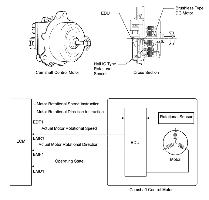
The camshaft control motor consists of a motor that operates the camshaft control actuator in the advance or retard direction, an EDU that controls the rotational condition of the motor and a Hall IC type rotational sensor that detects the rotational condition of the motor.
-
The motor is a brushless type DC motor that is installed in the engine front cover in front of the camshaft control actuator. The motor rotates coaxially with the intake camshaft.
-
In accordance with the target valve timing, the ECM transmits the motor rotational speed instruction signals and the motor rotational direction instruction signals to the EDU. Based on these signals, the EDU drives the motor to rotate the intake camshaft in the advance or retard direction.
-
The EDU always monitors the motor operating condition and transmits the actual motor rotational speed signals, the actual motor rotational direction signals and the operating state signals to the ECM. The ECM uses these signals to diagnose malfunctions.
-
-
Ignition Coil Assembly
-
The DIS provides 8 ignition coil assemblies, one for each cylinder. The spark plug caps, which provide contact to spark plugs, are integrated with the ignition coil. Also, the ignition are enclosed to simplify the system.
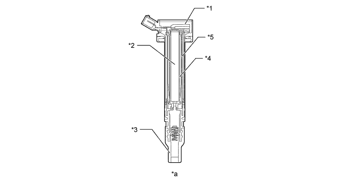
Text in Illustration *1 Igniter *2 Iron Core *3 Plug Cap *4 Secondary Coil *5 Primary Coil - - *a Ignition Coil Cross Section - -
-
-
Spark Plug
-
Long-reach type spark plugs are used. This type of spark plug allows the area of the cylinder head which receives the spark plugs to be made thick. Thus, the water jacket can be extended near the combustion chamber, which contributes to cooling performance.
-
The triple ground electrode type iridium-tipped spark plugs are used to achieve a 193000 km (120000 miles) maintenance interval. By making the center electrode if iridium, it is possible to plugs. Furthermore, 2 ground electrodes have been added to further improve ignitability, wear resistance, and fouling resistance.
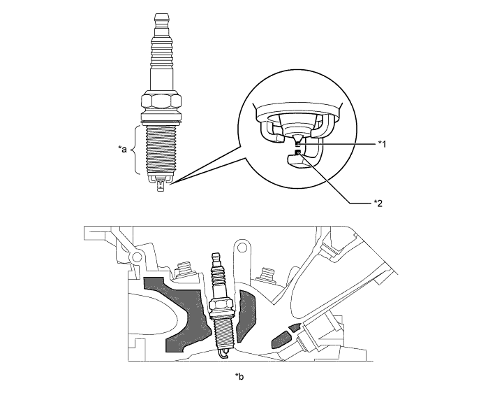
Text in Illustration *1 Iridium Tip *2 Platinum Tip *a Long-reach *b Cylinder Head Cross Section 
Water Jacket - -
-
-
-
OPERATION
-
Dual VVT-i System
-
VVT-iE
-
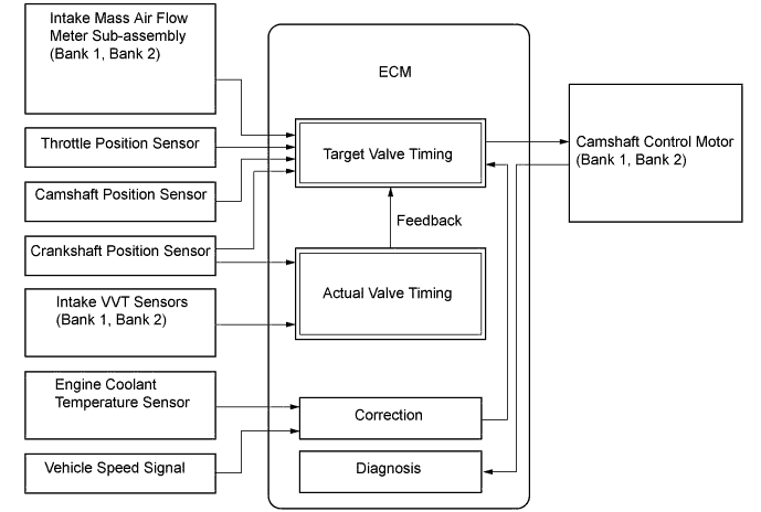
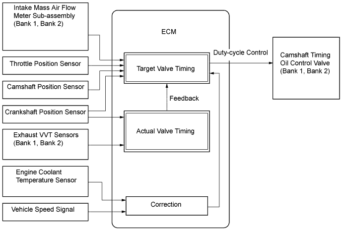
The VVT-iE consists of camshaft control actuators that rotate the intake camshafts via a link mechanism and EDU-integrated camshaft control motors that operate the link mechanism in accordance with the signals received from the ECM.
-
Based on engine speed, intake air mass, throttle position, vehicle speed and engine coolant temperature, the ECM calculates optimal valve timing for all driving conditions. The ECM uses the calculated valve timing as the target valve timing to control the camshaft control motors. In addition, the ECM uses signals from the intake VVT sensors and the crankshaft position sensor to detect the actual valve timing, thus providing feedback control to achieve the target valve timing.
-
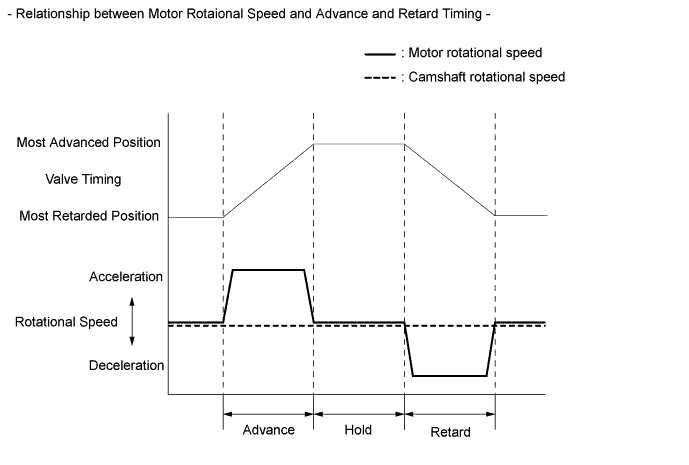
The ECM controls the advance and retard operation by way of the rotational speed difference between the motor and the camshaft. The ECM maintains the valve timing by rotating the motor at the same rotational speed as the camshaft.
-
To advance, the motor rotational speed becomes faster than the camshaft rotational speed.
-
To retard, the motor rotational speed becomes slower than the camshaft rotational speed. (The motor turns clockwise and counterclockwise in accordance with engine conditions.)
-
As the advance signals from the ECM cause the motor to rotate faster than the camshaft, the camshaft gear rotates in the direction shown in the illustration via the reduction unit. This rotation causes the intake camshaft coupled with the camshaft gear to rotate in the advance direction.
Text in Illustration *1 Eccentric Shaft *2 Camshaft Control Motor *3 Sprocket Gear *4 Planetary Gear *5 Camshaft Gear *6 Housing *7 Sprocket *8 Intake Camshaft *a Advance Side *b Sprocket Speed *c Camshaft Speed - - -
As the retard signals from the ECM cause the motor to rotate slower than the camshaft, the camshaft gear rotates in the direction shown in the illustration via the reduction unit. This rotation causes the intake camshaft coupled with the camshaft gear to rotate in the retard direction. The motor turns clockwise and counterclockwise in accordance with engine conditions.
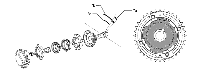
Text in Illustration *a Retard Side *b Sprocket Speed *c Camshaft Speed - - -
After the target valve timing has been reached, the ECM rotates the motor at the same rotational speed as the camshaft. As a result, the camshaft control actuator becomes locked, thus holding the camshaft at the valve timing.
-
-
VVT-i
-
The VVT-i consists of VVT-i controllers that are operated by engine oil pressure and camshaft timing oil control valves that switch the engine oil pressure passages in accordance with the signals from the ECM.
-
Based on engine speed, intake air mass, throttle position, vehicle speed and engine coolant temperature, the ECM calculates optimal valve timing for all driving conditions. The ECM uses the calculated valve timing as the target valve timing to control the camshaft timing oil control valves. In addition, the ECM uses signals from the exhaust VVT sensors and the crankshaft position sensor to detect the actual valve timing, thus providing feedback control to achieve the target valve timing.
-
When the camshaft timing oil control valve is positioned as illustrated below by the advance signals from the ECM, the resultant oil pressure is applied to the timing advance side vane chamber to rotate the camshaft in the timing advance direction.
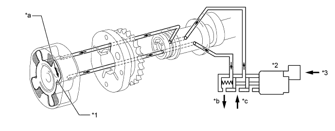
Text in Illustration *1 Vane *2 Camshaft Timing Oil Control Valve *3 ECM - - *a Rotation Direction *b Drain (Oil Pressure) *c In (Oil Pressure) - - -
When the camshaft timing oil control valve is positioned as illustrated below by the retard signals from the ECM, the resultant oil pressure is applied to the timing retard side vane chamber to rotate the camshaft in the timing retard direction.
Text in Illustration *1 Vane *2 Camshaft Timing Oil Control Valve *3 ECM - - *a Rotation Direction *b In (Oil Pressure) *c Drain (Oil Pressure) - - -
After reaching the target timing, the valve timing is held by keeping the camshaft timing oil control valve in the neutral position unless the traveling state changes.
-
This adjusts the valve timing at the desired target position and prevents the engine oil from running out.
-
-
-
ACIS
-
While the engine is running at low-to-medium speed under heavy load, the ECM causes the actuator to close the control valve. As a result, the effective length of the intake manifold is lengthened and the intake efficiency in the low-to-medium speed range is improved due to the dynamic effect (inertia) of the intake air, thereby increasing power output.
-
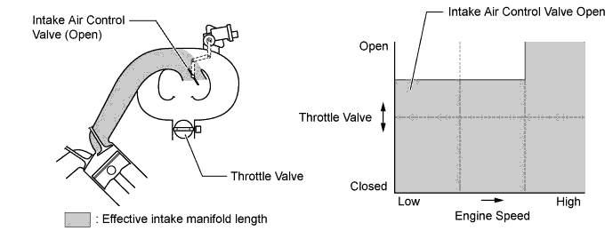
Under any condition except when the engine is running at low-to-medium speed under heavy load, the ECM causes the actuator to open the control valve. When the control valve is open, the effective length of the intake air chamber is shortened and peak intake efficiency is shifted to the low-to-high engine speed range, thus providing greater output at low-to-high engine speeds.
-
-
ETCS-i
-
The ECM drives the throttle control motor by determining the target throttle valve opening in accordance with the respective operating condition as follows:
-
Controls the throttle to an optimal throttle valve angle that is appropriate for the driving condition such as the amount of the accelerator pedal effort and the engine speed in order to realize excellent throttle control and comfort in all operating ranges.
-
In situations in which low-μ (low friction) road surface conditions can be anticipated, such as when driving in the snow, the rate of throttle valve opening can be controlled to help vehicle stability while driving on the slippery surface. This is accomplished by turning on SNOW mode. Pressing the SNOW side of the pattern select switch activates this mode. This mode modifies the relationship and reaction of the throttle to the accelerator pedal, and assists the driver by reducing the engine output from that of a normal level.
-
The ECM controls the throttle valve in order to constantly maintain an ideal idle speed.
-
The ECM effects cooperative control with the TCM in order to control the throttle valve at a position that is optimal for the driving conditions. Thus, it ensures a quick response to the driver's accelerator pedal effort and reduces shift shocks.
-
As part of the TRC function, the throttle valve is closed by a demand signal from the skid control ECU if an excessive amount of slippage is created at a driving wheel, thus facilitating the vehicle in ensuring excellent vehicle stability and driving force.
-
In order to bring the effectiveness of the VSC function control into full play, the throttle valve angle is controlled by effecting a coordination control with the skid control ECU.
-
An ECM with an integrated cruise control ECU directly actuates the throttle valve for operation of the cruise control.
-
The dynamic radar cruise control uses a millimeter wave radar sensor and the driving support ECU to determine the distance of the vehicle driven ahead, its direction, and relative speed. Thus, the system can effect deceleration cruising control, follow up cruising control, cruising at a fixed speed control, and acceleration cruising control. To make these controls possible, the ECM controls the throttle valve. (Models with dynamic radar cruise control system)
-
-
Fuel Pump Control
-
A fuel cut function is used to stop the fuel pump once when any of the SRS airbags have deployed. In this system, the airbag deployment signal from the airbag sensor assembly is detected by the ECM, and the ECM turns off the circuit opening relay. After the fuel cut function has been activated, turning the power source from off to on (IG) cancels the fuel cut function, and the engine can be restarted.
-
The ECM uses the fuel pump relay and the fuel pump resistor to control the fuel pump speed in accordance with driving conditions.
-
-
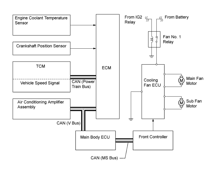
Cooling Fan Control System
-
A cooling fan control system is used. To achieve an optimal fan speed in accordance with the engine coolant temperature, engine speed, vehicle speed, and air conditioning operating conditions, the ECM calculates an appropriate fan speed and sends signals to the cooling fan ECU via the main body ECU and the front controller. Upon receiving the signals from the ECM, the cooling fan ECU actuates the fan motors.
-
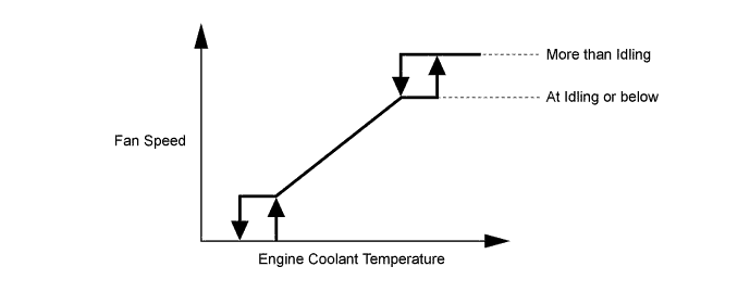
The ECM controls the cooling fan speed in accordance with the value of the engine coolant temperature as shown in the graph below. When the engine coolant temperature is higher than a specific value, the control differs depending on whether the engine speed is above idling speed, or is at idling speed or below.
-
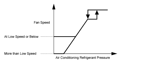
The ECM controls the cooling fan speed in accordance with the value of the air conditioning refrigerant pressure as shown in the graph below. When the air conditioning refrigerant pressure is higher than a specific value, the control differs depending on whether the engine speed is above a low speed, or is at a low speed or below.
-
-
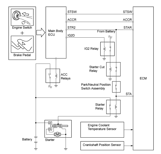
Starter Control (Cranking Hold Function)
-
When the ECM detects a start signal from the main body ECU, the system monitors the engine speed (NE signal) and continues to operate the starter until it has determined that the engine has started. Furthermore, even if the ECM detects a start signal from the main body ECU, the system will not operate the starter if the ECM has determined that the engine has already started.
-
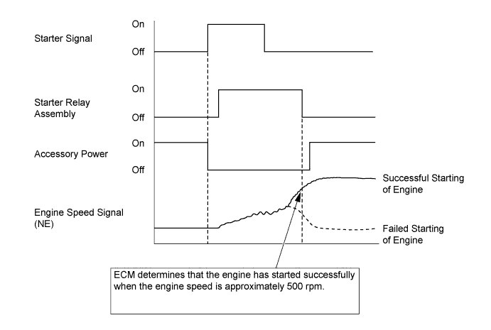
As indicated in the timing chart below, when the ECM detects as STSW signal (start signal) from the main body ECU, the ECM outputs a STAR signal (starter relay drive signal) through the starter cut relay to the starter relay and actuates the starter. The ECM also outputs an ACCR signal (ACC cut request signal) to the main body ECU. As a result, the main body ECU does not energize the ACC relay.
-
After the starter operates and the engine speed becomes higher than approximately 500 rpm, the ECM determines that the engine has started and stops the output of the STAR signal to the starter relay and the output of ACCR signal to the main body ECU. As a result, the starter operation stops and the main body ECU energizes the ACC relay.
-
If the engine has any failure and does not start, the starter operates as long as its maximum continuous operation time and stops automatically. The maximum continuous operation time is approximately 5 seconds through 25 seconds depending on the engine coolant temperature condition. When the engine coolant temperature is extremely low, the maximum continuous operation time is approximately 25 seconds and when the engine is warmed up sufficiently, it is approximately 5 seconds.
-
This system cuts off the current that powers the accessories while the engine is cranking to prevent the accessory illumination from operating intermittently due to the unstable voltage that is associated with the cranking of the engine.
-
This system has following protection features:
-
While the engine is running normally, the starter does not operate.
-
Even if the driver keeps pressing the engine switch, the ECM stops the output of the STAR and ACCR signals when the engine speed becomes higher than 1200 rpm. Thus, the starter operation stops and the main body ECU energize, the ACC relay.
-
If the driver keeps pressing the engine switch and the engine does not start, the ECM stops the output of the STAR and ACCR signals after 30 seconds have elapsed. Thus, the starter operation stops and the main body ECU energize, the ACC relay.
-
If the ECM cannot detect an engine speed signal while the starter is operating, the ECM immediately stops the output of the STAR and ACCR signals. Thus, the starter operation stops and the main body ECU energize, the ACC relay.
-
-
-