BODY STRUCTURE DETAILS
-
FUNCTION
-
Safety Features
-
Impact Absorbing Structure for Frontal Collision
-
Through the adoption of a body structure that disperses collision energy to multiple frame components, collision energy is efficiently absorbed to suppress cabin deformation.
-
The front side members utilize to absorb and disperse energy in a frontal collision.
-
Door beltline reinforcements are strengthened to optimize dispersal of collision energy to the rocker panel and floor panel.
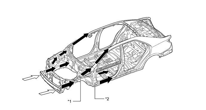
Text in Illustration *1 Front Side Member *2 Beltline Reinforcement 
Impact 
Impact Flow
-
-
Impact Absorbing Structure for Side Collision
-
Ultra high tensile strength steel is used for the center pillar outer reinforcement, center pillar beltline reinforcement, center pillar hinge reinforcement, rocker panel inner reinforcement and rocker panel outer reinforcement to ensure high strength.
-
Bulkheads are placed on both sides of floor cross members and center floor side crossmember to efficiently transmit impact load from the impact beam to the floor crossmembers.
-
The use of roof reinforcement enables a construction that transmits load to the opposite side of the vehicle in a collision.
-
Optimal placement of the impact protect beam enables a construction that efficiently transmits load.
-
The impact support box is optimally placed on the front floor between the front driver's seat and front passenger's seat to ensure that load is transmitted from the center pillar to the seat pipe, impact support box, and seat pipe on the opposite side, thus helping secure sufficient survival space.
-
A rear door box is provided inside the bottom of the rear door. In the event of a side collision, the rear door box strikes the rear crossmember gusset, absorbing the impact by transmitting it to the center floor member.
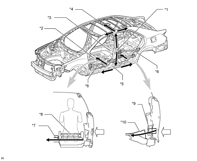
Text in Illustration *1 Center Pillar Outer Reinforcement *2 Front Floor Crossmember *3 Center Floor Crossmember *4 Roof Reinforcement *5 Rocker Panel Reinforcement *6 Impact Protect Beam *7 Impact Support Box *8 Seat Pipe *9 Rear Door Box *10 Center Crossmember Gusset Impact Impact Flow -
When the roof is subjected to an impact, the impact is dispersed to the roof reinforcements, front pillars and center pillars, thereby minimizing deformation of the cabin.
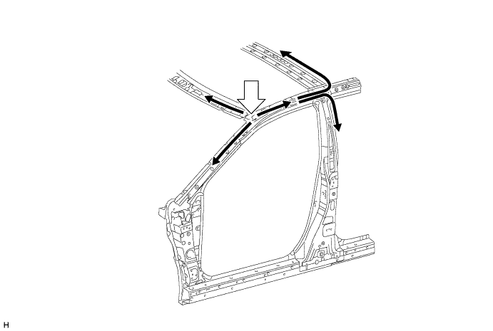
Text in Illustration Impact Impact Flow
-
-
Impact Absorbing Structure for Rear Collision
-
Straight rear side members are used to reduce body deformation in a rear collision.
-
-
Lessening Pedestrian Injury
-
A hood reinforcement is provided for the hood inner panel to help secure excellent pedestrian protection performance and tensile rigidity.
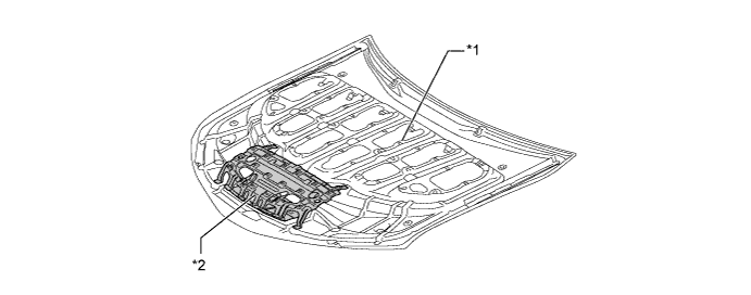
Text in Illustration *1 Longitudinal Ribbed Structure *2 Dent Reinforcement (Impact Absorbing Structure) -
An impact absorbing bracket is used for the mounting portion of the front fender panel to absorb impact energy to the head of the pedestrian in a collision, thus dampening the impact to the head.
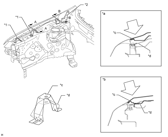
Text in Illustration *1 Impact Absorbing Bracket (Front) *2 Impact Absorbing Bracket (Rear) *a A-A Cross Section *b B-B Cross Section *c Before Collision *d After Collision Impact - - -
The cowl uses an open section structure that collapses easily in an impact from the top, thus reducing the impact to and head injuries sustained by a pedestrian in an accident.
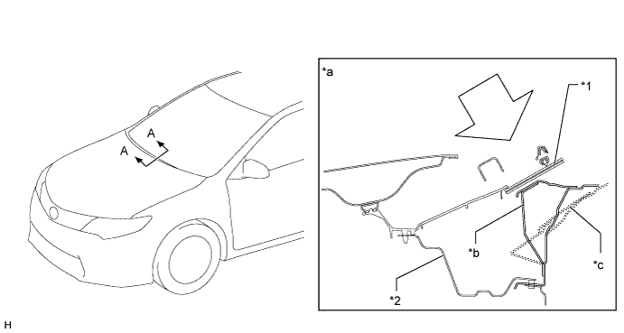
Text in Illustration *1 Window Shield Glass *2 Cowl Top Panel Sub-assembly *a A-A Cross Section *b Before Collision *c After Collision - - Impact - -
-
-
-
Aerodynamics
-
An aero stabilizing fin is provided on the outer rear view mirror base and on the rear combination light lens for enhanced aerodynamics.
-
After passing the aero stabilizing fin, the air speed will increase and vortex flow will be generated.
-
This vortex flow increases the speed of surrounding air while at the same time pulling the airflow towards the vehicle body.
-
The airflow with higher speed passes near both sides of the vehicle body and ends at the rear of the vehicle. This helps to hold the vehicle body, and thus stabilizes the vehicle.
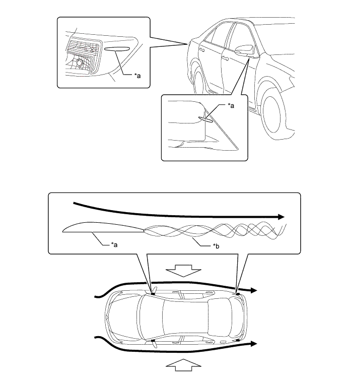
Text in Illustration *a Aero Stabilizing Fin *b Vortex Airflow Hold the Vehicle from Both Side -
-
The height, angle, and shape of the front bumper have been optimized, resulting in smooth airflow underneath the floor.
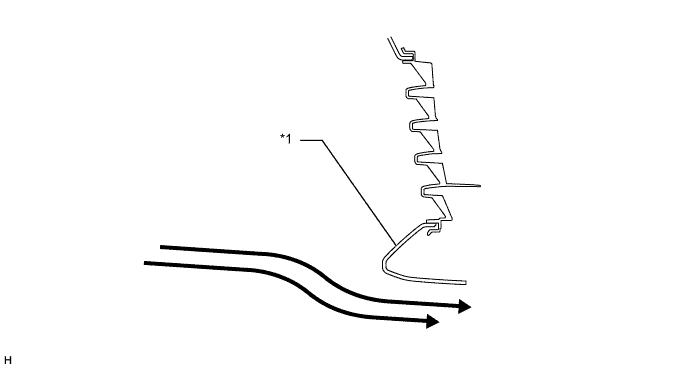
Text in Illustration *1 Front Bumper - - Airflow - - -
Various types of airflow routing parts are provided under the floor to control airflow. In addition, an undercover is provided to make the under floor area flat in order to ensure excellent aerodynamic performance.
-
A fin-shaped engine under cover and rear under cover have been adopted to achieve higher diffuser efficiency, thereby ensuring stability.
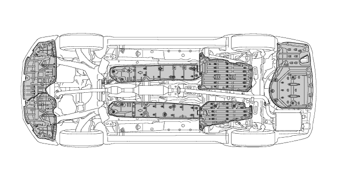
Text in Illustration 
Undercover Area - -
-
-
-
CONSTRUCTION
-
Lightweight and Highly Rigid Body
-
High strength steel and ultra high strength steel are used in order to realize excellent body rigidity and a lightweight body.
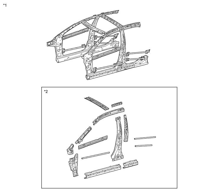
Text in Illustration *1 High Strength Steel *2 Ultra High Strength Steel
-
-
Rust-resistant Body
-
Anti-corrosion steel sheet is used as shown in the following illustration:
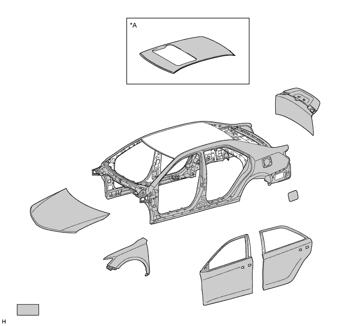
Text in Illustration (Upper Body:) *A Models with Roof Sliding System - - Anti-corrosion Steel Sheet - - -
For rust resistance, sealant has been applied to the floor panel to prevent water from entering through the mating surfaces of the panels. Undercoating has been also applied to reduce damage to the body from chipping, contributing to rust resistance.
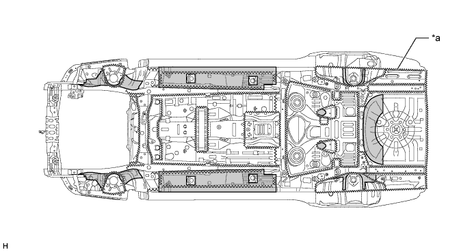
Text in Illustration (Under Body:) *a Sealant - - Under Coat - -
-
-
Body Shell Construction
-
The cowl top panel sub-assembly outer is used to connect the left and right front spring supports , which is straight, improving lateral rigidity and ensuring front suspension input point rigidity and body rigidity.
-
Sound absorbing material is used in engine room side of cowl top panel sub-assembly to reduce the amount of engine noise entering the vehicle cabin from the engine room.
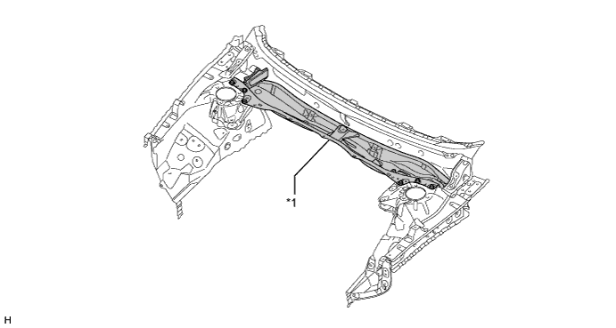
Text in Illustration *1 Cowl Top Panel Sub-assembly - - -
A closed shape has been adopted for the upper back panel. The upper back panel is used to connect the left and right back side panels, which is straight, improving light weight yet body rigidity.
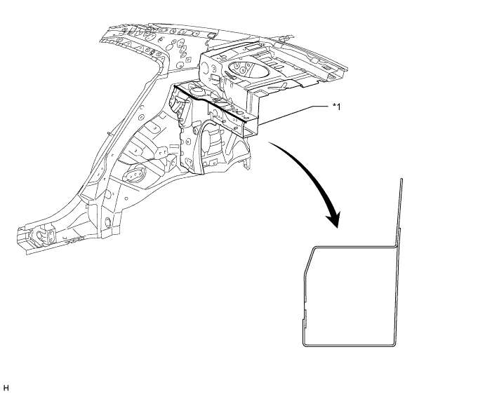
Text in Illustration *1 Under Back Panel - - -
Along with the optimal positioning of frame components such as rear side members, center floor members, rear floor crossmember and rear sub-frame the usage of a small number of parts has realized a lightweight design while also ensuring an excellent rigidity and handling stability.
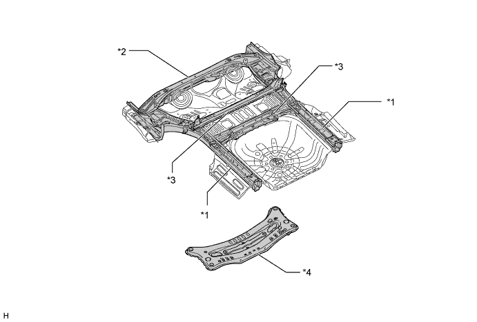
Text in Illustration *1 Rear Side Member *2 Center floor Crossmember *3 Rear floor Crossmember *4 Rear Sub-frame
-
-
Low Vibration and Low Noise Body
-
The following body structures are used, in order to reduce panel vibration and body frame movement.
Panel vibration reduction structure -
The cross member of the dash panel is provided
-
The tunnel reinforcement is connected to the floor
-
The floor pan panel rigidity has been improved
-
The floor pan bead layouts have been changed
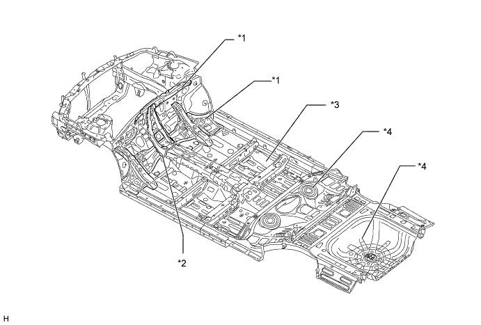
Text in Illustration *1 Cross Member of Dash Panel *2 Tunnel Reinforcement *3 Floor Pan Panel *4 Bead -
-
Damping coatings are provided, combining enhanced quietness and reduced weight.
Text in Illustration Damping Coating - - -
Silencer pads are provided on the engine compartment side and cabin side of the dash panel, minimizing penetration of engine noise and road noise into the cabin.
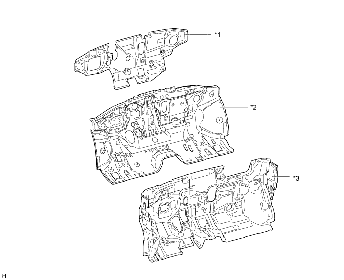
Text in Illustration *1 Dash Panel Insulator Outer *2 Dash Panel *3 Dash Panel Insulator Inner - - -
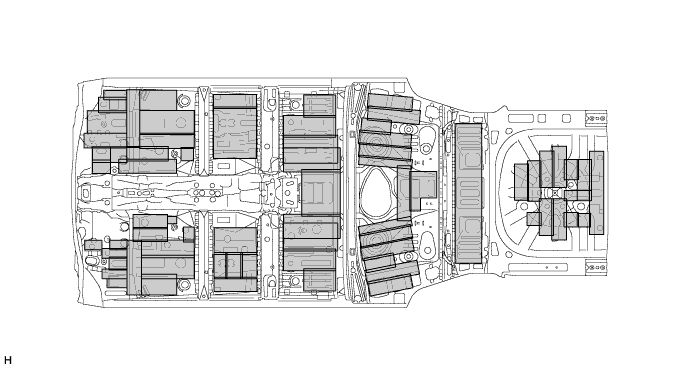
The layout of the sound-absorbing material is optimized to reduce noise and vibration.
Text in Illustration *a A-A Cross Section *b B-B Cross Section *c C-C Cross Section - - 
Sound-absorbing Material - - -
Sound absorbing material are used in the front fender liners to reduce road noise.
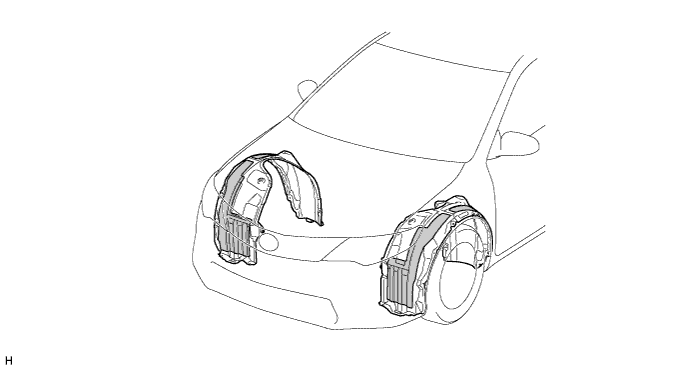
Text in Illustration Sound Absorbing Material - - -
Silencers are provided inside the rear wheel housings to minimize the penetration into the cabin of splashing noise generated in the wheel housings.
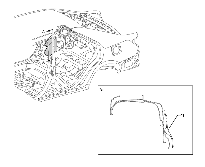
Text in Illustration *1 Rear Wheel House Silencer - - *a A-A Cross Section - - -
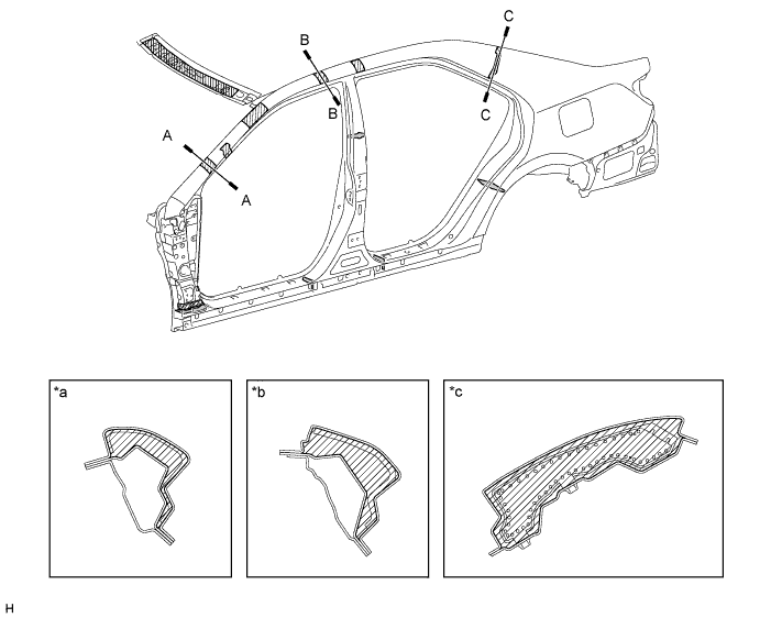
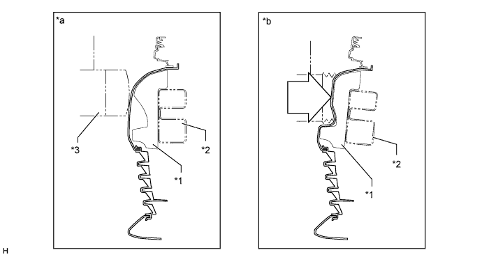
Weatherstrips are provided for the front and rear doors at the rocker panel to minimize the penetration of road noise into the cabin.
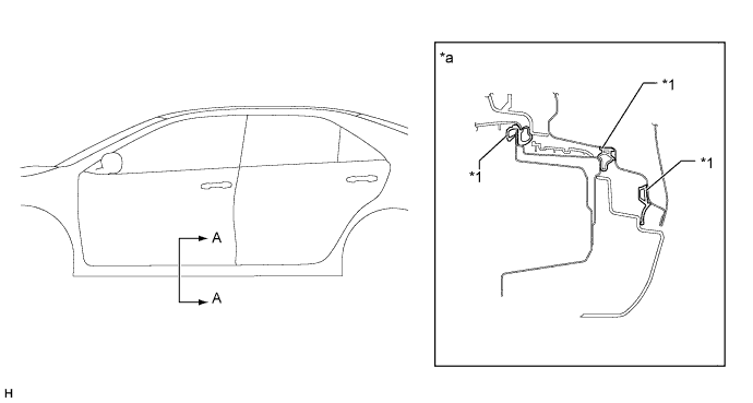
Text in Illustration *1 Weatherstrip - - *a A-A Cross Section - -
-
-
Parts that Reduce Overall Damage
-
A concave design has been adopted for the front bumper absorber. This helps prevent the vehicle from going under obstacles in the event of a collision.
Text in Illustration *1 Front Bumper Absorber *2 Front Bumper Reinforcement *3 Obstacles - - *a Before Collision *b After Collision
-
-