HYBRID TRANSAXLE SYSTEM DETAILS
-
SYSTEM CONTROL
-
Shift Control System
-
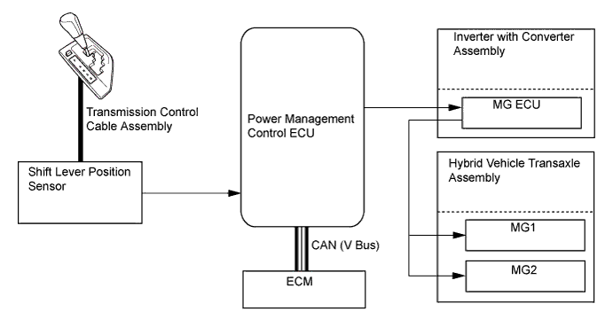
A shift lever position sensor is provided in the transaxle to detect the shift position and sends a corresponding signal to the power management control ECU. Upon receiving this signal, the power management control ECU optimally combines the operation of the engine, MG1 and MG2 in order to produce the respective shift positions (P, R, N, D and B).
-
-
-
CONSTRUCTION
-
Hybrid Vehicle Transaxle Assembly
-
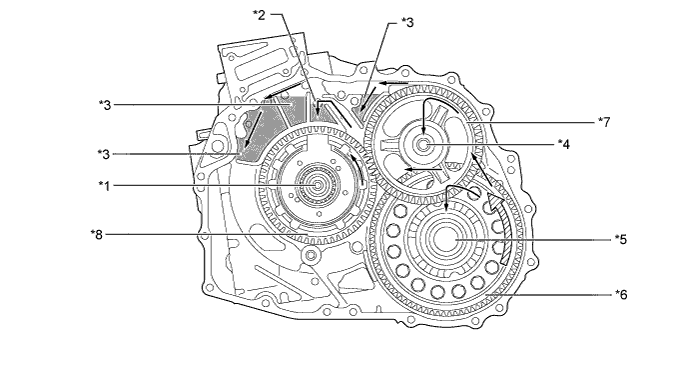
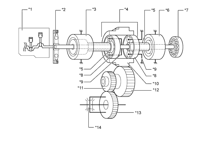
This hybrid vehicle transaxle assembly consists primarily of MG1, MG2, a compound gear unit, a transmission input damper assembly, a counter gear, a final gear, a differential gear unit and an oil pump.
-
This hybrid vehicle transaxle assembly has a 3-shaft configuration. The compound gear unit, a transmission input damper assembly, an oil pump, MG1 and MG2 are provided on the input shaft. The counter driven gear and the final drive gear are provided on the second shaft. The final driven gear and the differential gear unit are provided on the third shaft.
-
The engine, MG1 and MG2 are mechanically joined via the compound gear unit.
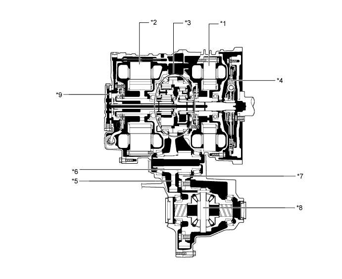
Text in Illustration *1 MG1 *2 MG2 *3 Compound Gear Unit *4 Transmission Input Damper Assembly *5 Counter Driven Gear *6 Final Drive Gear *7 Final Driven Gear *8 Differential Gear Unit *9 Oil Pump - -
-
-
Compound Gear Unit
-
The compound gear unit consists of the power split planetary gear unit and the motor speed reduction planetary gear unit. Each planetary ring gear is integrated with the compound gear. Furthermore, this compound gear is integrated with a counter drive gear and parking gear.
-
The power split planetary gear unit splits the motive force of the engine two ways: one to drive the wheels, and the other to drive MG1, so that MG1 can function as a generator.
-
The motor speed reduction planetary gear unit, whose purpose is to reduce MG2 speed, is used to enable the high-speed, high-output MG2 to adapt optimally to the compound gear.
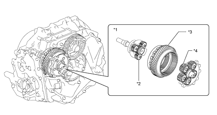
Text in Illustration *1 Compound Gear Unit *2 Power Split Planetary Gear Unit *3 Counter Drive Gear (Compound Gear) *4 Motor Speed Reduction Planetary Gear Unit -
The connection of the sun gear, ring gear and carrier of each planetary gear unit is as shown below.
Item Connection Power Split Planetary Gear Unit Sun Gear MG1 Ring Gear Compound Gear (To Wheels) Carrier Input Shaft (From Engine) Motor Speed Reduction Planetary Gear Unit Sun Gear MG2 Ring Gear Compound Gear (To Wheels) Carrier Fixed 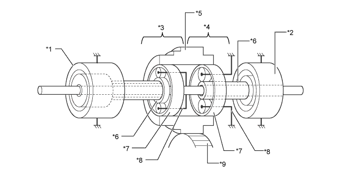
Text in Illustration *1 MG1 *2 MG2 *3 Power Split Planetary Gear Unit *4 Motor Speed Reduction Planetary Gear Unit *5 Counter Drive Gear *6 Sun Gear *7 Ring Gear *8 Carrier *9 Counter Driven Gear - -
-
-
Transmission Input Damper Assembly
-
A transmission input damper assembly that consists of a coil spring with low-twist characteristics is used in order to absorb the torque fluctuation in the motive force of the engine. The torque limiter uses a dry-type, single-plate friction material. Through the use of these parts, a damper construction that excels in absorbing the vibrations of the engine motive force has been achieved.
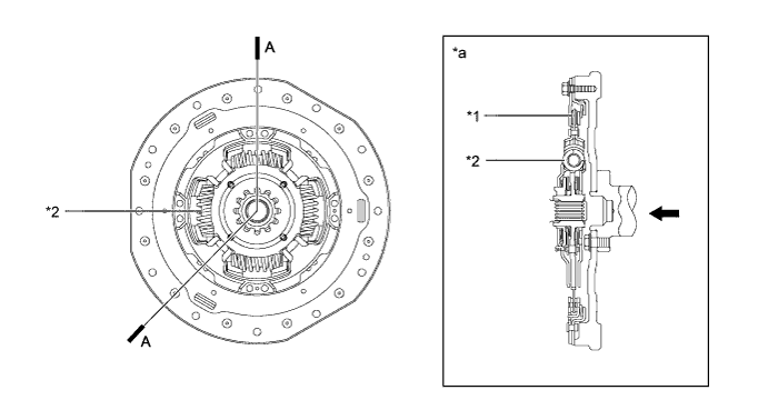
Text in Illustration *1 Torque Limiter *2 Coil Spring *a A-A Cross Section - - 
From Engine - -
-
-
Oil Pump Mechanism
-
The oil pump consists of the oil pump drive shaft, oil pump drive rotor, oil pump driven rotor and oil pump cover. The pump is driven by the engine via the input shaft and lubricates the gears.
Text in Illustration *1 Oil Pump Drive Shaft *2 Oil Pump Drive Rotor *3 Oil Pump Driven Rotor *4 Oil Pump Cover
-
-
Oil Sling Type Lubrication Mechanism
-
This sling type lubrication mechanism uses the oil catch tanks and final driven gear, which sling the lubricant into the oil catch tanks. This construction minimizes the drive torque of the oil pump, which reduces the drive loss.
-
The oil catch tanks are used in order to supply oil in a stable manner. The oil catch tanks temporarily store the oil that is slung up, and supply oil to the gears from there. Furthermore, oil holes are provided in the oil catch tanks in order to efficiently supply oil to MG1 and MG2.
Text in Illustration *1 Input Shaft *2 Oil Hole *3 Oil Catch Tank *4 Second Shaft *5 Third Shaft *6 Final Driven Gear *7 Counter Driven Gear *8 Counter Drive Gear Oil Flow 
Final Gear Rotation Direction
-
-
Shift Lever Position Sensor
-
The shift lever position sensor sends the P, R, N, D and B position signals to the power management control ECU.
-
The power management control ECU transmits signals to the combination meter assembly for the shift indicator lights (P, R, N, D and B) in response to the signals received from the sensor.
-
-
Parking Lock Mechanism
-
The parking lock mechanism consists of a parking lock pawl and a parking gear which is integrated with the compound gear.
-
When the driver moves the shift lever to P, the parking lock pawl engages with the parking lock gear.
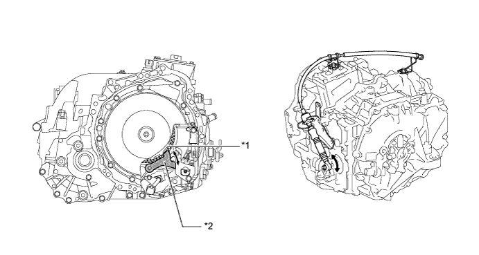
Text in Illustration *1 Parking Lock Gear *2 Parking Lock Pawl
-
-
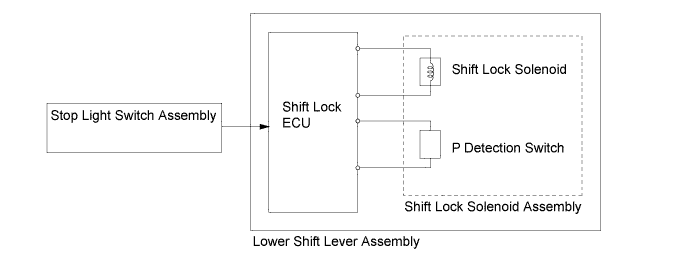
Shift Lock System
-
The shift lock system uses the shift lock ECU to control the shift lock function.
-
The shift lock function prevents the shift lever from being moved from P, unless the power switch is on (IG or READY) and the brake pedal is depressed.
-
A concealed shift lock release button allows for a manual override of the shift lock system if this is necessary.
-
-
-
OPERATION
-
Motive Force Transmission Path
-
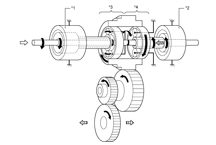
The motive force created by the engine and MG2 is transmitted by the counter drive gear of the compound gear unit, the counter driven gear, the final drive gear, and then the differential gear unit, in order to drive the front wheels.
Text in Illustration *1 Engine *2 Transmission Input Damper Assembly *3 MG1 *4 Compound Gear Unit *5 Sun Gear *6 MG2 *7 Oil Pump *8 Ring Gear *9 Carrier *10 Counter Drive Gear (Compound Gear) *11 Final Drive Gear *12 Counter Driven Gear *13 Final Driven Gear *14 Differential Gear Unit
-
-
Engine Motive Force and MG2 Motive Force Transmission Path
-
The engine motive force, which is input by the carrier, is transmitted to the ring gear. The motive force of MG2 is transmitted to the ring gear via the motor speed reduction planetary gear unit. The sum of these two motive forces is transmitted by the compound gear in order to drive the wheels.
Text in Illustration *1 MG1 *2 MG2 *3 Power Split Planetary Gear Unit *4 Motor Speed Reduction Planetary Gear Unit 
Rotation Direction 
From Engine 
From MG2 
To Wheels
-
-
MG2 Motive Force Transmission Path
-
The motive force of MG2 is transmitted via the sun gear and is output to the ring gear in order to drive the wheels. The carrier of the motor speed reduction planetary gear unit is fixed. As a result, the motor speed reduction planetary gear unit reduces the speed of MG2, increasing torque in accordance with a set gear ratio. The direction of rotation of MG2 changes according to whether the vehicle is travelling forward or in reverse.
Text in Illustration (Driving Forward:) *1 MG1 *2 MG2 *3 Power Split Planetary Gear Unit *4 Motor Speed Reduction Planetary Gear Unit Rotation Direction From MG2 To Wheel - - 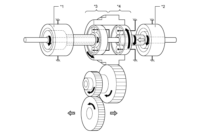
Text in Illustration (Driving in Reverse:) *1 MG1 *2 MG2 *3 Power Split Planetary Gear Unit *4 Motor Speed Reduction Planetary Gear Unit Rotation Direction From MG2 To Wheel - -
-
-
Engine Motive Force Transmission Path
-
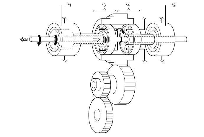
The engine motive force, which is input by the carrier, is transmitted to the sun gear. Thus, motive force is transmitted in order to operate MG1 as a generator.

Text in Illustration *1 MG1 *2 MG2 *3 Power Split Planetary Gear Unit *4 Motor Speed Reduction Planetary Gear Unit Rotation Direction From Engine To MG1 - -
-
-
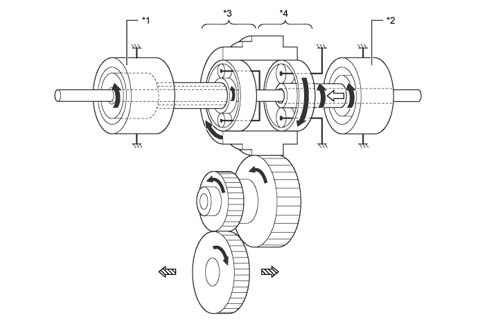
MG1 Motive Force Transmission Path
-
The motive force of MG1 is transmitted via the sun gear and is output to the carrier. Thus, motive force is transmitted in order to start the engine.
Text in Illustration *1 MG1 *2 MG2 *3 Power Split Planetary Gear Unit *4 Motor Speed Reduction Planetary Gear Unit Rotation Direction From MG1 To Engine - -
-
-