LUBRICATION SYSTEM DETAILS
-
CONSTRUCTION
-
Oil Pump
-
A compact cycloid rotor type oil pump directly driven by the crankshaft is used.
-
This oil pump uses an internal relief method which circulates relief oil to the suction passage in the oil pump. This aims to minimize oil level change in the oil pan, reduce friction, and reduce the air mixing rate in the oil.
-
-
Oil Strainer Sub-assembly
-
A low engine height is achieved due to the use of a light and compact oil strainer sub-assembly made of resin.
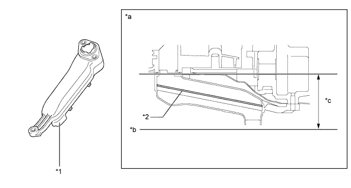
Text in Illustration *1 Oil Strainer Sub-assembly *2 Strainer *a Cross Section *b Bottom of Oil Pan *c Low profile due to use of resin - -
-
-
Oil Nozzle Sub-assembly
-
Oil nozzle sub-assemblies are provided on the left side of the cylinder block for cooling and lubricating the pistons.
-
These oil nozzle sub-assemblies contain a check valve to prevent oil from being fed when the oil pressure is low. This prevents the overall oil pressure in the engine from dropping.
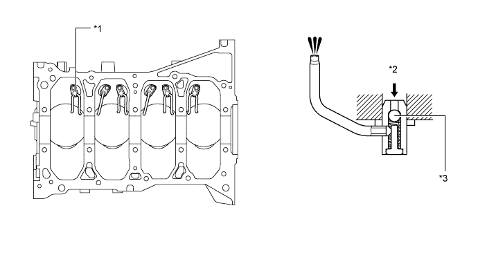
Text in Illustration *1 Oil Nozzle Sub-assembly *2 Oil *3 Check Valve - -
-
-
Oil Filter
-
An oil filter with a replaceable oil filter element is used. The oil filter element uses a high performance filter paper to improve filtration performance. It is also combustible for environmental protection.
-
An aluminum alloy filter cap sub-assembly is used to extend its life.
-
This oil filter has a structure which can allow the draining of the oil remaining in the oil filter. This prevents oil from spattering when replacing the oil filter element and allows the technician to work without touching hot oil.
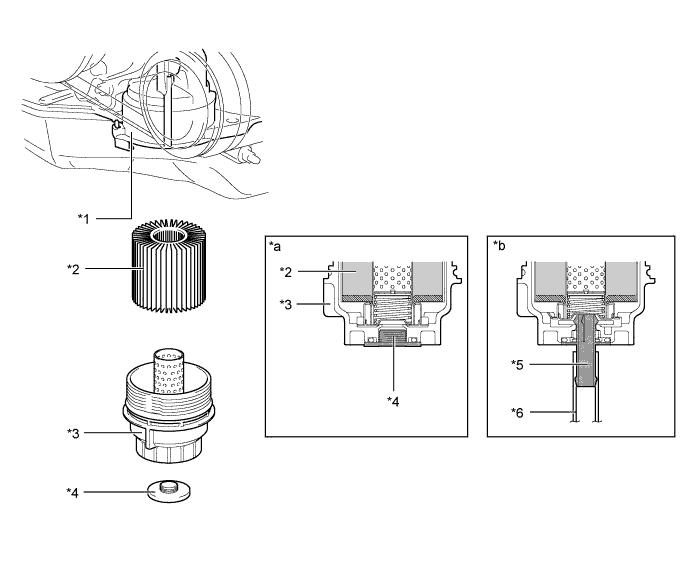
Text in Illustration *1 Crankcase *2 Element *3 Oil Filter Cap Assembly *4 Oil Filter Drain Plug *5 Drain Pipe *6 Hose (Inside Diameter: 15 mm (0.59 in.)) *a Cross Section *b When Draining Oil
-
-