EMISSION CONTROL SYSTEM DETAILS
-
FUNCTION OF MAIN COMPONENTS
-
The main components of the 2AR-FXE emission control system are as follows.
Component Function TWC Oxidizes CO and HC in the exhaust gas and deoxidizes NOx at the same time, to purify them into CO2, H2O and N2.
Oxygen Sensor This sensor detects the oxygen concentration in the exhaust emission by measuring the electromotive force which is generated in the sensor itself. Air Fuel Ratio Sensor As with the oxygen sensor, this sensor detects the oxygen concentration in the exhaust gas. However, it detects the oxygen concentration in the exhaust gas linearly. E.F.I. Vacuum Sensor Assembly Uses built-in semiconductors to detect the intake manifold pressure. EGR Valve Assembly Operates when receiving signals from the ECM, regulating the EGR volume. EGR Cooler Cools the exhaust gas temperature to improve the EGR efficiency. PCV Valve Opens and closes using vacuum generated in the intake manifold and controls the flow rate of the blowby gas. Charcoal Canister Assembly Contains activated charcoal to absorb the fuel vapor that is created in the fuel tank assembly. Canister Pump Module Vent Valve Opens and closes the fresh air line in accordance with signals from the ECM. Leak Detection Pump Applies vacuum to the evaporative emission system in accordance with signals from the ECM. Canister Pressure Sensor Detects the pressure in the evaporative emission system and sends the signals to the ECM. Canister Filter Prevents dust and debris in the fresh air from entering the system. Fresh Air Line Fresh air goes into the charcoal canister assembly and the cleaned drain air goes out into the atmosphere. Purge VSV Opens in accordance with the signals from the ECM when the system is purging, in order to send the fuel vapor that was absorbed by the charcoal canister assembly into the intake manifold. In system monitoring mode, this valve controls the introduction of vacuum into the fuel tank assembly. ECM -
Controls the volume of fuel injected, with corrections based primarily on the signal from the air fuel ratio sensor, and minor corrections based on the signal from the oxygen sensor. This control optimizes the air-fuel ratio.
-
Regulates the EGR volume in accordance with the various sensor signals.
-
Controls the canister pump module and the purge VSV in accordance with the signals from various sensors, in order to achieve a purge volume that suits the driving conditions. In addition, the ECM monitors the system for any leaks and stores a DTC if a malfunction is found.
-
-
-
OPERATING CONDITION
-
The following are the typical conditions necessary to enable an evaporative emission leak check:
Typical Enabling Conditions -
5 hours have elapsed after the engine has been turned off*.
-
Altitude: Below 2400 m (8000 ft.)
-
Battery Voltage: 10.5 V or more
-
Power Switch: Off
-
Engine Coolant Temperature: 4.4 to 35°C (40 to 95°F)
-
Intake Air Temperature: 4.4 to 35°C (40 to 95°F)
-
*: If engine coolant temperature does not drop below 35°C (95°F), this time is extended to 7 hours. Even after that, if the temperature is not less than 35°C (95°F), the time is extended to 9.5 hours.
Tech Tips
The canister pump module performs a fuel evaporative emission leak check. This check is done approximately 5 hours after the engine is turned off. Sound may be heard coming from underneath the luggage compartment for several minutes. This does not indicate a malfunction. Pinpoint pressure test procedure is adopted by pressurizing the fresh air line that runs from the canister pump module to the air filler neck. For details, refer to the Repair Manual.
-
-
-
SYSTEM CONTROL
-
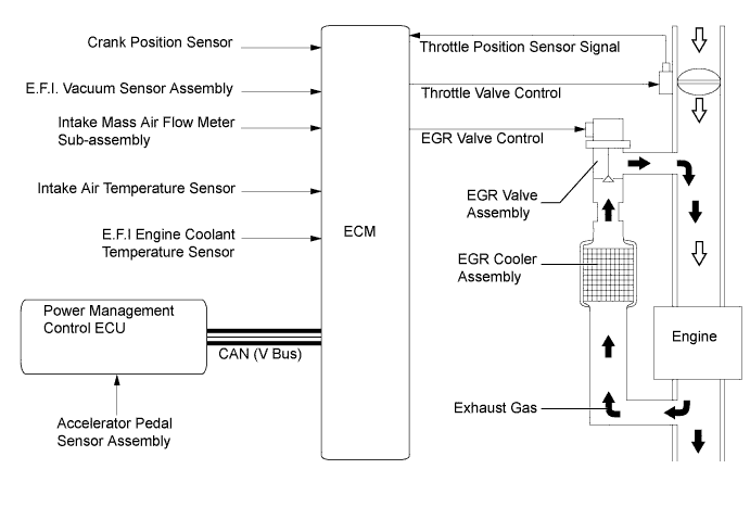
EGR Control
-
For the EGR system, a regulated amount of inert gas is allowed to flow into the intake passage, reducing the peak temperature in the engine combustion chamber.
-
By sensing the engine driving conditions and actual amount of the EGR valve opening, the ECM operates the EGR valve and throttle control motor, to regulate the amount of exhaust gas that is recirculated.
-
-
Blowby Gas Ventilation System
-
By introducing blowby gas that has a large amount of HC into the intake manifold for combustion, the system enhances the emission performance. The amount of airflow through the crankcase (blowby gas introduction volume) is controlled according to the engine operating conditions. This prevents the excessive consumption of engine oil, and is a factor in idle speed control.
-
An oil separator is provided in the blowby gas passage inside the cylinder block sub-assembly. This separates the engine oil from the blowby gas in order to reduce oil degradation and reduce the amount of engine oil consumed.
-
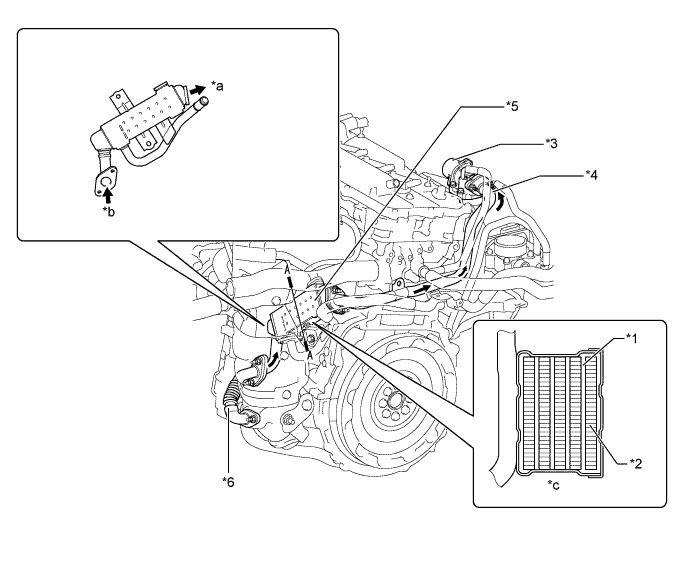
The Positive Crankcase Ventilation (PCV) valve passage returns the blowby gas into the area after the throttle valve in accordance with the intake manifold vacuum.
-
When engine load is low, the intake manifold vacuum draws gases from the crankcase via the PCV valve, oil separator and hose. Fresh air is supplied to the crankcase to replace the gases drawn in through the PCV valve. The passage from the area before the throttle to the cylinder head cover sub-assembly supplies this fresh air to the crankcase.
-
When engine load is high, some of the gases in the crankcase (including blowby gas) are supplied to the intake manifold from the crankcase via the PCV valve, oil separator and hose, and the remaining gases are transferred via the passage from the cylinder head cover sub-assembly to the area before the throttle.
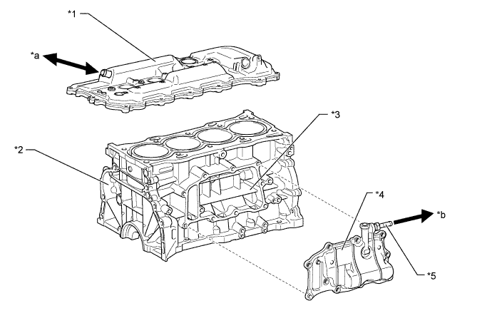
Text in Illustration *1 Cylinder Head Cover Sub-assembly *2 Cylinder Block Sub-assembly *3 Oil Separator *4 Ventilation Case Sub-assembly *5 PCV Valve - - *a To Air Cleaner Hose *b To Intake Manifold 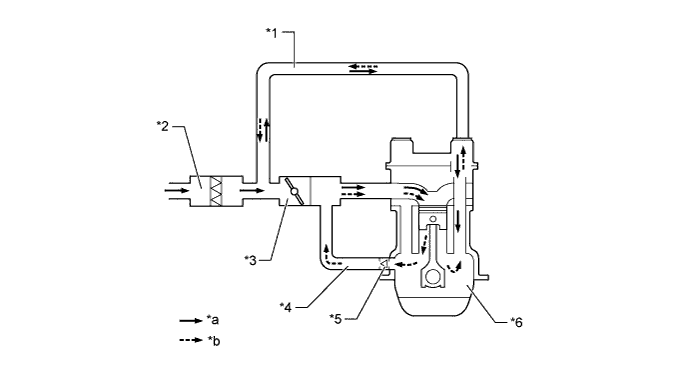
Text in Illustration *1 No. 2 Ventilation Hose *2 Air Cleaner Case *3 Throttle Body with Motor Assembly *4 No. 1 Ventilation Hose *5 PCV Valve *6 Crankcase *a Fresh Air *b Blowby Gas
-
-
Purge Flow Control
-
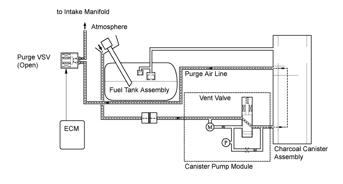
The canister stores the fuel vapors that have been created in the fuel tank assembly.
-
When the engine has reached a predetermined state (closed loop, engine coolant temp. above 40 °C (104 °F), etc.), stored fuel vapors are purged from the canister whenever the purge VSV is opened by the ECM.
-
The ECM will change the duty ratio cycle of the purge VSV, thus controlling purge flow volume. Purge flow volume is determined by intake manifold pressure and the duty ratio cycle of the purge VSV. Atmospheric pressure is allowed into the canister to ensure that purge flow is constantly maintained whenever purge vacuum is applied to the canister.
-
-
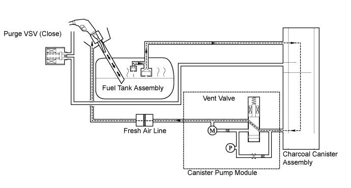
On-Board Refueling Vapor Recovery (ORVR)
-
When the internal pressure of the fuel tank assembly increases during refueling, fuel vapors are fed to the canister. The air that has had the fuel vapors removed from it will be discharged through the fresh air line.
-
The vent valve is used to open and close the fresh air line, and it is always open (even when the engine is stopped) except when the vehicle is in monitoring mode (the valve will be open as long as the vehicle is not in monitoring mode). If the vehicle is refueled in system monitoring mode, the ECM will recognize the refueling by way of the canister pressure sensor, which detects the sudden pressure increase in the fuel tank assembly, and the ECM will open the vent valve.
-
-
EVAP Leak Check
-
The EVAP leak check operates in accordance with the following timing chart:
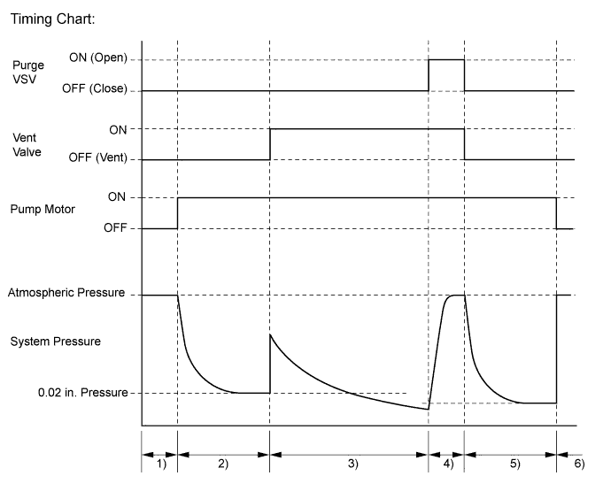
Order Operation Description Time 1) Atmospheric Pressure Measurement The ECM turns the vent valve off (vent) and measures EVAP system pressure to determine the atmospheric pressure. 60 sec. 2) 0.02 in. Leak Pressure Measurement The leak detection pump creates negative pressure (vacuum) through a 0.02 in. orifice and the pressure is measured. The ECM determines this as the 0.02 in. leak pressure.
The purpose of this measurement is to confirm vacuum pump operation, and to provide a baseline measurement value that will be used for comparison in subsequent leak test steps.
360 sec. 3) EVAP Leak Check The leak detection pump creates negative pressure (vacuum) in the EVAP system and the EVAP system pressure is measured.
If the stabilized pressure is larger than the 0.02 in. leak pressure, the ECM determines that the EVAP system has a leak.
If the EVAP pressure does not stabilize within 15 minutes, the ECM cancels EVAP monitor.
Within 15 min. 4) Purge VSV Monitor The ECM opens the purge VSV and measures the EVAP pressure increase. If the increase is large, the ECM interprets this as normal. 10 sec. 5) Repeat 0.02 in. Leak Pressure Measurement The leak detection pump creates negative pressure (vacuum) through the 0.02 in. orifice and the pressure is measured. The ECM determines this as the 0.02 in. leak pressure. 60 sec. 6) Final Check The ECM measures the atmospheric pressure and records the monitor result. -
-
-
-
CONSTRUCTION
-
Three-Way Catalytic converter (TWC)
-
TWCs are provided in the exhaust manifold sub-assembly and also in the front exhaust pipe assembly.
-
An exhaust manifold with an integrated TWC is used for warm-up of the TWC in the front exhaust pipe assembly.
-
An ultra thin-wall, high-cell density, ceramic type TWC is used for the exhaust manifold sub-assembly and a thin-wall, ceramic type TWC is used for the front exhaust pipe assembly.
-
The ultra thin-wall TWC enables improved exhaust emissions by optimizing the cell density and the wall thickness.
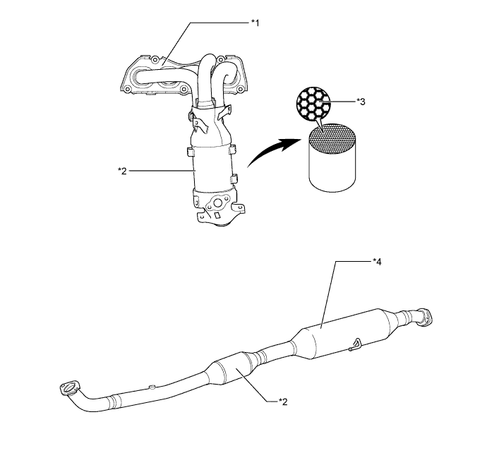
Text in Illustration *1 Exhaust Manifold Sub-assembly *2 TWC *3 Ultra Thin-wall *4 Front Exhaust Pipe Assembly
-
-
EGR Valve and EGR Cooler
-
A step motor type EGR valve is used to precisely control the EGR gas flow amount.
-
The EGR cooler cools the exhaust gas to improve the EGR efficiency.
Text in Illustration *1 Water Passage *2 EGR Gas Passage *3 EGR Valve Assembly *4 No. 1 EGR Pipe *5 EGR Cooler Assembly *6 No. 2 EGR Pipe *a To EGR Valve Assembly *b From Exhaust Manifold *c A-A Cross Section - - 
EGR Gas - -
-
-
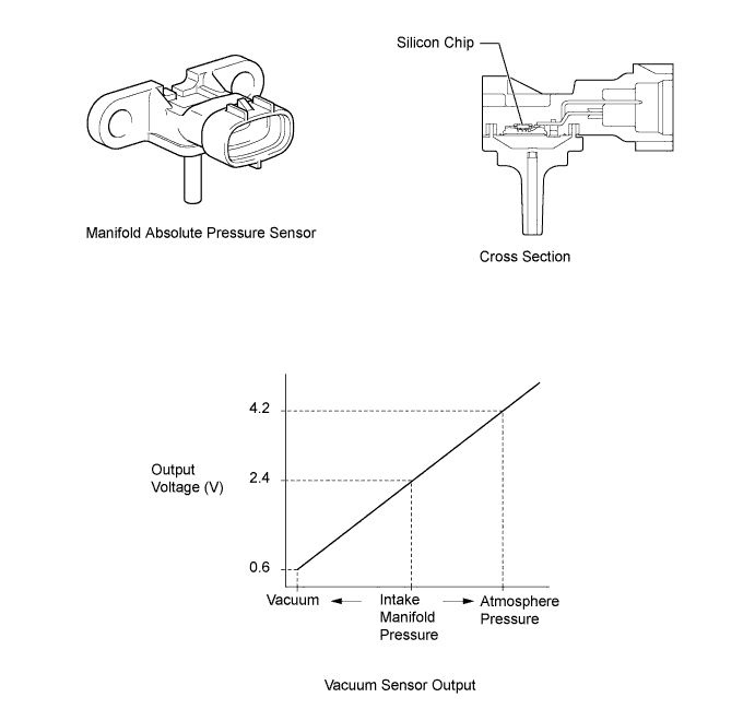
E.F.I. Vacuum Sensor Assembly
-
An E.F.I. vacuum sensor assembly is used to measure the intake manifold pressure for EGR control.
-
The E.F.I. vacuum sensor assembly consists of a silicon chip which utilizes the characteristics of a silicon chip that changes its electrical resistance when pressure is applied to it. The sensor converts the pressure into an electrical signal, and sends it to the ECM in an amplified form.
-
-
Fuel Tank Cap Assembly
-
ID mark B is printed on the fuel tank cap assembly.
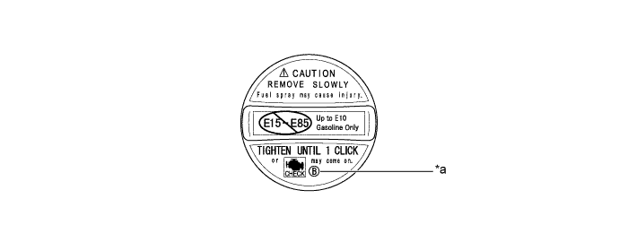
Text in Illustration *a ID Mark - - CAUTION:
Make sure to use a fuel tank cap assembly that has the same ID mark, or a malfunction may occur in the fuel system.
-
-
-
OPERATION
-
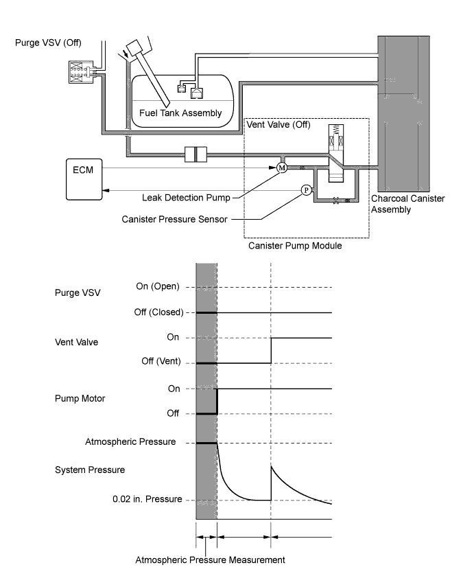
Atmospheric Pressure Measurement
-
When the power switch is turned off, the purge VSV and the vent valve are turned off. Therefore, atmospheric pressure is introduced into the canister.
-
The ECM measures the atmospheric pressure based on the signals provided by the canister pressure sensor.
-
If the measurement value is out of standards, the ECM actuates the leak detection pump in order to monitor the changes in the pressure.
-
-
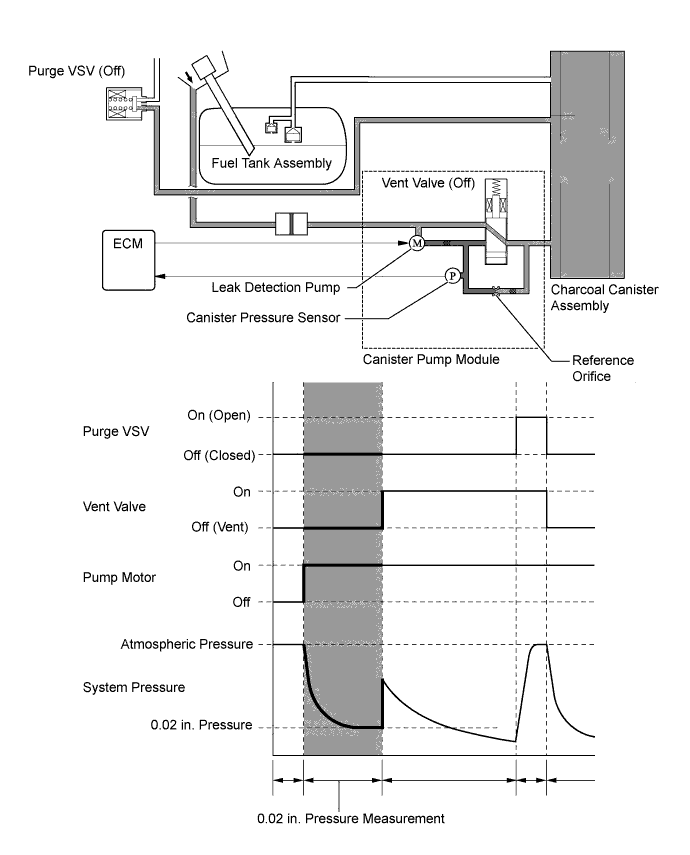
0.02 in. Leak Pressure Measurement
-
The vent valve remains off, and the ECM introduces atmospheric pressure into the canister and actuates the leak detection pump in order to create a negative pressure.
-
At this time, the pressure will not decrease beyond a 0.02 in. pressure due to the atmospheric pressure that enters through a 0.02 in. diameter reference orifice.
-
The ECM compares the logic value and this pressure, and stores it as a 0.02 in. leak pressure in its memory.
-
If the measurement value is below the standard, the ECM will determine that the reference orifice is clogged and store Diagnostic Trouble Code (DTC) P043E in its memory.
-
If the measurement value is above the standard, the ECM will determine that a high flow rate pressure is passing through the reference orifice and store Diagnostic Trouble Code (DTC) P043F, P2401 and P2402 in its memory.
-
-
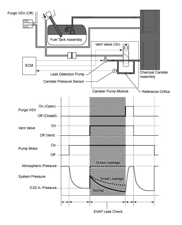
EVAP Leak Check
-
While actuating the leak detection pump, the ECM turns the vent valve on in order to introduce a vacuum into the canister.
-
When the pressure in the system stabilizes, the ECM compares this pressure and the 0.02 in. pressure in order to check for a leakage.
-
If the detection value is below the 0.02 in. pressure, the ECM determines that there is no leakage.
-
If the detection value is above the 0.02 in. pressure and near atmospheric pressure, the ECM determines that there is a gross leakage (large hole).
-
If the detection value is above the 0.02 in. pressure, the ECM determines that there is a small leakage.
-
-
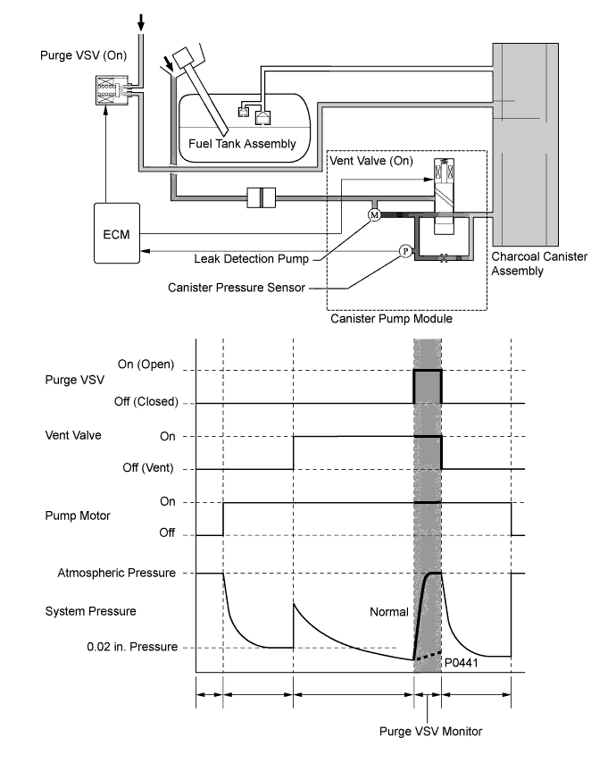
Purge VSV Monitor
-
After completing an EVAP leak check, the ECM turns the purge VSV on (open) with the leak detection pump actuated, and introduces the atmospheric pressure from the intake manifold to the canister.
-
If the pressure change at this time is within the normal range, the ECM determines the condition to be normal.
-
If the pressure is out of the normal range, the ECM will stop the purge VSV monitor and store DTC P0441 in its memory.
-
-
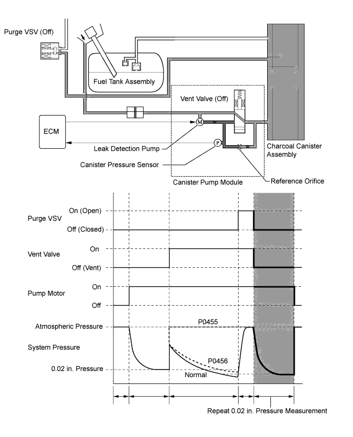
Repeat 0.02 in. Leak Pressure Measurement
-
While the ECM operates the leak detection pump, the purge VSV and vent valve turn off and a repeat 0.02 in. leak pressure measurement is performed.
-
The ECM compares the measured pressure with the pressure during EVAP leak check.
-
If the pressure during the EVAP leak check is below the measured value, the ECM determines that there is no leakage.
-
If the pressure during the EVAP leak check is above the 0.02 in. pressure and near atmospheric pressure, the ECM determines that there is a gross leakage (large hole) and stores DTC P0455 in its memory.
-
If the pressure during the EVAP leak check is above the 0.02 in. pressure, the ECM determines that there is a small leakage and stores DTC P0456 in its memory.
-
-