MULTI-TERRAIN MONITOR SYSTEM DETAILS
-
FUNCTION OF MAIN COMPONENTS
Component Function Multi Display Assembly*1 Receives image signals transmitted from the parking assist ECU and displays them. Accessory Meter Assembly*2 Receives image signals transmitted from the parking assist ECU and displays them. Driving Support Switch Control ECU -
Transmits signals from the multi-information switch to the parking assist ECU.
-
Transmits signals from the parking assist ECU to the accessory meter assembly.*2
Television Camera Assemblies Outputs the images received by television camera assemblies installed on the front grille, outer rear view mirror and back door*3 or back door spare tire carrier*4 to the parking assist ECU. Parking Assist ECU -
Turns the multi-terrain monitor system on/off in accordance with the signals input from the ECUs and switches.
-
Outputs visual signals from the television camera assemblies to the multi display assembly*1 or the accessory meter assembly*2.
Combination Meter Assembly Illuminates the multi-terrain indicator light while the multi-terrain select is on. Multi-information Switch (Steering Pad Switch Assembly) -
The multi-terrain select can be operated by operating this switch.
-
The multi-terrain monitor screen can be switched by operating this switch while multi-terrain select is operating.
Wide View Front and Side Monitor Switch Switches between the screen of the multi-terrain monitor and wide view front and side monitor system. ECM Outputs shift position signals to the parking assist ECU. Park/Neutral Position Switch Assembly*5 Transmits shift position signals to the ECM or TCM*6. Skid Control ECU Transmits speed sensor signal to the parking assist ECU. TCM*6 Transmits shift position signals received from the park/neutral start switch assembly*7 to the ECM. -
*1: Models with navigation system
-
*2: Models without navigation system
-
*3: Models without back door spare tire carrier
-
*4: Models with back door spare tire carrier
-
*5: Models with automatic transmission
-
*6: Models with 1KD-FTV engine
-
-
OPERATING CONDITION
-
The multi-terrain monitor system will display under the following conditions:
-
Engine switch is on (IG) or on (ACC).
-
Multi-terrain select is on.
-
The outer rear view monitor is opened.
-
Vehicle speed is 10 km/h (6 mph) or less.
-
Multi-terrain monitor system is on.
-
-
-
FUNCTION
-
Area Displayed on Screen
-
By operating the multi-information switch, the "cam. position" display on the multi-information display of the combination meter assembly can be used to select the television camera assembly displayed on the multi display assembly*1 or accessory meter assembly*2.
-
*1: Models with navigation system
-
*2: Models without navigation system
Camera Position Shift Position N or Forward R Camera Position Front 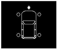
- Side Front 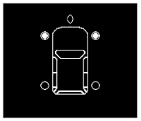
Side Rear 
Rear - 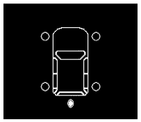
-
-
The front, rear and side television camera assemblies can capture images within the area shown below. However, the display area may differ, depending on the conditions of the vehicle or the road.
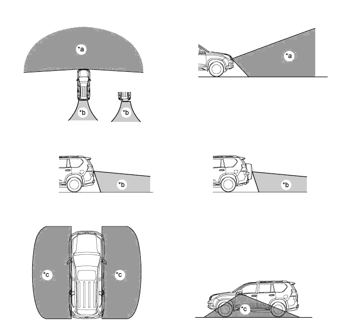
Text in Illustration *a Front Television Camera Assembly Capture Range *b Rear Television Camera Assembly Capture Range *c Side Television Camera Assembly Capture Range - -
-
-
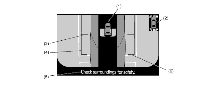
Front View Mode
-
The front view mode shows the conditions in front of the vehicle.
-
In the front view mode, the screen displays as shown in the illustration below:
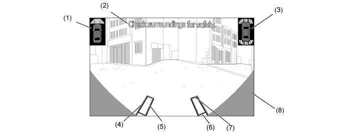
Item Description of Display (1) Vehicle Icon Shows the display range of the front view mode. (2) Warning Message Display Area Displays a warning message. (3) TOYOTA Parking Assist-sensor System Icon Shows the obstacle detection position of the TOYOTA parking assist-sensor system. (4) Trajectory Line (Outside) Indicates the outer path of the wheel. (5) Trajectory Line (Inside) Indicates the inner path of the wheel. (6) Distance Guide Line (Red) Shows a point approx. 0.5 m (19.7 in.) ahead of the front edge of the vehicle. (7) Distance Guide Line (Yellow) Shows a point approx. 1.0 m (39.4 in.) ahead of the front edge of the vehicle. (8) Parts Which Show The Vehicle Parts which show same of the radiator grill and bumper.
-
-
Side Front Simultaneous View Mode
-
The side front simultaneous view mode shows the conditions in side of the vehicle.
-
In the side front simultaneous view mode, the screen displays as shown in the illustration.
Item Description of Display (1) Vehicle Icon Shows the screen display range of the side front simultaneous view mode. (2) Vehicle Front Edge Shows the front edge of the vehicle using a guide line. (3) TOYOTA Parking Assist-sensor System Icon Shows the obstacle detection position of the TOYOTA parking assist-sensor system. (4) Front Wheel Road Contact Line Shows the position of the front wheels. (5) Vehicle Parallel Line Shows the vehicle width including the outer rear view mirrors by displaying lines that run parallel with the body line. (6) Warning Message Display Area Displays a warning message.
-
-
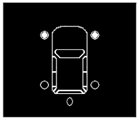
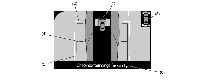
Side Rear Simultaneous View Mode
-
The side rear simultaneous view mode shows the conditions in side of the vehicle.
-
In the side rear simultaneous view mode, the screen displays as shown in the illustration below:
Item Description of Display (1) Vehicle Icon Shows the screen display range of the side rear simultaneous view mode. (2) TOYOTA Parking Assist-sensor System Icon Shows the obstacle detection position of the TOYOTA parking assist-sensor system. (3) Rear Wheel Road Contact Line Shows the position of the rear wheels. (4) Vehicle Parallel Line Shows the vehicle width including the outer rear view mirrors by displaying lines that run parallel with the body line. (5) Warning Message Display Area Displays a warning message. (6) Vehicle Rear Edge Shows the rear edge of the vehicle using a guide line.
-
-
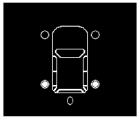
Rear View Mode
-
The rear view mode shows the conditions in rear of the vehicle.
-
In the rear view mode, the screen displays as shown in the illustration below:
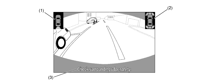
Item Description of Display (1) Vehicle Icon Shows the display range of the rear view mode. (2) TOYOTA Parking Assist-sensor System Icon Shows the obstacle detection position of the TOYOTA parking assist-sensor system. (3) Warning Message Display Area Displays a warning message.
-
-
Warning Message
-
A warning message appears at the bottom, side or center of the screen under the conditions listed below. The warning message appears in the language that has been selected by the language selector of the navigation screen display.
Messages Appearing at Bottom or Side of Screen Warning Message Outline Check surroundings for safety This message always appears during system operation. Guidance Unavailable This message is displayed when an error in the steering angle sensor occurs.
-
-
-
CONSTRUCTION
-
Television Camera Assembly
-
The television camera assembly consists of a wide angle lens and a Charge Coupled Device (CCD).
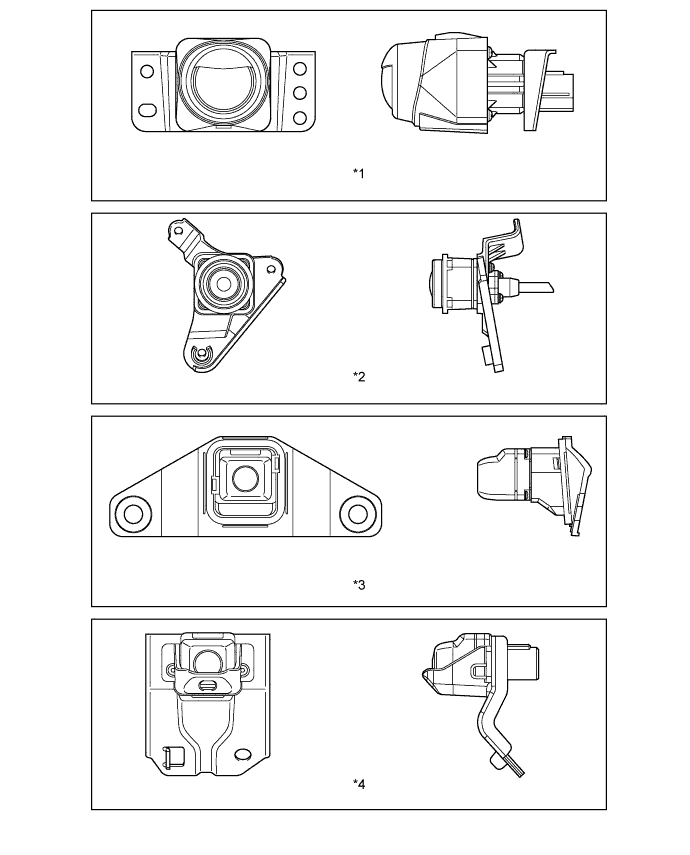
Text in Illustration *1 For Front Television Camera Assembly *2 For Side Television Camera Assembly *3 For Rear Television Camera Assembly (Models without Spare Tire Back Door Carrier) *4 For Rear Television Camera Assembly (Models with Spare Tire Back Door Carrier)
-
-
Accessory Meter Assembly (Models without Navigation System)
-
By operating the DISP switch and the up/down switch, contrast and brightness will be displayed on the screen and can be adjusted.
-
Contrast can be adjusted in 11 stages.
-
Brightness can be adjusted in 11 stages.

-
-
-
-
OPERATION
-
Display Transition
-
The multi display assembly of the multi-terrain monitor system makes the following transitions:
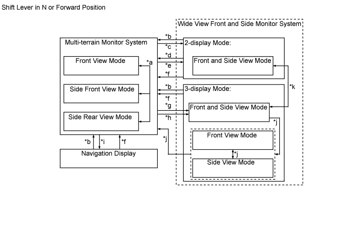
Item Transition Condition *a The multi-information switch is operated. *b The vehicle speed becomes approx. 10 km/h (6 mph) or less while the multi-terrain select is operating. *c Multi-terrain monitor system operating conditions become unfulfilled or the multi-terrain select is switched off, and the wide view front and side monitor system was displayed in 2-display mode prior to operation of the multi-terrain select. *d The wide view front and side monitor switch is pressed a second time after being pressed while multi-terrain select is operating to switch to the wide view front and side monitor system. *e The wide view front and side monitor switch is pressed while multi-terrain select is operating, and the wide view front and side monitor system was displayed in 2-display mode prior to the multi-terrain select operation. *f The multi-information switch is operated and multi-terrain select is operated when the vehicle speed is at 10 km/h (6 mph) or below. *g Multi-terrain monitor system operating conditions become unfulfilled or the multi-terrain select is switched off, and the wide view front and side monitor system was displayed in 3-display mode prior to multi-terrain select operation. *h The wide view front and side monitor switch is pressed while multi-terrain select is operating, and the wide view front and side monitor system was displayed in 3-display mode prior to multi-terrain select operation. *i Multi-terrain monitor system operating conditions become unfulfilled or the multi-terrain select is switched off, and the navigation display was shown prior to operation of the multi-terrain select. *j The wide view front and side monitor switch is pressed. *k The display mode switch inside the display is pressed. 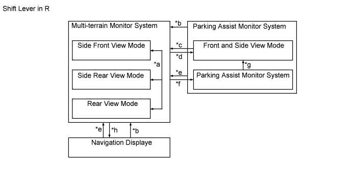
Item Transition Condition *a The multi-information switch is operated. *b The multi-information switch is operated and multi-terrain select is operated when the vehicle speed is at 10 km/h (6 mph) or below. *c The wide view front and side monitor switch is pressed a second time after being pressed while multi-terrain select is operating to switch to the parking assist monitor system. *d The wide view front and side monitor switch is pressed while multi-terrain select is operating, and the parking assist monitor system was displayed prior to multi-terrain select operation. *e The vehicle speed becomes approx. 10 km/h (6 mph) or less while the multi-terrain select is operating. *f Multi-terrain monitor system operating conditions become unfulfilled or the multi-terrain select is switched off, and the parking assist monitor system was displayed prior to operation of the multi-terrain select. *g The wide view front and side monitor switch is pressed. *h Multi-terrain monitor system operating conditions become unfulfilled or the multi-terrain select is switched off, and the navigation display was shown prior to operation of the multi-terrain select. -
The accessory meter assembly of the multi-terrain monitor system makes the following transitions:

Item Transition Condition *a The multi-information switch is operated. *b The multi-information switch is operated and multi-terrain select is operated when the vehicle speed is at 10 km/h (6 mph) or below. *c Multi-terrain monitor system operating conditions become unfulfilled or the multi-terrain select is switched off, and the wide view front and side monitor system was displayed prior to operation of the multi-terrain select. *d The wide view front and side monitor switch is pressed while multi-terrain select is operating, and the wide view front and side monitor system was displayed prior to multi-terrain select operation. *e The wide view front and side monitor switch is pressed. *f The vehicle speed becomes approx. 10 km/h (6 mph) or less while the multi-terrain select is operating. *g Multi-terrain monitor system operating conditions become unfulfilled or the multi-terrain select is switched off, and the driver monitor display was shown prior to operation of the multi-terrain select. 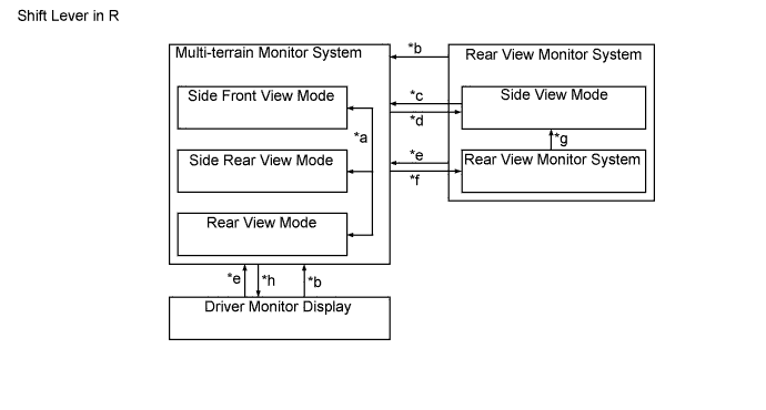
Item Transition Condition *a The multi-information switch is operated. *b The multi-information switch is operated and multi-terrain select is operated when the vehicle speed is at 10 km/h (6 mph) or below. *c While multi-terrain select is operating, the wide view front and side monitor switch is pressed a second time after being pressed to switch to the rear view monitor system. *d The wide view front and side monitor switch is pressed while multi-terrain select is operating, and the rear view monitor system was displayed prior to multi-terrain select operation. *e The vehicle speed becomes approx. 10 km/h (6 mph) or less while the multi-terrain select is operating. *f Multi-terrain monitor system operating conditions become unfulfilled or the multi-terrain select is switched off, and the rear view monitor system was displayed prior to operation of the multi-terrain select. *g The wide view front and side monitor switch is pressed. *h Multi-terrain monitor system operating conditions become unfulfilled or the multi-terrain select is switched off, and the driver monitor display was shown prior to operation of the multi-terrain select.
-
-
Checking Traveling Direction and Avoiding Obstacles
-
In order to avoid obstacles while traveling forward, the driver should steer in such a way that the wheel path does not overlap with any obstacles. By doing so, obstacles can be avoided and passed.

Tech Tips
-
As it is difficult to understand the height differences of obstacles using the images received from the cameras, care should be taken of large differences in height.
-
As it is difficult to perceive distances using the images of the wide view front camera assembly, distances to items displayed should be confirmed directly.
-
-
-
-
FAIL-SAFE
-
The table below indicates the conditions of detecting malfunctions in the components of this system.
Malfunction Parts Detection Item Function Steering Angle Sensor -
Transmission of sensor malfunction signal
-
Open circuit in sensor signal
-
Communication malfunction between the steering angle sensor and parking assist ECU
Displays "Guidance Unavailable" Television Camera Assemblies Transmission of television camera malfunction signal Stops signal reception and displays a dark screen Parking Assist ECU Malfunction of parking assist ECU Stops system operation -
-
-
DIAGNOSIS
-
The multi-terrain monitor system is equipped with a diagnosis function which can display the service menus. The method for entering the service menu screen is the same as the method used for the multi display. For details, refer to the corresponding Repair Manual for this model.
-