WIDE VIEW FRONT AND SIDE MONITOR SYSTEM DETAILS
-
FUNCTION OF MAIN COMPONENTS
Component Function Multi Display*1 Displays the image transmitted by the parking assist ECU on the screen. Accessory Meter Assembly*2 Displays the image transmitted by the parking assist ECU on the screen. Wide View Front and Side Monitor Switch Enables the driver to operate the wide view front and side monitor system from the steering pad switches. Parking Assist ECU -
Turns the wide view front and side monitor system on/off in accordance with the signals input from the ECU and switches.
-
Outputs visual signals from the front television camera and the side television camera to the multi display.
Television Camera Assemblies Outputs the images received by television camera assemblies installed on the front grille and passenger-side outer rear view mirror to the parking assist ECU. Skid Control ECU Outputs vehicle speed signals to the parking assist ECU. Steering Angle Sensor Assembly Detects the angle of the steering wheel, and transmits the signal to the parking assist ECU. ECM Outputs shift position signals to the parking assist ECU. Park/Neutral Position Switch Assembly*3 Transmits shift position signals to the ECM or TCM*5. Back-up Light Switch*4 Transmits shift position signals to the parking assist ECU. TCM*5 Transmits shift position signals to the ECM. -
*1: Models with navigation system
-
*2: Models without navigation system
-
*3: Models with automatic transmission
-
*4: Models with manual transmission
-
*5: Models with 1KD-FTV engine
-
-
OPERATING CONDITION
-
Manual Display Mode (Models with Navigation System)
-
The wide view front and side monitor system will display in manual under the following conditions:
-
Engine switch is on (IG) or on (ACC)
-
Vehicle speed is 12 km/h (7.5 mph) or less
-
Round monitor main switch is on
-
-
-
Manual Display Mode (Models without Navigation System)
-
The wide view front and side monitor system will display in manual under the following conditions:
-
Engine switch is on (IG) or on (ACC)
-
Vehicle speed is 10 km/h (6 mph) or less
-
Round monitor main switch is on
-
-
-
Auto Display Mode (Models with Navigation System)
-
The wide view front and side monitor system will display in automatic under the following conditions:
-
Engine switch is on (IG) or on (ACC)
-
The AUTO button in the screen display of the wide view front and side monitor system is on
-
Vehicle speed is 10 km/h (6 mph) or less
Tech Tips
After images have been displayed in manual display mode (on models without navigation system) and auto display mode, display will continue until the vehicle speed reaches 12 km/h (7.5 mph) or more.
-
-
-
-
FUNCTION
-
Area Displayed on Screen
-
The front and side television camera assemblies can capture images within the area shown below. However, the display area may differ, depending on the conditions of the vehicle or the road.
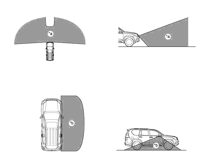
Text in Illustration *a Front Television Camera Assembly Capture Area *b Side Television Camera Assembly Capture Area
-
-
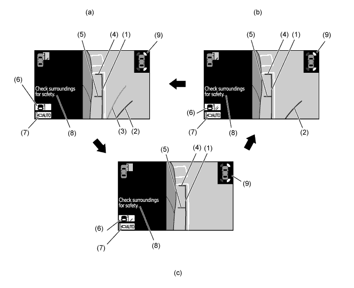
Front and Side View Mode (Models with Navigation System)
-
In the front and side view mode, the screen will simultaneously display the front view and the side view. When the wide view front and side monitor system is started, it will display in the front and side view mode.
-
In the front and side view mode, the driver can operate both the AUTO mode switch and the display mode switch.
-
In the front and side view mode, the screen displays as shown in the illustration below:
Item Description of Display (1) Vehicle Width Line (Green) Displays a parallel line approximately 0.35 m (13.8 in.) from the side of the vehicle body. (2) Estimated Minimum Turning Path Line (Green) Displays the approximate path of the vehicle when the steering wheel is turned all the way to the front passenger's side. (3) Estimated Course Line (Yellow) Displays the approximate path of the vehicle depending on the steering maneuver. (4) Vehicle Front Edge Line Displays a line approximately 0.1 m (3.9 in.) from the front end of the vehicle. (5) Front Wheel Contact Point Displays the position of the front wheel. (6) Rear Wheel Contact Point Displays the position of the rear wheel. (7) AUTO Mode Switch Turns the AUTO mode on and off. (8) Display Mode Switch Switches the display mode. (9) Warning Message Display Area Displays a warning message. (10) Parts Which Show The Vehicle Parts which show some of the radiator grill and bumper.
-
-
Front View Mode
-
The front view mode, which can be displayed in the three-display mode, shows the conditions ahead of the vehicle. Also, the AUTO mode switch can be operated in this mode.*1
-
The front view mode shows the conditions ahead of the vehicle.*2
-
*1: Models with navigation system
-
*2: Models without navigation system
Item Description of Display (1) AUTO Mode Switch* Turns the AUTO mode on and off. (2) Warning Message Display Area Displays a warning message. -
*: Models with navigation system
-
-
-
Side View Mode (Models with Navigation System)
-
The side view mode, which can be displayed in the three-display mode, shows the conditions on the front passenger side of the vehicle. The side view mode displays a zoom-in view of the front portion of the area that can be captured, thus enabling the driver to check the images easily. Also, the AUTO mode switch can be operated in this mode.
-
In the side view mode, images can be displayed even when the outer rear view mirror is retracted.
-
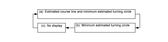
In the side view mode, the display mode of a predicted path line can be changed by pressing the predicted path line display mode select switch.
-
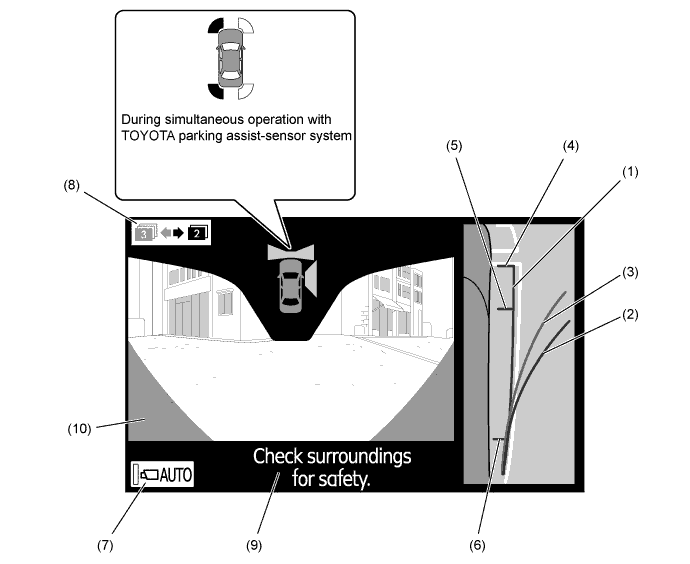
In the side view mode, the screen displays as shown in the illustration below:
Item Description of Display (1) Vehicle Width Parallel Line (Green) Displays a parallel line approximately 0.35 m (13.8 in.) from the side of the vehicle body. (2) Minimum Estimated Turning Circle (Green) Displays the approximate path of the vehicle when the steering wheel is turned all the way to the front passenger's side. (3) Estimated Course Line (Yellow) Displays the approximate path of the vehicle depending on the steering maneuver. (4) Vehicle Front Edge Line Displays a line approximately 0.1 m (3.9 in.) from the front end of the vehicle. (5) Front Wheel Contact Point Displays the position of the front wheel. (6) Display Mode Select Switch Changes the display mode of a predicted path line. Pressing this switch once changes to the next display mode. (7) AUTO Mode Switch* Turns the AUTO mode on and off. (8) Warning Message Display Area Displays a warning message. (9) TOYOTA Parking Assist-sensor System Indication Displays during simultaneous operation with the TOYOTA parking assist-sensor system. -
*: Models with navigation system
-
-
-
Side View Mode (Models without Navigation System)
-
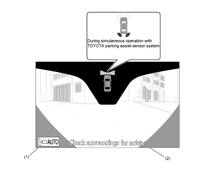
The side view mode shows the conditions at the side of the vehicle.
-
In the side view mode, the screen displays as shown in the illustration below:
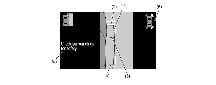
Item Description of Display (1) Vehicle Width Line (Green) Displays a parallel line approximately 0.35 m (13.8 in.) from the side of the vehicle body. (2) Vehicle Front Edge Line Displays a line approximately 0.1 m (3.9 in.) from the front end of the vehicle. (3) Front Wheel Contact Point Displays the position of the front wheel. (4) Rear Wheel Contact Point Displays the position of the rear wheel. (5) Warning Message Display Area Displays a warning message. (6) TOYOTA Parking Assist-sensor System Indication Displays during simultaneous operation with the TOYOTA parking assist-sensor system.
-
-
Warning Message
-
A warning message appears at the bottom, side or center of the screen under the conditions listed below. The warning message appears in the same language that has been selected by the language selector of the navigation screen display*1 or the combination meter*2.
-
*1: Models with navigation system
-
*2: Models without navigation system
Messages Appearing at Bottom or Side of Screen Warning Message Outline Check surroundings for safety This message always appears during system operation. System Initializing This message appears when the system is restarted if the parking assist computer detects that a battery terminal has been disconnected and subsequently reconnected. Guidance unavailable This message is displayed when an error occurs in the steering angle sensor. Messages Appearing at Center of Screen Warning Message Outline System not ready This message appears if the system is not initialized. -
-
-
-
CONSTRUCTION
-
Television Camera Assembly
-
The television camera assembly consists of a wide angle lens and a Charge Coupled Device (CCD).
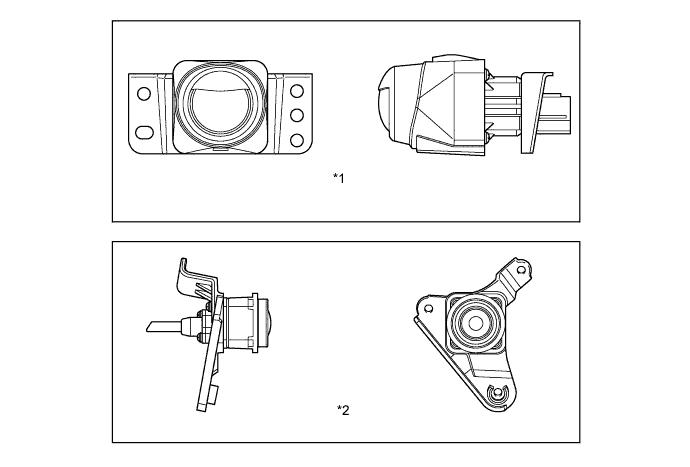
Text in Illustration *1 Front Television Camera Assembly *2 Side Television Camera Assembly
-
-
Accessory Meter Assembly (Models without Navigation System)
-
By operating the DISP switch and the up/down switch, contrast and brightness will be displayed on the screen and can be adjusted.
-
Contrast can be adjusted in 11 stages.
-
Brightness can be adjusted in 11 stages.

-
-
-
-
OPERATION
-
Display Transition
-
The display of the wide view front and side monitor system for models with navigation system makes the following transitions:
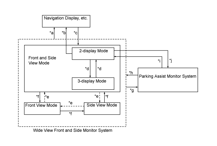
Item Transition Condition *a -
The vehicle speed has reached approximately 12 km/h (7.2 mph) or more.
-
A switch is pressed to request the display of another screen (for example, the INFO switch is pressed on the center cluster).
*b The wide view front and side monitor switch is pressed. *c -
The wide view front and side monitor switch is pressed when the vehicle speed is approximately 10 km/h (6.0 mph) or less.
-
The wide view front and side monitor system is on, the AUTO mode is on, and the following conditions are applicable:
-
The vehicle speed has reached approximately 10 km/h (6.0 mph) or less.
-
The switch-operated screen display has ended.
-
When the wide view front and side monitor system is started, or resumed automatically from another display, the screen will invariably display in the front and side view mode.
*d The display mode switch is pressed. *e The wide view front and side monitor switch is pressed under the following conditions:
-
The 3-display mode is selected.
-
The wide view front and side monitor system ended in the front view mode in the previous operation.
(The screen will not change to another display such as the navigation display. The screen will change between the front and side view mode, side view mode, and front view mode.)
*f The wide view front and side monitor switch is pressed under the following conditions:
-
The 3-display mode is selected.
-
The wide view front and side monitor system ended in the side view mode in the previous operation.
(The screen will not change to another display such as the navigation display. The screen will change between the front and side view mode, side view mode, and front view mode.)
*g The shift lever is moved to R. *h The shift lever is moved from R to N, D, or S when the AUTO mode is on. *i The wide view front and side monitor switch is pressed. (The transition conditions "*b" and "*d" are not available.) *j After the transition condition "*i" is satisfied, the wide view front and side monitor switch is pressed again. -
-
The display of the wide view front and side monitor system for models without navigation system makes the following transitions:
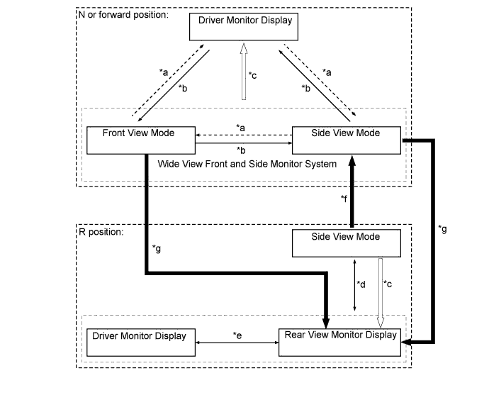
Item Transition Condition *a The wide view front and side monitor switch has been pressed when the wide view front and side monitor has been previously displayed and the last display was side view mode. *b The wide view front and side monitor switch has been pressed when the wide view front and side monitor has been previously displayed and the last display was front view mode. *c The vehicle speed is 12 km/h (7.2 mph) or more. *d The wide view front and side monitor switch is pressed. *e The DISP switch is pressed. *f The shift lever is moved from R to N or the forward position. *g The shift lever is moved from N or the forward position to R.
-
-
Avoiding Hitting Object during Turn
-
To avoid hitting an object during a turn, the driver should operate the steering wheel so as to prevent the predicted path line and the predicted minimum turning path line from overlapping with an object. By doing so, the driver can pass by the object without hitting it.
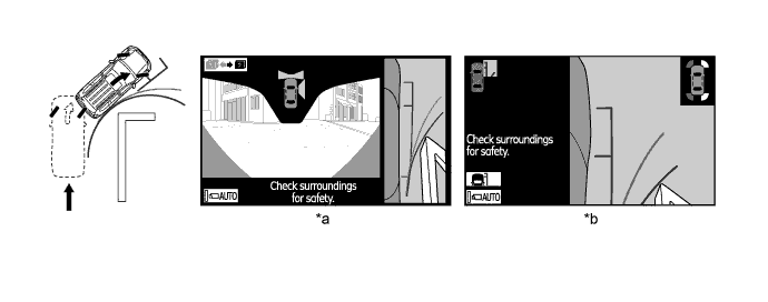
Text in Illustration *a Front and Side View Mode *b Side View Mode
-
-
Pulling Over to Side
-
To pull over to the side, the driver should operate the steering wheel so as to prevent the vehicle width parallel line from overlapping with white lines or curbs on the road. By doing so, the driver can pull over to the side smoothly.
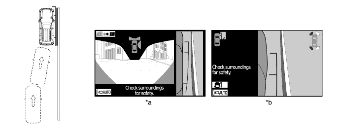
Text in Illustration *a Front and Side View Mode *b Side View Mode Tech Tips
If a battery terminal is disconnected, the assist function will not operate properly. This is because the present neutral steering point that is detected by the steering angle sensor does not match the neutral steering point that is stored in the memory of the parking assist ECU. Therefore, if the parking assist ECU detects that a battery terminal has been disconnected and the system is operated again after reconnecting the battery terminal, a "System Initializing" warning message appears at the bottom of the screen. When this occurs, take one of the following corrective actions:
-
With the engine switch on (IG) and the vehicle at a standstill, fully turn the steering wheel to the right, then fully turn it to the left (this procedure can be started either with a right or left turn).
-
Drive the vehicle for 200 m (656 ft.) or more on a road with a minimal number of curves.
-
-
-
-
FAIL-SAFE
-
The table below indicates the conditions of detecting malfunctions in the components of this system:
Malfunction Parts Detection Item Function Steering Angle Sensor -
Transmission of sensor malfunction signal
-
Open circuit in sensor signal
-
Communication malfunction between the steering angle sensor and parking assist ECU
Displays "Guidance Unavailable" Transmission of signal to indicate that neutral steering point correction is incomplete Displays "System Initializing" Television Camera Transmission of television camera malfunction signal Stops signal reception and displays a dark screen Parking Assist ECU Malfunction of parking assist ECU. Stops system operation -
-
-
DIAGNOSIS
-
The wide view front and side monitor system is equipped with a diagnosis function which can display the service menus. The method for entering the service menu screen is the same as the method used for the multi display. For details, refer to the corresponding Repair Manual for this model.
-