BRAKE SYSTEM (for Hydraulic Brake Booster) DETAILS
-
FUNCTION OF MAIN COMPONENTS
Component Function Hydraulic Brake Booster Assembly Master Cylinder Solenoid Brake Master Cylinder -
Generates the hydraulic pressure that is provided to the wheel cylinders during normal braking.
-
Regulates the accumulator pressure in accordance with the pedal effort that is applied to the brake pedal and introduces this pressure to the booster chamber in order to provide a power assist to the brake.
Switching Solenoid Valve Switches the brake hydraulic path when the brake control system is activated. Control Solenoid Valve Controls the hydraulic pressure that is applied to the wheel cylinders during brake control. Accumulator Pressure Sensor Monitors the hydraulic pressure of the brake booster accumulator assembly and outputs this information to the brake booster pump assembly control. Master Cylinder Pressure Sensor Detects the master cylinder pressure and outputs this information to the skid control ECU. Control Pressure Sensor (Models with Pre-crash Safety System) In the brake control of the pre-crash safety system, hydraulic pressure is applied from the brake booster accumulator assembly to each wheel cylinder, generating braking force automatically. The control pressure sensor detects the control hydraulic pressure at that time. Skid Control ECU -
Judges the vehicle driving condition based on signals from each sensor, and controls the brake control functions.
-
Operates the brake booster pump assembly to control accumulator pressure based on the accumulator pressure sensor signal.
Brake Booster with Accumulator Pump Assembly Brake Booster Pump Assembly Draws up the brake fluid from the brake master cylinder reservoir and provides high hydraulic pressure to the brake booster accumulator assembly. Brake Booster Accumulator Assembly Stores the hydraulic pressure that is generated by the brake booster pump assembly. Relief Valve Returns the brake fluid to the brake master cylinder reservoir to prevent excessive pressure if the brake booster pump assembly operates continuously due to a malfunction of the accumulator pressure sensor. Brake Master Cylinder Reservoir Assembly Reservoir Stores the brake fluid. Brake Fluid Level Warning Switch Detects that the brake fluid level is low. -
-
CONSTRUCTION
-
Hydraulic Brake Booster Assembly
-
The hydraulic brake booster consists of the master cylinder solenoid, brake booster with accumulator pump assembly and brake master cylinder reservoir assembly.
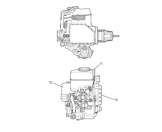
Text in Illustration *1 Brake Master Cylinder Reservoir
- Reservoir
- Brake Fluid Level Warning Switch
*2 Brake Booster with Accumulator Pump Assembly
- Brake Booster Pump Assembly
- Brake Booster Accumulator Assembly
- Relief Valve
*3 Master Cylinder Solenoid
- Brake Master Cylinder
- Switching Solenoid Valve
- Control Solenoid Valve
- Accumulator Pressure Sensor
- Master Cylinder Pressure Sensor
- Control Pressure Sensor (Models with Pre-crash Safety System)
- Skid Control ECU
- - 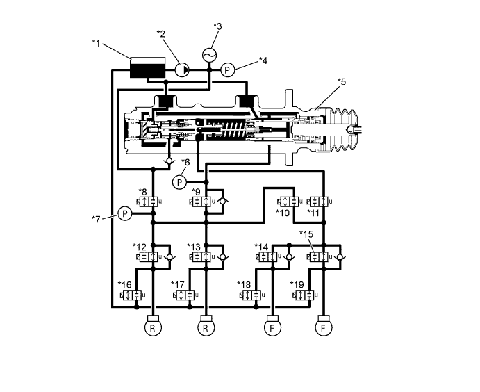
Text in Illustration (Hydraulic Circuit) *1 Reservoir *2 Brake Booster Pump Assembly *3 Brake Booster Accumulator Assembly *4 Accumulator Pressure Sensor *5 Brake Master Cylinder *6 Master Cylinder Pressure Sensor *7 Control Pressure Sensor (Models with Pre-crash Safety System) *8 Switching Solenoid Valve STR *9 Switching Solenoid Valve SREC *10 Switching Solenoid Valve SREA *11 Switching Solenoid Valve SMCF *12 Control Solenoid Valve SH *13 Control Solenoid Valve SR - -
-
-
Brake Master Cylinder
-
The master cylinder piston consists of a dual structure which uses pistons with 2 different diameters. The large diameter piston is used for normal braking to achieve a rigid braking feeling using short strokes. If a malfunction occurs in the brake booster with accumulator pump assembly, brake depression force activates the small diameter piston to ensure braking force for the front brake.
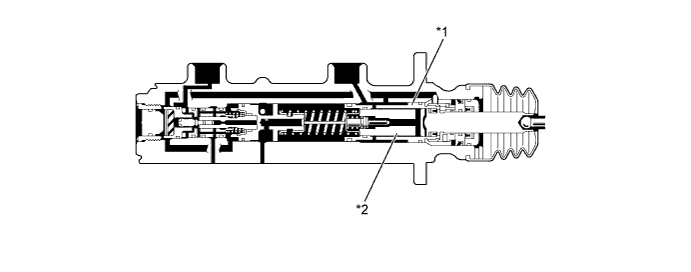
Text in Illustration *1 Master Cylinder Piston (Large Diameter) *2 Master Cylinder Piston (Small Diameter)
-
-
Brake Booster with Accumulator Pump Assembly
-
A plunger type pump is used for the brake booster pump assembly. This pump is driven by the pump motor, and generates high hydraulic pressure, and then supplies the hydraulic pressure to the brake booster accumulator assembly.
-
High-pressurized nitrogen gas is charged and sealed inside the brake booster accumulator assembly. In addition, a metallic bellows-formed tube is used, in order to enhance the gastight performance of the accumulator.
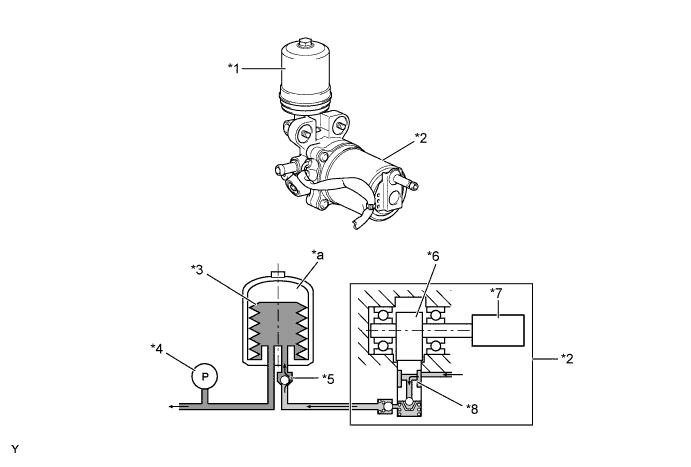
Text in Illustration *1 Brake Booster Accumulator Assembly *2 Brake Booster Pump Assembly *3 Bellows-formed Tube *4 Accumulator Pressure Sensor *5 Check Valve *6 Cam *7 Pump Motor *8 Pump Plunger *a Nitrogen Gas - -
-
-
-
OPERATION
-
Hydraulic Brake Booster Assembly
-
During normal braking, all solenoid valves are turned off.
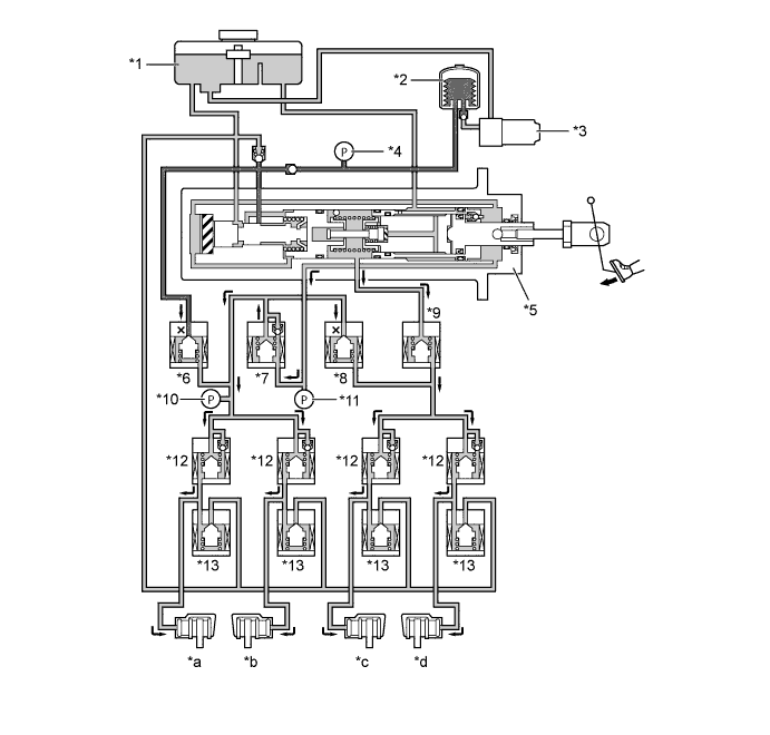
Text in Illustration *1 Reservoir *2 Brake Booster Accumulator Assembly *3 Brake Booster Pump Assembly *4 Accumulator Pressure Sensor *5 Brake Master Cylinder *6 Switching Solenoid Valve STR *7 Switching Solenoid Valve SREC *8 Switching Solenoid Valve SREA *9 Switching Solenoid Valve SMCF *10 Control Pressure Sensor (Models with Pre-crash Safety System) *11 Master Cylinder Pressure Sensor *12 Control Solenoid Valve SH *13 Control Solenoid Valve SR - - *a Rear LH *b Rear RH *c Front LH *d Front RH
-
-
Brake Master Cylinder
-
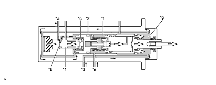
The brake pedal depression force is transmitted as follows; operation rod → power piston → master cylinder piston (small diameter).
-
The load setting of the master cylinder's return spring is higher than that of the regulator piston's return spring. Therefore, the regulator piston and spool valve will activate before the master cylinder is compressed.
-
In accordance with the activation of the spool valve, port A (between the reservoir and booster chamber) closes and port B (between the brake booster accumulator assembly and booster chamber) opens at the same time. The pressurized brake fluid from the brake booster accumulator assembly is introduced into the booster chamber, thus assisting the pedal depression force and increasing the pressure of the rear wheel cylinders. At the same time, the master cylinder center valve closes and the pressure of the front wheel cylinders increases.
-
During the initial stage of the brake operation, the booster pressure that is applied to the rubber reaction disc is small. Therefore, a return force in the rightward direction is not applied to the spool valve via the reaction rod.
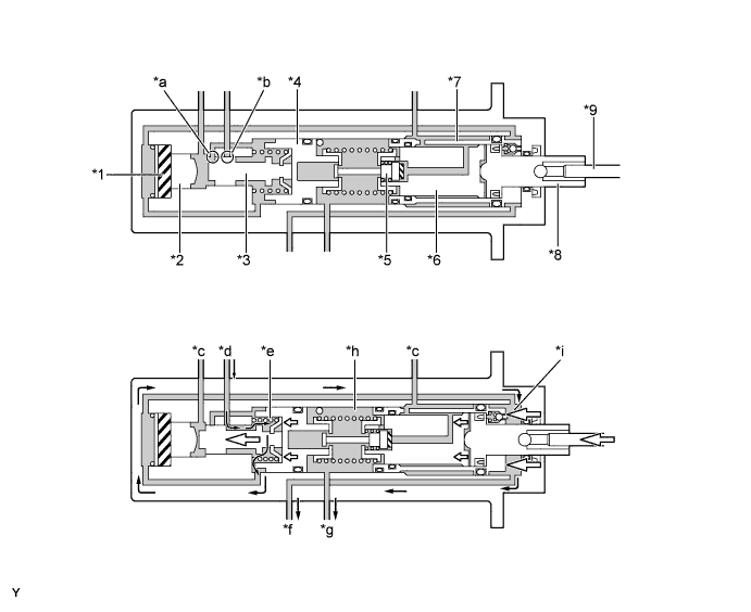
Text in Illustration *1 Reaction Disc *2 Reaction Rod *3 Spool Valve *4 Regulator Piston *5 Center Valve *6 Master Cylinder Piston (Small Diameter) *7 Master Cylinder Piston (Large Diameter) *8 Power Piston *9 Operation Rod - - *a Port A *b Port B *c To Reservoir *d From Brake Booster Accumulator Assembly *e Regulator Chamber *f To Rear Wheel Cylinder *g To Front Wheel Cylinder *h Master Cylinder Chamber *i Booster Chamber - - -
When the brake pedal is kept depressed, the pressure acting on the rubber reaction disc will increase. In this way, the rubber reaction disc is deformed, the pressure is transmitted via the reaction rod, and the reaction force is generated in the brake pedal. As a result, a variable servo mechanism, which optimizes the servo ratio in accordance with booster chamber pressure, is achieved.
Text in Illustration *1 Reaction Disc *2 Reaction Rod *3 Spool Valve - - -
When the brake pedal is in the holding condition, the pressure caused in both the master cylinder chamber and regulator chamber is equalized and both port A (between the reservoir and booster chamber) and port B (between the brake booster accumulator assembly and booster chamber) are closed.
Text in Illustration *a Port A *b Port B *c Regulator Chamber *d Master Cylinder Chamber -
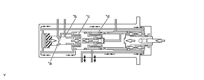
When the brake pedal is released from the holding condition and the brake pedal depression force is reduced, the pressure of the master cylinder chamber is reduced and the return (rightward) force is generated in the regulator piston. In this case, port A (between the reservoir and booster chamber) is opened by the spool valve and the pressure in the regulator chamber and booster chamber is reduced. By repeating this process, pressure reduction is achieved in accordance with the brake pedal depression force.
Text in Illustration *1 Spool Valve *2 Regulator Piston *a To Reservoir *b Port B *c Regulator Chamber *d From Rear Wheel Cylinder *e From Front Wheel Cylinder *f Master Cylinder Chamber *g Booster Chamber - - -
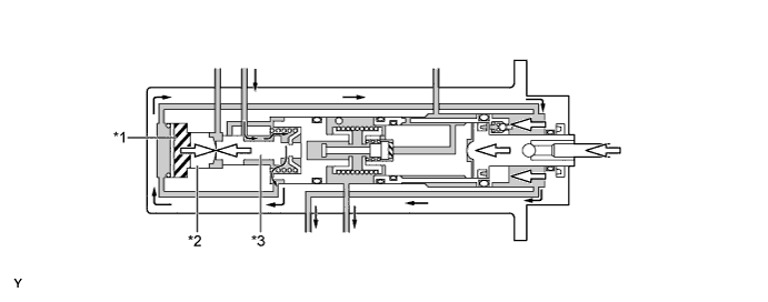
If the accumulator pressure is affected by any malfunction, no hydraulic pressure will be supplied to the booster chamber. For this reason, a power assist cannot be provided to the force that is applied via the brake pedal and the pressure to the rear brakes cannot be increased. Since there is no pressurized brake fluid in the large diameter master cylinder piston at this time, the piston does not move from the original position. For the front brake, the small diameter master cylinder is operated by the brake pedal depression force, the center valve is closed, and the pressure in the master cylinder chamber is increased, thus ensuring braking force.
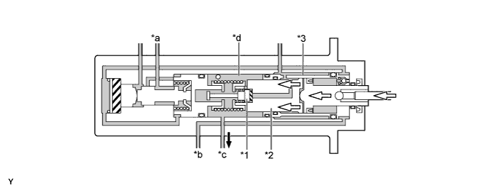
Text in Illustration *1 Center Valve *2 Master Cylinder Piston (Small Diameter) *3 Master Cylinder Piston (Large Diameter) - - *a From Brake Booster Accumulator Assembly *b To Rear Wheel Cylinder *c To Front Wheel Cylinder *d Master Cylinder Chamber -
If the front brake system malfunctions, the master cylinder piston is moved by the booster chamber pressure but the hydraulic pressure does not increase. The rear brake system operates the same as in the normal operation.
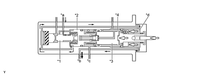
Text in Illustration *1 Spool Valve *2 Regulator Piston *3 Master Cylinder Piston (Small Diameter) *4 Master Cylinder Piston (Large Diameter) *a From Brake Booster Accumulator Assembly *b To Rear Wheel Cylinder *c To Front Wheel Cylinder *d Booster Chamber
-
-
Brake Booster with Accumulator Pump Assembly
-
The brake booster pump assembly operates based on the accumulator pressure sensor signal as shown in the timing chart below:
-
When the accumulator pressure drops to "pump on pressure", the skid control ECU operates the brake booster pump assembly.
-
When the accumulator pressure increases to "pump off pressure", the skid control ECU stops the brake booster pump assembly.
-
-
When the accumulator pressure drops below the "warning pressure" level, the skid control ECU illuminates each warning and indicator light, and sounds the skid control buzzer continuously.
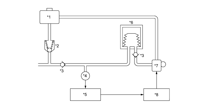
Text in Illustration *1 Reservoir *2 Relief Valve *3 Check Valve *4 Accumulator Pressure Sensor *5 Skid Control ECU *6 Brake Booster Accumulator Assembly *7 Brake Booster Pump Assembly *8 Motor Relay 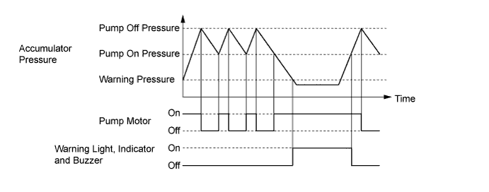
-
-