EMISSION CONTROL SYSTEM DETAILS
-
FUNCTION OF MAIN COMPONENTS
-
The main components of the emission control system are as follows:
Component Function Exhaust Emission System ECM Determines an optimal fuel injection volume based on the signals from various sensors. TWC Reduces CO, HC and NOx in the exhaust gas. Oxygen Sensor Detects the oxygen concentration in the exhaust emissions by measuring the electromotive force generated in the sensor itself. For details, see the 1GR-FE Engine Control. Air Fuel Ratio Sensor Air Injection System* Air Pump Assembly Uses a built-in DC motor to supply air to the air injection control valve. Air Injection Control Valve Introduces air that is pumped by the electric air pump into the exhaust manifold. Air Injection Control Driver -
Activated by the ECM, the air injection control driver actuates the air pump assembly and the air injection control valve.
-
Detects an input-output circuit failure at the air injection driver and transmits it to the ECM.
ECM -
Controls the air injection system in accordance with signals from the crankshaft position sensor, engine coolant temperature sensor, mass air flow meter and air pressure sensor.
-
Receives a failure detection signal from the air injection driver and stores a corresponding DTC in memory.
Evaporative Emission Control ECM Sends signals to the VSV (for EVAP) to control the purge flow. Charcoal Canister Sub-assembly Contains activated charcoal to absorb the fuel vapor created in the fuel tank. VSV (for EVAP) Opens in accordance with the signals from the ECM when the system is purging, in order to send the fuel vapor that was absorbed by the charcoal canister sub-assembly into the intake manifold. -
*: Models for compliant with EURO 5 emission regulations
-
-
-
FUNCTION
-
Air Injection System (Models for Compliant with EURO 5 Emission Regulations)
-
To ensure the proper warm-up performance of the Three-Way Catalytic converters (TWCs) after starting a cold engine, an air injection system is used.
-
This system is comprised of an air injection control driver, an air pump assembly, and 2 air injection control valves with built-in air pressure sensors.
-
The air injection control valves provided on each bank are controlled independently by the ECM and the air injection control driver.
-
The ECM estimates the amount of air injected to the TWCs based on signals from the mass air flow meter in order to regulate the air injection time.
-
-
-
CONSTRUCTION
-
Three-Way Catalytic converter (TWC)
-
TWCs are provided in the exhaust manifold of each bank and also in the exhaust center pipe.
-
An exhaust manifold with an integrated TWC is used for warm-up of the TWC.
-
An ultra thin-wall, high-cell density, ceramic type TWC is used for the exhaust manifold and a thin-wall, ceramic type TWC is used for the exhaust center pipe.
-
This TWC enables improved exhaust emissions by optimizing the cell density and the wall thickness.
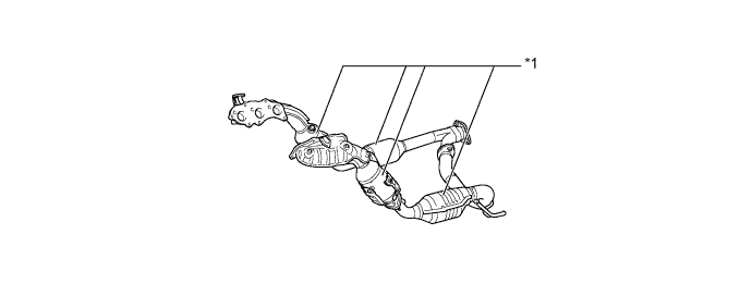
Text in Illustration *1 TWC - -
-
-
Air Pump Assembly (Models for Compliant with EURO 5 Emission Regulations)
-
An air pump assembly consists of a DC motor, an impeller, an air filter and a heater.
-
The DC motor is controlled by the air injection driver in accordance with signals from the ECM. The motor supplies air into an air injection control valve through the impeller.
-
A heater is provided to prevent operation faults in cold conditions.
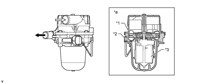
Text in Illustration *1 Impeller *2 Heater *3 DC Motor - - *a Cross Section - - 
To Air Injection Control Valve 
From Air Inlet
-
-
Air Injection Control Valve (Models for Compliant with EURO 5 Emission Regulations)
-
An air injection control valve consists of an air switching valve that switches the air flow and a reed valve that restricts the exhaust flow to one direction.
-
The air switching valve is a solenoid valve that is actuated by the ECM and air injection control driver.
-
An air pressure sensor is built into the corresponding air injection control valve.
-
The air injection control valves for bank 1 and bank 2 have the same basic structure and function.
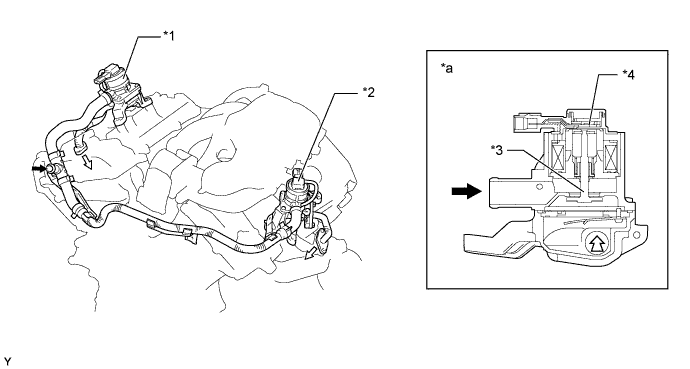
Text in Illustration *1 Air Injection Control Valve (Bank 1) *2 Air Injection Control Valve (Bank 2) *3 Air Switching Valve *4 Air Pressure Sensor *a Air Injection Control Valve (Bank 1) Cross Section - - From Air Pump Assembly To Air Injection Pipe
-
-
Air Pressure Sensor (Models for Compliant with EURO 5 Emission Regulations)
-
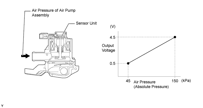
The air pressure sensor consists of a semiconductor, which has a silicon chip that changes its electrical resistance when pressure is applied to it. The sensor converts the pressure into an electrical signal, and sends it to the ECM in an amplified form.
-
The air pressure sensors for bank 1 and bank 2 have the same basic structure and function.
-
-
-
OPERATION
-
Air Pressure Sensor (Models for Compliant with EURO 5 Emission Regulations)
-
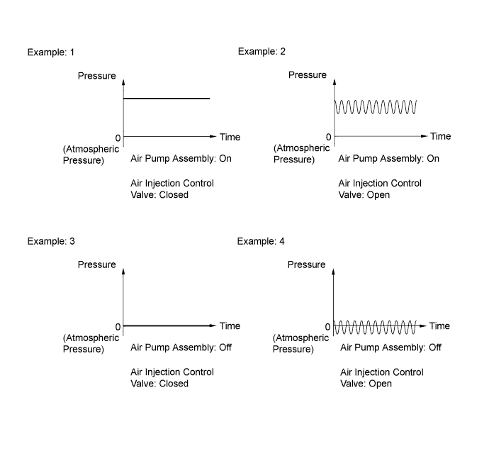
The ECM detects operation of the air injection system based on signals from the air pressure sensor as follows:
-
When the air pump assembly is on and the air injection control valve is closed, the pressure is stable.
-
When the air pump assembly is on and the air injection control valve is open, the pressure drops slightly and becomes unstable because of exhaust pulses.
-
When the air pump assembly is off and the air injection control valve is closed, the pressure remains at atmospheric pressure.
-
When the air pump assembly is off and the air injection control valve is open, the pressure drops below atmospheric pressure and becomes unstable because of exhaust pulses.
-
-
-
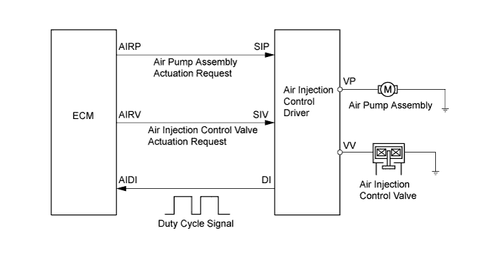
Air Injection Control Driver (Models for Compliant with EURO 5 Emission Regulations)
-
A semiconductor type air injection control driver is used. Activated by the ECM, this driver actuates the air pump assembly and the air injection control valve.
-
The air injection control driver also detects failures in the input and output circuits of the air injection driver and transmits the failure status to the ECM via duty cycle signals.
DI Terminal Output Condition AIRP AIRV Output (Duty Cycle Signal) Open circuit in line between AIDI and DI terminals. - - 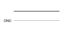
Failure in line between ECM terminals and air injection control driver. - - Output failure at air injection control driver. (Failure in air pump assembly actuation circuit) - - 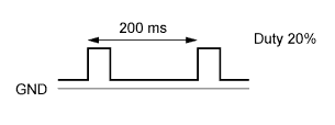
Output failure at air injection control driver. (Failure in air injection control valve actuation circuit) - - 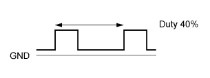
Overheat failure of air injection control driver. - - 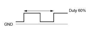
Normal On On 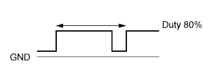
Off Off 
On Off Off On
-
-
Evaporative Emission Control System
-
Based on the signals from various sensors, the ECM opens and closes the VSV (for EVAP). Thus, it controls the purge flow of evaporative emissions (HC) in the charcoal canister sub-assembly in accordance with the engine conditions.
-
-