FUEL SYSTEM DETAILS
-
CONSTRUCTION
-
Fuel Injector Assembly
-
A 12-hole fuel injector assembly with optimized fuel flow amount is used to improve the atomization of fuel.
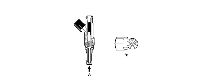
Text in Illustration *a View from A - -
-
-
Fuel Delivery Pipe Sub-assembly
-
The fuel delivery pipe sub-assembly is made of aluminum die-cast to reduce weight.
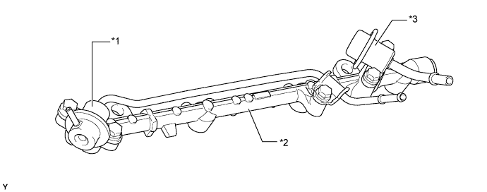
Text in Illustration *1 Pressure Regulator *2 Fuel Delivery Pipe Sub-assembly *3 Pulsation Damper - -
-
-
Fuel Tank
-
A multiplex layered plastic fuel tank is used for the fuel tank on the 5-door models with single fuel tank, and for the main fuel tank on the models with dual fuel tank.
-
A steel fuel tank is used for the fuel tank on 3-door models with single fuel tank, and for the sub fuel tank on 5-door models with dual fuel tank.
-
The multiplex layered plastic fuel tank consists of six layers of four types of materials, and one of those is a recyclable material to address environmental concerns.
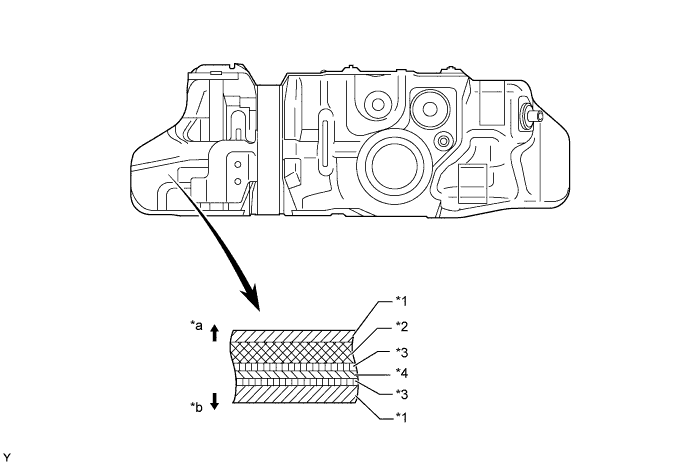
Text in Illustration *1 High Density Polyethylene (HDPE) *2 Regrind Material *3 Adhesive *4 Ethylene Vinyl Alcohol Copolymer (EVOH) *a Fuel Tank Outside *b Fuel Tank Inside -
On the models with dual fuel tank, a jet pump is provided in the fuel tank in order to automatically transfer fuel from the fuel sub tank to the fuel tank.
-
The fuel from the fuel pump passes through the orifice in the jet pump and returns to the fuel tank. Because the flow speed of the fuel from the fuel pump increases as it passes through the orifice, a vacuum is created near the exit of the orifice. This vacuum causes the fuel to be drawn from the fuel sub tank to the fuel tank.
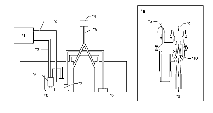
Text in Illustration *1 Engine *2 Return Tube *3 Main Tube *4 Fuel Inlet *5 Fuel Filler Pipe *6 Fuel Pump *7 Jet Pump *8 Main Fuel Tank *9 Sub Fuel Tank *10 Orifice *a Jet Pump Cross Section *b From Fuel Sub Tank *c From Fuel Pump *d To Fuel Tank
-
-
-
-
OPERATION
-
Sub Fuel Tank System
-
The fuel from the fuel pump actuates the jet pump in the fuel tank, in order to draw fuel from the sub fuel tank to the main fuel tank.
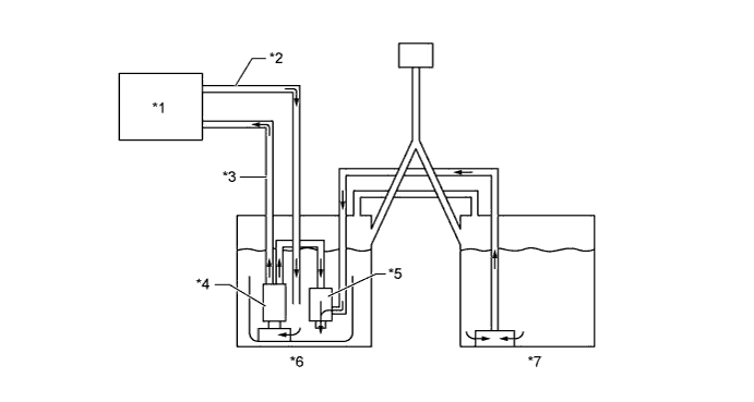
Text in Illustration *1 Engine *2 Return Tube *3 Main Tube *4 Fuel Pump *5 Jet Pump *6 Main Fuel Tank *7 Sub Fuel Tank - -
-
-