ENGINE UNIT DETAILS
-
CONSTRUCTION
-
Cylinder Head Cover
-
The cylinder head cover is made of plastic to reduce weight and noise.
-
Acrylic rubber, which excels in heat resistance and reliability, is used for the cylinder head cover gasket.
-
Baffle plates made of plastic are provided inside the cylinder head cover to reduce the consumption of engine oil through blow-by gas. The baffle plates are welded onto the cylinder head cover, and cannot be removed.
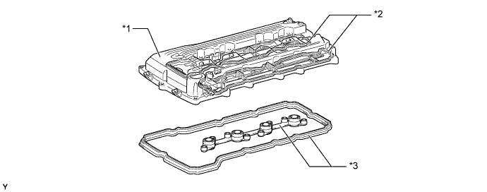
Text in Illustration *1 Cylinder Head Cover *2 Baffle Plate *3 Cylinder Head Cover Gasket - -
-
-
Cylinder Head Gasket
-
A steel-laminate type cylinder head gasket is used.
-
A shim has been added around the cylinder bore to increase the sealing surface, thus improving the sealing performance and durability.
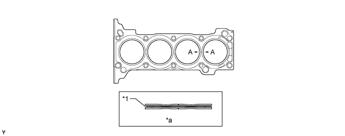
Text in Illustration *1 Shim - - *a A - A Cross Section - -
-
-
Cylinder Head
-
The cylinder head, which is made of aluminum alloy, contains a pentroof type combustion chamber. The spark plug has been located in the center of the combustion chamber in order to improve the engine's anti-knocking performance.
-
The angle between the intake and exhaust valves is narrowed and set at 22.85° to permit a compact cylinder head.
-
A cross-flow intake and exhaust layout is used to improve intake and exhaust efficiency.
-
A taper squish combustion chamber is used to improve anti-knocking performance and intake efficiency. In addition, engine performance and fuel economy have been improved.
-
Long nozzle type fuel injector assemblies are installed in the cylinder head to reduce the distance from the fuel injector to the intake valve, thus preventing the fuel from adhering to the intake port walls, and reducing exhaust emissions.
-
The routing of the water jacket in the cylinder head is optimized to achieve higher cooling performance.
-
An air injection port, which directs the air from the air pump assembly to the exhaust port of each cylinder, has been provided on top of the exhaust port on the models with the air injection system.
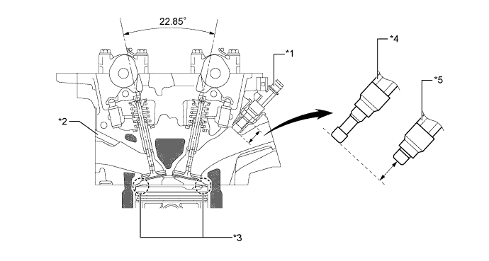
Text in Illustration *1 Fuel Injector Assembly *2 Air Injection Port *3 Taper Squish *4 Long Nozzle Type *5 Conventional Type - - 
Water Jacket - -
-
-
Cylinder Block
-
The cylinder block is made of cast iron, and the rib shape of each part has been optimized to increase rigidity while reducing vibration and noise.
-
A water passage is provided between the cylinder bores. By allowing the engine coolant to flow between the cylinder bores, this construction keeps the temperature of the cylinder walls uniform.
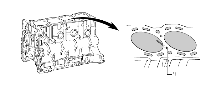
Text in Illustration *1 Water Passage - -
-
-
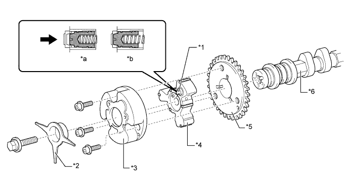
Balance Shaft
-
For in-line 4-cylinder engines, the main cause of vibration is imbalanced inertial force of reciprocating parts such as the pistons and connecting rods. The engine vibration has been reduced by using 2 balance shafts to cancel the imbalanced inertial force, thereby reducing engine noise (booming noise).
-
The 2 balance shafts are built into the cylinder block. Using a chain, sprockets and gears, both balance shafts rotate at twice the speed of the crankshaft with each balance shaft rotating in the opposite direction of the other.
-
The chain tensioner uses a spring and oil pressure to maintain proper chain tension at all times. A ratchet type non-return mechanism is also included.
-
The chain tensioner has 2 oil holes that spray engine oil for lubricating the balance shaft chain. Furthermore, they lubricate the timing chain that drives the camshaft.
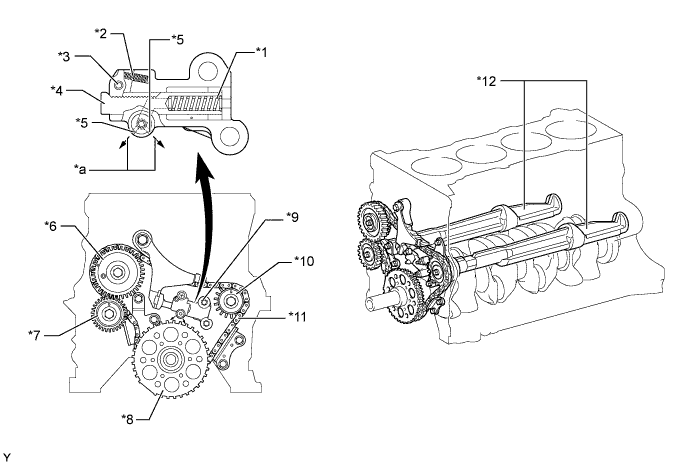
Text in Illustration *1 Spring *2 Cam Spring *3 Cam *4 Plunger *5 Oil Hole *6 Balance Shaft Drive Gear *7 Balance Shaft Driven Gear *8 Crankshaft Timing Sprocket *9 Chain Tensioner *10 Balance Shaft Timing Sprocket *11 Balance Shaft Chain *12 Balance Shaft *a Engine Oil - -
-
-
Piston
-
The pistons are made of aluminum alloy.
-
The tops of the pistons use a taper squish shape to achieve fuel combustion efficiency.
-
The piston skirt is coated with resin to reduce friction losses.
-
The groove of the top ring is coated with alumite to ensure abrasion resistance.
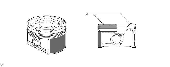
Text in Illustration *a Taper Squish Shape - - Resin Coating 
Anodic Oxide Coating
-
-
Connecting Rod and Connecting Rod Bearing
-
Connecting rods that have been forged for high strength are used for weight reduction.
-
Knock pins are used at the mating surfaces of the bearing caps of the connecting rod to minimize the shifting of the bearing caps during assembly.
-
Plastic region tightening bolts are used.
-
An aluminum bearing is used for the connecting rod bearings.
-
The lining surface of the connecting rod bearing has been micro-grooved to achieve an optimal amount of oil clearance. As a result, cold-engine cranking performance has been improved and engine vibrations have been reduced.
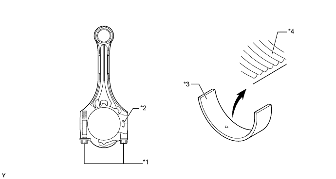
Text in Illustration *1 Plastic Region Tightening Bolt *2 Knock Pin *3 Connecting Rod Bearing *4 Micro-grooved Surface
-
-
Crankshaft and Crankshaft Bearing
-
The crankshaft has 5 journals and 8 balance weights.
-
All pin and journal fillets are roll-finished to maintain adequate strength.
-
The crankshaft bearing is made of aluminum alloy.
-
The crankshaft bearing caps are tightened using 2 plastic region tightening bolts for each journal.
-
Similar to the connecting rod bearings, the lining surface of the crankshaft bearings has been micro-grooved to achieve an optimal amount of oil clearance. As a result, cold-engine cranking performance has been improved and engine vibrations have been reduced.
-
The upper main bearing has an oil groove around its inside circumference.
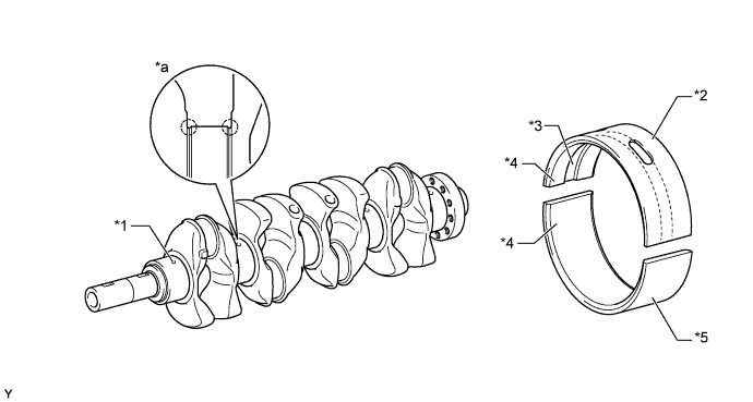
Text in Illustration *1 Oil Hole *2 Upper Main Bearing *3 Oil Grooved *4 Micro-grooved *5 Lower Main Bearing - - *a Roll-finished - -
-
-
Crankshaft Pulley
-
The rigidity of the crankshaft pulley with its built-in torsional damper rubber reduces noise.

Text in Illustration *1 Torsional Damper Rubber - -
-
-
Oil Pan
-
No. 1 oil pan is made of aluminum alloy.
-
No. 2 oil pan is made of steel.
-
No. 1 oil pan is secured to the cylinder block and the transmission in order to increase rigidity.
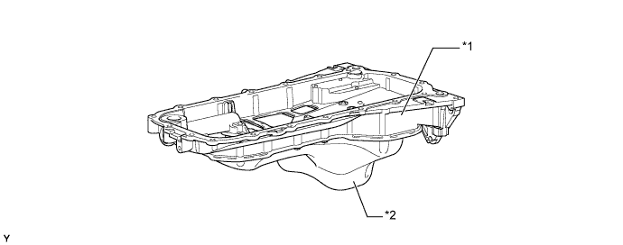
Text in Illustration *1 No. 1 Oil Pan *2 No. 2 Oil Pan
-
-
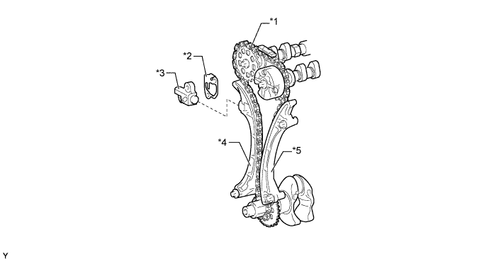
Valve Mechanism
-
This engine uses valve rocker arm sub-assemblies with built-in needle bearings. This reduces the friction that occurs between the cams and the roller rocker arms when the valves are pushed down, thus improving fuel economy.
-
A valve lash adjuster assembly, which maintains a constant zero valve clearance through the use of oil pressure and spring force, is used.
-
The intake camshaft and exhaust camshaft driven by the crankshaft via the timing chain.
-
The VVT-i system is used to achieve low fuel consumption and higher engine performance to reduce exhaust emissions.
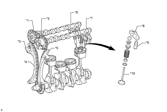
Text in Illustration *1 Timing Chain *2 VVT-i Controller *3 Chain Tensioner *4 Chain Slipper *5 Chain Damper *6 Exhaust Camshaft *7 Intake Camshaft *8 Valve Rocker Arm Sub-assembly *9 Valve Lash Adjuster Assembly *10 Valve
-
-
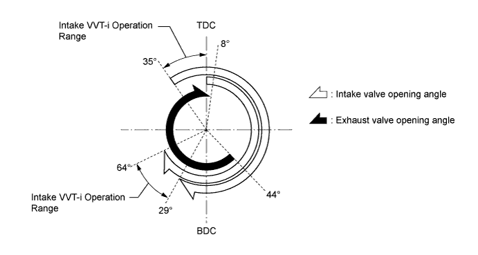
Valve Timing
-
Camshaft
-
An oil passage is provided in the intake camshaft in order to supply engine oil pressure to the VVT-i system.
-
A VVT-i controller is installed on the front of the intake camshaft to vary the timing of the intake valves.
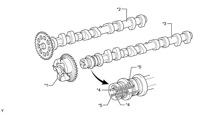
Text in Illustration *1 VVT-i Controller *2 Exhaust Camshaft *3 Intake Camshaft *4 Oil Passage (Advance) *5 Oil Passage (Retard) - -
-
-
VVT-i Controller
-
This controller consists of a housing driven by the timing chain and a vane coupled with the intake camshaft. The oil pressure sent from the advance or retard side path at the intake camshaft causes rotation in the VVT-i controller vane circumferential direction to vary the intake valve timing continuously.
-
When the engine is stopped, the intake camshaft will be in the most retarded state to ensure startability. When hydraulic pressure is not applied to the VVT-i controller immediately after the engine has started, the lock pin locks the movement of the VVT-i controller to prevent a knocking noise. Thereafter, when hydraulic pressure is applied to the VVT-i controller, the lock pin is released.
Text in Illustration *1 Lock Pin *2 Timing Rotor *3 Outer Housing *4 Vane (Coupled to Intake Camshaft) *5 Timing Chain Sprocket *6 Intake Camshaft *a Engine Operating *b Engine Stopped 
Oil Pressure - -
-
-
Timing Chain and Chain Tensioner
-
A high-strength roller chain with a 9.525 mm (0.375 in.) pitch is used to make the engine more compact and to ensure the reliability of the timing chain.
-
The chain tensioner uses a spring and oil pressure to maintain proper chain tension at all times. The chain tensioner suppresses noise generated by the timing chain.
-
A ratchet type non-return mechanism is used in the chain tensioner.
Text in Illustration *1 Timing Chain *2 Chain Tensioner Gasket *3 Chain Tensioner *4 Chain Slipper *5 Chain Damper - -
-
-
Valve Lash Adjuster Assembly
-
The valve lash adjuster assembly, which is located at the fulcrum (pivot point) of the valve rocker arm sub-assemblies, consists primarily of a plunger, a plunger spring, a check ball, and a check ball spring.
-
The engine oil supplied from the cylinder head and the built-in spring actuate the valve lash adjuster assembly. The oil pressure and the spring force, that act on the plunger, push the valve rocker arm sub-assembly against the cam, in order to adjust the clearance between the valve stem and rocker arm. This prevents the generation of noise during the opening and closing of the valves. As a result, engine noise has been reduced.
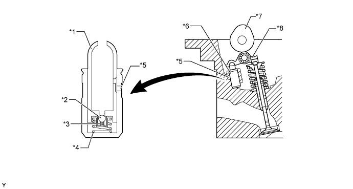
Text in Illustration *1 Plunger *2 Check Ball *3 Check Ball Spring *4 Plunger Spring *5 Oil Passage *6 Valve Lash Adjuster Assembly *7 Cam *8 Valve Rocker Arm Sub-assembly
-
-
Timing Chain Cover
-
The components listed below have been integrated in the timing chain cover to reduce the number of parts (water pump swirl chamber, thermostat housing, oil pump housing, alternator bracket and power steering vane pump bracket).
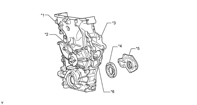
Text in Illustration *1 Alternator Bracket *2 Water Pump *3 Power Steering Vane Pump Bracket *4 Oil Pump *5 Oil Pump Housing *6 Thermostat Housing
-
-
V-ribbed Belt
-
Accessory components are driven by a serpentine belt consisting of a single V-ribbed belt. It reduces the overall engine length, weight and number of engine parts.
-
An automatic tensioner eliminates the need for tension adjustment.
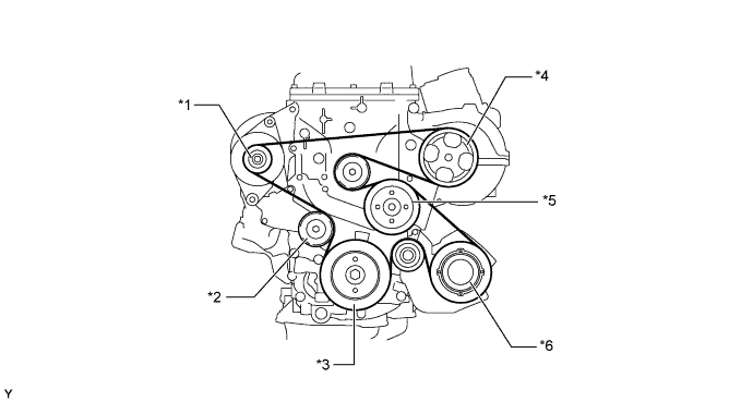
Text in Illustration *1 Alternator Pulley *2 Automatic Tensioner *3 Crankshaft Pulley *4 Power Steering Pump Pulley *5 Water Pump Pulley *6 Air Conditioning Compressor Pulley
-
-
-
OPERATION
-
Balance Shaft
-
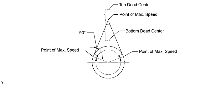
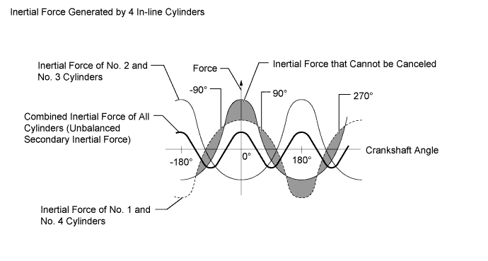
In the in-line 4-cylinder engine, the crankshaft angle for No. 1 and No. 4 cylinders are at the exact opposite (180°) positions of No. 2 and No. 3 cylinders. Therefore, the inertial force of the pistons and the connecting rods of the former 2 cylinders and of the latter 2 cylinders almost cancel each other out. However, because the position at which the piston reaches its maximum speed is located toward the top dead center from the center of the stroke, the upward inertial force is greater than the downward inertial force. This unbalanced secondary inertial force is generated twice for each rotation of the crankshaft.
-
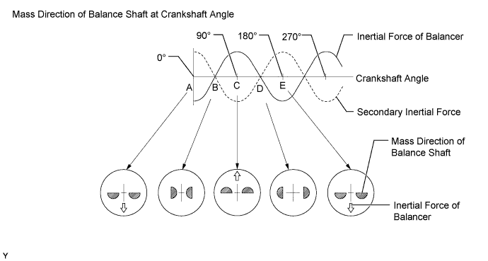
To cancel the unbalanced secondary inertial force, 2 balance shafts are rotated twice for each rotation of the crankshaft and generate inertial force in the opposite direction. Also, in order to cancel the inertial force generated by the balance shaft itself, the balance shaft actually consists of 2 shafts rotating in opposite directions.
-
-