ENGINE UNIT DETAILS
-
CONSTRUCTION
-
Cylinder Head
-
The combustion efficiency is enhanced by optimizing the swirl chamber shape. This improvement helps reduce the generation of CO, HC, and black smoke.
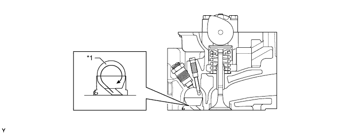
Text in Illustration *1 Swirl Chamber - -
-
-
Cylinder Head Gasket
-
A 4-layer steel-laminate type cylinder head gasket, which excels in sealing performance and heat resistance, is used.
-
Gaskets of different thicknesses are selected in accordance with the amount of protrusion of the pistons to reduce variations in the compression ratio.
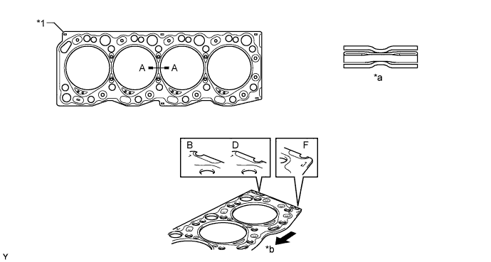
Text in Illustration *1 Cylinder Head Gasket - - *a A - A Cross Section *b Front Tech Tips
There are 3 sizes of new cylinder head gasket, marked B, D, or F in accordance with piston protrusion. For details, refer to the corresponding Repair Manual for this model.
-
-
Cylinder Block
-
The portion of the No. 3 crankshaft bearing journal has been reinforced to reduce noise and improve rigidity.
-
The crank position sensor installation boss is provided on the cylinder block.
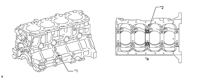
Text in Illustration *1 Crank Position Sensor Installation Boss *2 No. 3 Crankshaft Bearing Journal *a View from Bottom Side - -
-
-
Piston
-
The piston is made of aluminum alloy which excels in high-temperature strength. The skirt portion has been tin-plated to achieve wear resistance.
-
A cooling channel has been provided at the upper part of the piston to improve the cooling performance.
-
To improve the wear resistance of the top ring groove, a Fiber Reinforced Metal (FRM) ring carrier is used.
-
The surfaces of the No. 1 and No. 2 piston rings and of the oil ring have been gas-nitrided to improve their wear resistance.
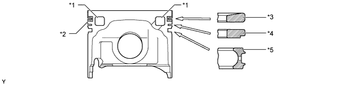
Text in Illustration *1 Cooling Channel *2 FRM Ring Carrier *3 No. 1 Compression Ring *4 No. 2 Compression Ring *5 Oil Ring - -
-
-
Connecting Rod Sub-assembly
-
The connecting rod is made of high-strength steel to ensure proper strength.
-
A tapered shape has been given to the small end of the connecting rod to reduce weight.
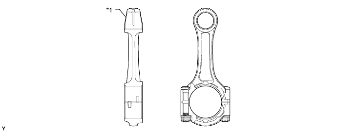
Text in Illustration *1 Tapered Shape - -
-
-
Crankshaft
-
The crankshaft has 5 journals and 8 balance weights.
-
A protrusion has been provided on the crankshaft to generate a crankshaft position signal.
-
The balance weights have been streamlined in order to reduce their friction loss by the engine oil during high rpm operation.
-
The fillet has been roll-finished to improve rigidity.
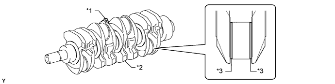
Text in Illustration *1 Protrusion *2 Balance Weight *3 Roll-finished - -
-
-
Crankshaft Pulley
-
The rigidity of the torsional damper rubber is used to reduce noise.

Text in Illustration *1 Torsional Damper Rubber - -
-
-
Valve Mechanism
-
A direct drive OHC is used for the valve drive mechanism.
-
Each cylinder has 1 intake valve and 1 exhaust valve.
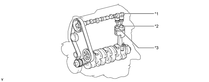
Text in Illustration *1 Camshaft *2 Intake Valve *3 Exhaust Valve - - 
-
-
Camshaft
-
The cam nose has been chill-treated to increase its abrasion resistance.

Text in Illustration *1 Camshaft *2 Cam Nose
-
-
Intake and Exhaust Valves and Valve Lifter
-
Heat-resistant steel is used for the intake and exhaust valves.
-
Unequal-pitch springs with anomalous cross sections are used to improve the surge resistance of the valve springs.
-
The adjusting shim has been located directly above the valve lifter. This construction allows the adjusting shim to be replaced without removing the camshaft, which improves the serviceability during valve clearance adjustment.
-
A cutout is provided in the valve lifter to improve the serviceability of the adjusting shims when replacement is required.
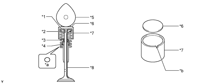
Text in Illustration *1 Spring Retainer *2 Spring Retainer Lock *3 Valve Spring *4 Oil Seal *5 Camshaft *6 Adjusting Shim *7 Valve Lifter *8 Valve *a Spring Cross Section *b Cutout Tech Tips
The adjusting shims are available in 17 sizes in increments of 0.05 mm (0.002 in.), from 2.50 (0.098 in.) to 3.30 (0.130 in.). For details, refer to the corresponding Repair Manual for this model.
-
-