ENGINE UNIT DETAILS
-
CONSTRUCTION
-
Cylinder Head Cover
-
A lightweight yet high-strength aluminum cylinder head cover is used.
-
An oil delivery pipe is installed inside each cylinder head cover. This ensures lubrication to the sliding parts of the valve rocker arm sub-assemblies, improving reliability.
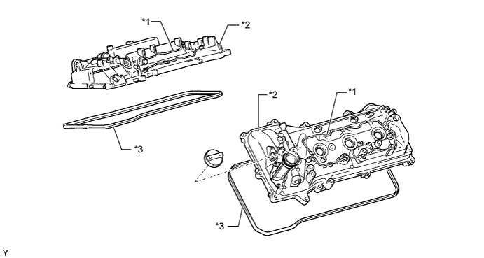
Text in Illustration *1 Oil Delivery Pipe *2 Cylinder Head Cover *3 Cylinder Head Cover Gasket - -
-
-
Cylinder Head Gasket
-
A steel-laminate type cylinder head gasket is used.
-
A shim has been added around the cylinder bore to increase the sealing surface, thus improving the sealing performance and durability.
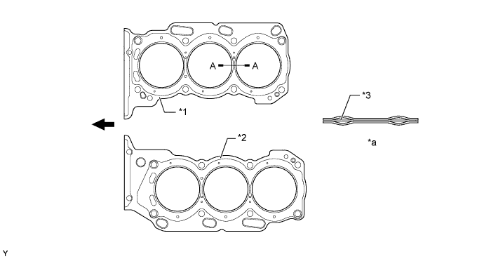
Text in Illustration *1 Cylinder Head Gasket RH *2 Cylinder Head Gasket LH *3 Shim - - *a A - A Cross Section - - 
Engine Front - -
-
-
Cylinder Head
-
The cylinder head, which is made of aluminum, contains a pentroof type combustion chamber. The spark plug has been located in the center of the combustion chamber in order to improve the engine's anti-knocking performance.
-
The intake ports are on the inside and the exhaust ports are on the outside of the left and right banks respectively.
-
Upright intake ports are used to improve the intake efficiency.
-
A taper squish combustion chamber is used to improve anti-knocking performance and intake efficiency. In addition, engine performance and fuel economy have been improved.
-
A siamese type intake port is used to reduce the overall surface area of the intake port walls. This prevents the fuel from adhering onto the intake port walls, thus reducing HC exhaust emissions.
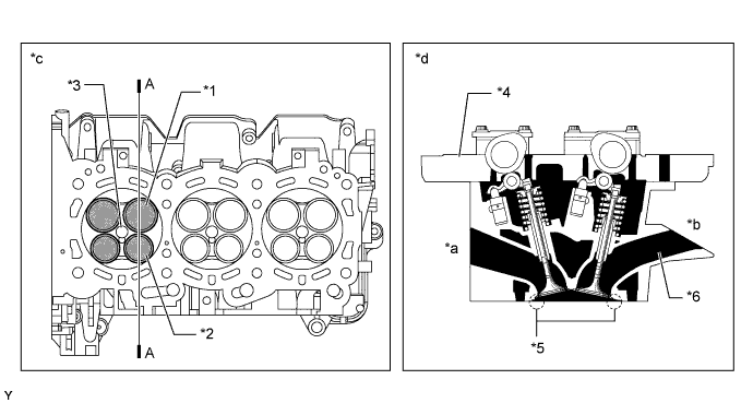
Text in Illustration *1 Intake Valve *2 Exhaust Valve *3 Spark Plug Hole *4 Camshaft Housing *5 Taper Squish *6 Upright Intake Port *a Exhaust Side *b Intake Side *c Bottom Side View *d A - A Cross Section Tech Tips
The difference between a siamese type intake port and independent type one is shown in the illustration.
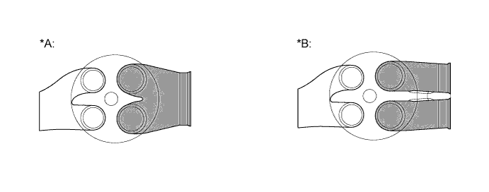
Text in Illustration *A Siamese Type *B Independent Type
-
-
Cylinder Block
-
The cylinder block is made of aluminum alloy.
-
The cylinder block has a bank angle of 60°, a bank offset of 36.6 mm (1.441 in.) and a bore pitch of 105.5 mm (4.15 in.), resulting in a compact block in its length and width even for its displacement.
-
Spiny-type liners are used.
-
Installation bosses of the two knock control sensors are located on the inner side of the left and right banks.
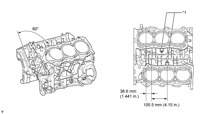
Text in Illustration *1 Knock Control Sensor Boss - - -
A water passage is provided between the cylinder bores. By allowing the engine coolant to flow between the cylinder bores, this construction keeps the temperature of the cylinder walls uniform.
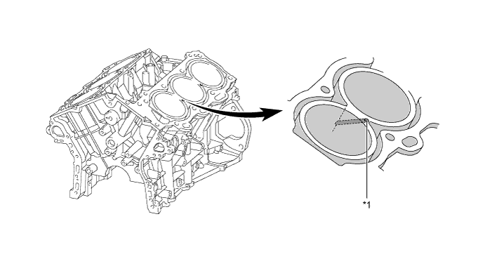
Text in Illustration *1 Water Passage - - -
The liners are the spiny-type which have been manufactured so that their casting exteriors form large irregular surfaces in order to enhance the adhesion between the liners and the aluminum cylinder block. The enhanced adhesion helps heat dissipation, resulting in a lower overall temperature and heat deformation of the cylinder bores.
-
The shape of the cross-hatching of the liner surface has been optimized to improve oil retention performance, resulting in reduced friction.
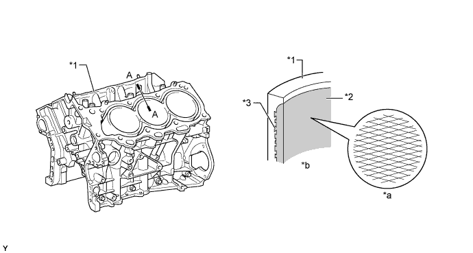
Text in Illustration *1 Cylinder Block *2 Liner *3 Irregularly Shaped Outer Casting Surface of Liner - - *a Enlarged View of Cross-hatching *b A - A Cross Section -
The temperature in the intake side of the cylinder bore tends to be lower. For this reason, a wide cylinder block water jacket spacer covers the cylinder bores in order to suppress the flow of the engine coolant and prevent excessive cooling. On the other hand, the temperature of the exhaust side of the cylinder bore tends to be higher. A cylinder block water jacket spacer covers the lower area of the cylinder bores in order to direct the engine coolant to the upper area of the cylinder bores where the temperature is higher. This makes the temperature around the cylinder bores more uniform. As a result, the viscosity of the engine oil (which lubricates the area between the wall surface of the cylinder bore and the piston) decreases, thus reducing friction between the cylinder bore and the piston.
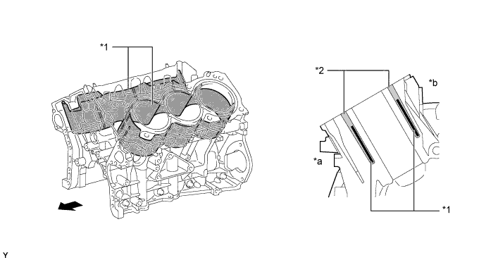
Text in Illustration *1 Cylinder Block Water Jacket Spacer *2 Water Jacket *a Exhaust Side *b Intake Side Engine Front - -
-
-
Piston
-
The pistons are made of aluminum alloy.
-
The tops of the pistons use a taper squish shape to achieve fuel combustion efficiency.
-
The piston skirt is coated with resin to reduce friction losses.
-
The groove of the top ring is coated with alumite to ensure abrasion resistance.
-
By increasing the machining precision of the cylinder bore diameter in the block, only one size of piston is required.
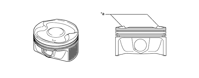
Text in Illustration *a Taper Squish Shape - - 
Resin Coating 
Anodic Oxide Coating
-
-
Connecting Rod and Connecting Rod Bearing
-
Connecting rods that have been forged for high strength are used for weight reduction.
-
Knock pins are used at the mating surfaces of the bearing caps of the connecting rod to minimize the shifting of the bearing caps during assembly.
-
Plastic region tightening bolts are used.
-
An aluminum bearing is used for the connecting rod bearings.
-
The lining surface of the connecting rod bearing has been micro-grooved to achieve an optimal amount of oil clearance. As a result, cold-engine cranking performance has been improved and engine vibrations have been reduced.
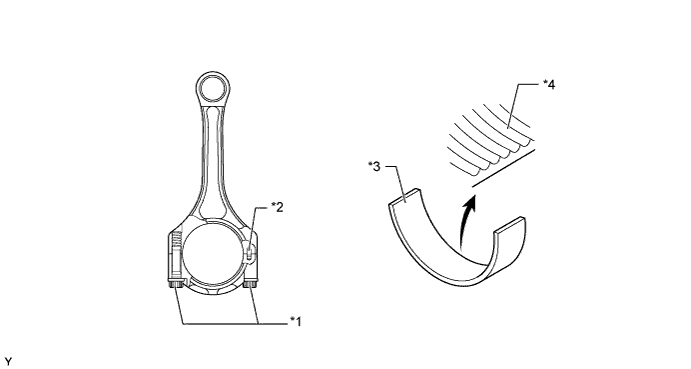
Text in Illustration *1 Plastic Region Tightening Bolt *2 Knock Pin *3 Connecting Rod Bearing *4 Micro-grooved Surface
-
-
Crankshaft
-
A crankshaft made of forged steel, which excels in rigidity and wear resistance, is used.
-
The crankshaft has 4 main bearing journals and 5 balance weights.
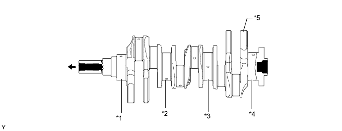
Text in Illustration *1 No. 1 Journal *2 No. 2 Journal *3 No. 3 Journal *4 No. 4 Journal *5 Balance Weight - - Engine Front - -
-
-
Crankshaft Bearing and Crankshaft Bearing Cap
-
The crankshaft main bearings are made of aluminum alloy.
-
Similar to the connecting rod bearings, the lining surface of the crankshaft bearings is micro-grooved to achieve an optimal amount of oil clearance. As a result, cold-engine cranking performance is improved and engine vibration is reduced.
-
The upper crankshaft bearings have an oil groove around the inside circumference.
-
The crankshaft bearing caps are tightened using 4 plastic region tightening bolts for each journal. In addition, each cap is tightened laterally to improve its reliability.
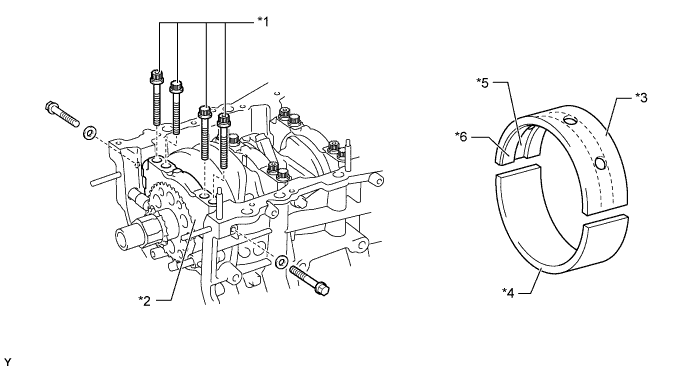
Text in Illustration *1 Plastic Region Tightening Bolt *2 Crankshaft Bearing Cap *3 Upper Crankshaft Bearing *4 Lower Crankshaft Bearing *5 Oil Groove *6 Micro-grooved Surface
-
-
Crankshaft Pulley
-
The rigidity of the crankshaft pulley with its built-in torsional damper rubber reduces noise.

Text in Illustration *1 Torsional Damper Rubber - -
-
-
Oil Pan
-
No. 1 oil pan is made of aluminum alloy.
-
No. 2 oil pan is made of steel.
-
An oil passage has been integrated into No. 1 oil pan to simplify the construction of the oil strainer.
-
No. 1 oil pan is secured to the cylinder block and the torque converter housing in order to increase rigidity.
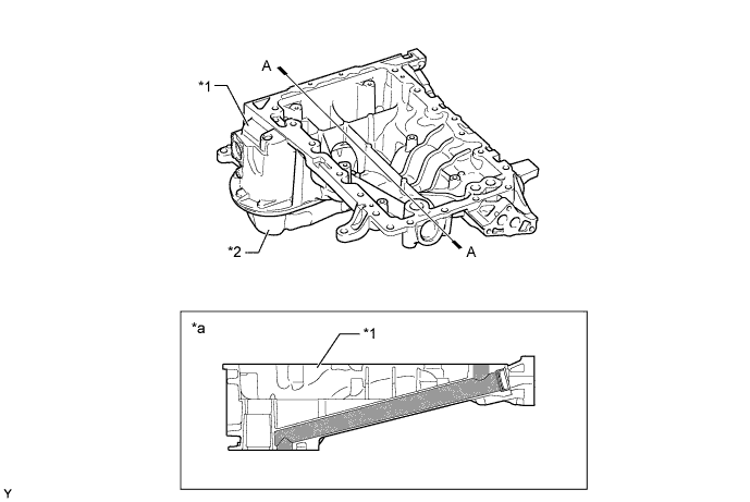
Text in Illustration *1 No. 1 Oil Pan *2 No. 2 Oil Pan *a A - A Cross Section - - Oil Passage - -
-
-
Valve Mechanism
-
Each cylinder of this engine has 2 intake valves and 2 exhaust valves. Intake and exhaust efficiency is increased due to the larger total port areas.
-
This engine uses valve rocker arms with built-in needle bearings. This reduces the friction that occurs between the cams and the valve rocker arms when the valves are pushed down, thus improving fuel economy.
-
A valve lash adjuster assembly, which maintains a constant zero valve clearance through the use of oil pressure and spring force, is used.
-
The intake camshafts are driven by the crankshaft via the primary timing chain. The exhaust camshafts are each driven by the intake camshaft of their respective bank via a secondary chain.
-
This engine has the Dual Variable Valve Timing-intelligent (Dual VVT-i) system which controls the intake camshafts and exhaust camshafts to provide optimal valve timing in accordance with driving conditions. With this use, lower fuel consumption, higher engine performance, and fewer exhaust emissions have been achieved.
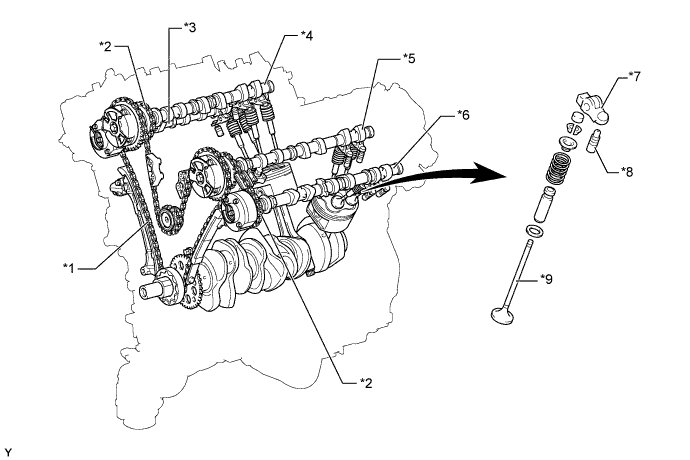
Text in Illustration *1 Primary Timing Chain *2 Secondary Timing Chain *3 No. 2 Camshaft (Exhaust) *4 No. 1 Camshaft (Intake) *5 No. 3 Camshaft (Intake) *6 No. 4 Camshaft (Exhaust) *7 Valve Rocker Arm Sub-assembly *8 Valve Lash Adjuster Assembly *9 Valve - -
-
-
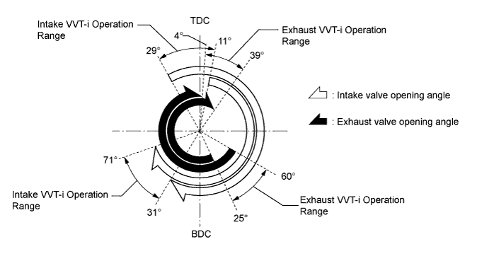
Valve Timing
-
Camshaft
-
The camshafts are made of cast iron alloy.
-
Oil passages are provided on the intake and exhaust camshafts in order to supply engine oil to the VVT-i system.
-
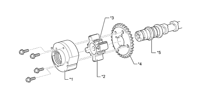
VVT-i controllers are installed on the front of the camshafts to vary the timing of the intake and exhaust valves.
-
Together with the use of the valve rocker arm sub-assemblies, the cam profile has been modified. This results in increased valve lift when the valve begins to open and as it finishes closing, helping to achieve enhanced output performance.

Text in Illustration *1 VVT-i Controller (Exhaust RH) *2 No. 2 Camshaft (Exhaust) *3 No. 1 Camshaft (Intake) *4 Timing Rotor *5 VVT-i Controller (Intake RH) *6 VVT-i Controller (Intake LH) *7 No. 3 Camshaft (Intake) *8 No. 4 Camshaft (Exhaust) *9 VVT-i Controller (Exhaust LH) *10 Modified Profile of Camshaft Lobe *a Increased Valve Lift - -
-
-
VVT-i Controller (Intake)
-
This controller consists of an outer housing driven by the timing chain sprocket, and a vane coupled to each camshaft.
-
The intake side uses a VVT-i controller with 3 vanes.
-
When the engine stops, each intake side VVT-i controller is locked at the most retarded angle by its lock pin. This ensures excellent engine startability.
-
The oil pressure sent from the advance or retard side passages of the intake camshafts causes rotation of the vane relative to the timing chain sprocket, to vary the valve timing continuously.
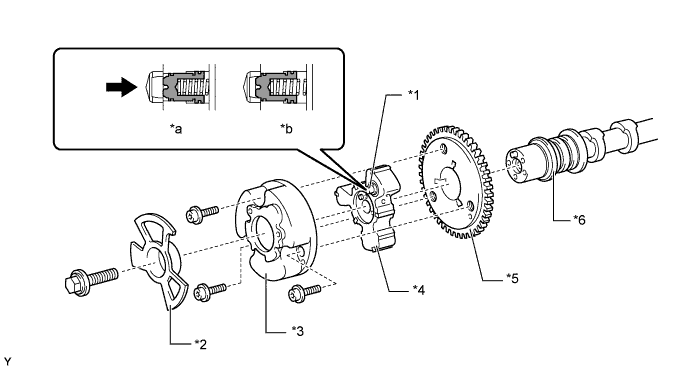
Text in Illustration *1 Lock Pin *2 Timing Rotor *3 Outer Housing *4 Vane (Coupled to Intake Camshaft) *5 Timing Chain Sprocket *6 Intake Camshaft *a Engine Operating *b Engine Stopped Oil Pressure - -
-
-
VVT-i Controller (Exhaust)
-
This controller consists of an outer housing that is driven by the timing chain sprocket, and a vane that is coupled to each camshaft.
-
The exhaust side uses a VVT-i controller which uses a vane with 4 lobes.
-
When the engine stops, the exhaust side VVT-i controller is locked at the most advanced angle. This ensures excellent engine startability.
-
The oil pressure sent from the advance or retard side passages of the exhaust camshafts causes rotation of the vane relative to the timing chain sprocket, to vary the valve timing continuously.
-
An advance assist spring is provided on the exhaust side VVT-i controller. This helps to apply torque in the advance angle direction so that the vane lock pin securely engages with the housing when the engine stops.
Text in Illustration *1 Outer Housing *2 Vane (Coupled to Exhaust Camshaft) *3 Lock Pin *4 Timing Chain Sprocket *5 Exhaust Camshaft - -
-
-
Timing Chain and Chain Tensioner
-
The primary and secondary timing chains are roller chains with a pitch of 9.525 mm (0.375 in.).
-
A chain tensioner is provided for each primary timing chain and secondary timing chain in each bank.
-
Both types of chain tensioner use a spring and oil pressure to maintain proper chain tension at all times. They suppress noise generated by the chains.
-
The chain tensioner for the primary timing chain is a ratchet type with a non-return mechanism. Furthermore, an oil pocket creates oil pressure when the engine is started, and simultaneously applies oil pressure to the chain tensioner. This prevents the timing chain from flapping and reduces noise.
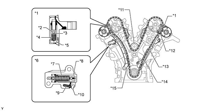
Text in Illustration *1 Chain Tensioner (Secondary) *2 Ball *3 Ball Spring *4 Main Spring *5 Plunger *6 Chain Tensioner (Primary) *7 Spring *8 Plunger *9 Cam Spring *10 Cam *11 Idle Sprocket *12 Secondary Timing Chain *13 Primary Timing Chain *14 Chain Damper *15 Chain Slipper - -
-
-
Valve Lash Adjuster Assembly
-
The valve lash adjuster assembly, which is located at the fulcrum (pivot point) of the valve rocker arm sub-assemblies, consists primarily of a plunger, a plunger spring, a check ball, and a check ball spring.
-
The engine oil supplied from the cylinder head and the built-in spring actuate the valve lash adjuster assembly. The oil pressure and the spring force, that act on the plunger, push the valve rocker arm sub-assembly against the cam, in order to adjust the clearance between the valve stem and rocker arm. This prevents the generation of noise during the opening and closing of the valves. As a result, engine noise has been reduced.
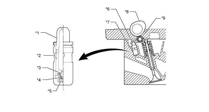
Text in Illustration *1 Plunger *2 Oil Passage *3 Check Ball *4 Check Ball Spring *5 Plunger Spring *6 Valve Lash Adjuster Assembly *7 Oil Passage *8 Cam *9 Valve Rocker Arm Sub-assembly - -
-
-
V-ribbed Belt
-
Accessory components are driven by a serpentine belt consisting of a single V-ribbed belt. It reduces the overall engine length, weight and number of engine parts.
-
An automatic tensioner eliminates the need for tension adjustment.
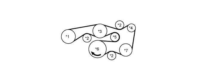
Text in Illustration *1 Power Steering Pump Pulley *2 Belt Idler *3 Water Pump Pulley *4 Alternator Pulley *5 Idler Pulley for Automatic Tensioner *6 Crankshaft Pulley *7 Air Conditioning Compressor Pulley - - -
The tension of the V-ribbed belt is properly maintained by the tension spring that is enclosed in the belt tensioner.
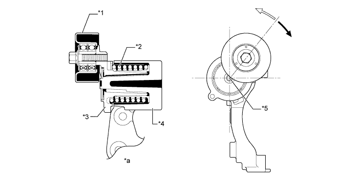
Text in Illustration *1 Idler Pulley *2 Spring *3 Arm *4 Bracket *5 Fulcrum - - *a Cross Section - - Belt Tension Direction 
Belt Pulling Direction
-
-