AIR CONDITIONING SYSTEM DETAILS
-
SYSTEM CONTROL
-
The air conditioning system uses the following controls.
Control Function Neural Network Control This control is capable of performing complex control by artificially simulating the information processing method of the nervous system of living organisms in order to establish a complex input/output relationship that is similar to a human brain. Automatic Recirculation Control Automatically changes the air inlet mode to fresh air or recirculate mode according to the level of harmful elements in the outside air, cabin temperature, and outside temperature. Manual Control The air conditioning amplifier assembly controls the damper positions (air inlet control servo motor, air mix control servo motor and mode control servo motor) and blower speed in accordance with the positions of the switches (temperature control switch, blower switch, mode control switch and inlet control switch). Outlet Air Temperature Control Based on the temperature set at the temperature control switch, the neural network control calculates the outlet air temperature based on the input signals from various sensors. Left and Right Independent Control The temperature setting for the driver and front passenger is controlled independently in order to provide a separate vehicle interior temperature for the right and left sides of the vehicle. Thus, air conditioning control that accommodates occupant preferences has been realized. 3-zone Control*1 The temperature setting for the driver, front passenger and rear passengers is controlled independently in order to provide 3 vehicle interior temperature zones, one each for the driver, front passenger and rear passengers. Thus, air conditioning control that accommodates occupant preferences has been realized. Blower Control Controls the blower motor in accordance with the airflow volume that has been calculated by neural network control based on the input signals from various sensors. Pollen Removal Mode Control Activated by the pollen removal mode switch operation. Switches the air vent to the FACE mode. Sends air which has passed through the clean air filter to the area around the upper part of the bodies of the driver and front passenger. This air is filtered by the clean air filter in order to remove pollen. Air Outlet Control Automatically switches the air outlets in accordance with the outlet mode that has been calculated by neural network control based on the input signals from various sensors. In accordance with the engine coolant temperature, outside air temperature, amount of sunlight, required blower, outlet temperature, and vehicle speed conditions, this control automatically switches the blower outlet to FOOT/DEF mode to prevent the windows from becoming fogged when the outside air temperature is low. Air Inlet Control Automatically controls the air inlet control damper to achieve the calculated outlet air temperature that is required. Compressor Control Through the calculation of the target evaporator temperature based on various sensor signals, the air conditioning amplifier assembly optimally controls the discharge capacity by regulating the opening extent of the solenoid valve. The air conditioning amplifier assembly compares the pulley speed signals (transmitted by the lock sensor located on the compressor) with the engine speed signal (which are transmitted by the ECM (crankshaft position sensor)). When the air conditioning amplifier assembly determines that the pulley is locked, it turns off the magnetic clutch.*4 Refrigerant Shortage Detection Control When the air conditioning is operating and the engine coolant temperature is above a specified value, the air conditioning amplifier assembly calculates the amount of refrigerant based on signals from the air conditioning pressure sensor, evaporator temperature sensor (No. 1 cooler thermistor) and outside temperature sensor (thermistor assembly). PTC Heater Control*2 When the blower with fan motor sub-assembly is turned on, the air conditioning amplifier assembly turns on the quick heater assembly if the conditions listed below are met.
- Engine coolant temperature is below specified temperature.
- Outside temperature is below specified temperature.
- Tentative air mix damper opening angle is above the specified value (MAX HOT).
ECO Mode Control When the drive mode select is selected to ECO mode, the air conditioning amplifier assembly limits the air conditioning system performance. Ion Generator Control*3 The air conditioning amplifier assembly controls the No. 1 ion generator sub-assembly in accordance with the operation of the blower with fan motor sub-assembly and ion generator control switch*5. Defroster Control Defroster control logic is used to improve defroster performance. Rear Window Defogger Control When the rear defogger switch is pushed, the system is activated to keep the defogger heater on for approx. 15 minutes. However, the operating time of the rear defogger can be extended up to approx. 45 minutes when both of the following requirements are met:
-
Outside Temperature: -3°C (27°F) or below
-
Vehicle Speed: 45 km/h (28 mph) or more
Diagnosis A Diagnostic Trouble Code (DTC) is stored in memory when the air conditioning amplifier assembly detects a problem with the air conditioning system. *1: Models with 3-zone control
*2: Models with PTC heater
*3: Models with ion generator control
*4: Models with 2GR-FE engine
*5: Models with HDD navigation system
-
-
Neural Network Control
-
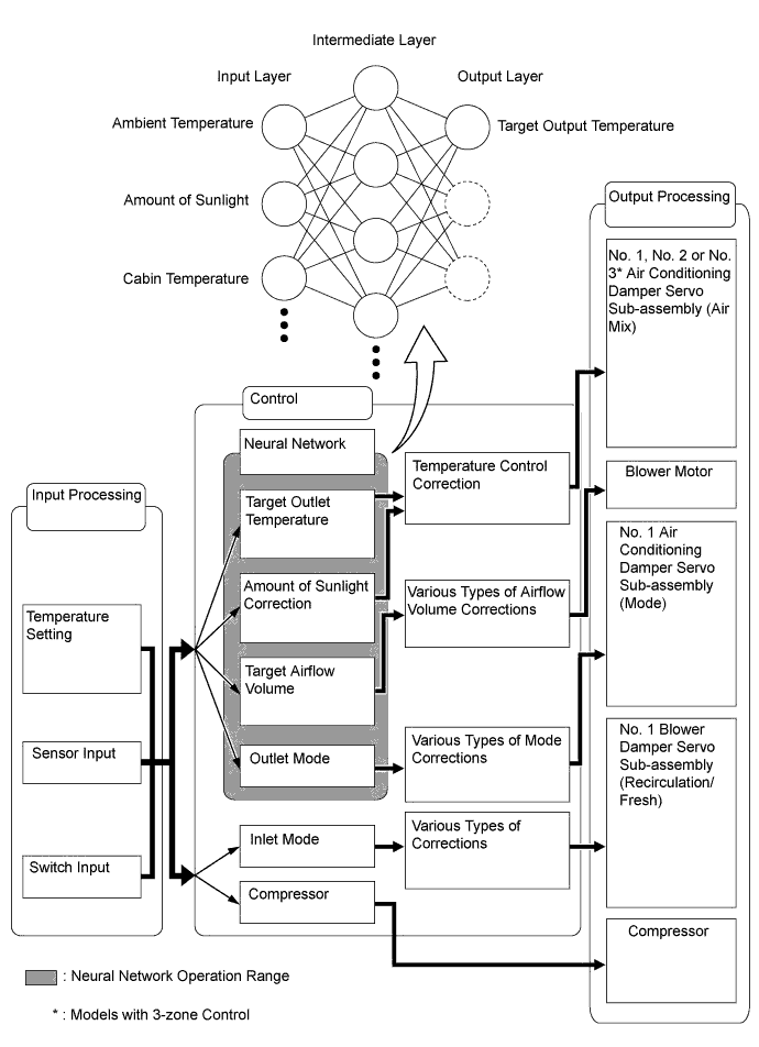
Previously, in automatic air conditioning systems without neural network control, the air conditioning amplifier assembly determined the required outlet air temperature and blower air volume in accordance with the calculation formula that has been obtained based on information received from the sensors. However, because the senses of a person are rather complex, a given temperature is sensed differently, depending on the environment in which the person is situated. For example, a given amount of solar radiation can feel comfortably warm in a cold climate, or extremely uncomfortable in a hot climate. Therefore, as a technique for performing a higher level of control, a neural network has been adopted in the automatic air conditioning system. With this technique, the data that has been collected under varying environmental conditions is stored in the air conditioning amplifier assembly. The air conditioning amplifier assembly can then perform control in a way that provides enhanced air conditioning comfort.
-
The neural network control consists of neurons in the input layer, intermediate layer and output layer. The input layer neurons process the input data of the outside temperature, the amount of sunlight, and the room temperature based on the outputs of the switches and sensors, and output them to the intermediate layer neurons. Based on this data, the intermediate layer neurons adjust the strength of the links among the neurons. The sum of these is then calculated by the output layer neurons in the form of the required outlet temperature, solar correction, target airflow volume and outlet mode control volume. Accordingly, the air conditioning amplifier assembly controls the servo motors and blower motor in accordance with the control volumes that have been calculated by the neural network control.
-
-
Automatic Recirculation Control
-
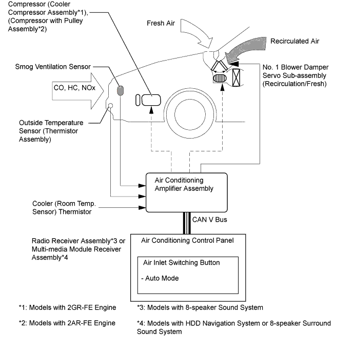
When the automatic recirculation control is operating, the air conditioning amplifier assembly automatically changes air inlet mode to fresh air or recirculate air mode based on signals from the smog ventilation sensor, outside temperature sensor (thermistor assembly), and cooler (room temp. sensor) thermistor when AUTO air inlet mode is selected.
-
The air conditioning amplifier assembly detects harmful elements (CO, HC and NOx) based on smog ventilation sensor signals and automatically switches air inlet mode to recirculate air mode to prevent such harmful elements from entering the cabin.
-
The air conditioning amplifier assembly detects room temperature based on a cooler (room temp. sensor) thermistor signal and automatically switches air inlet mode to recirculate air mode to prevent the room temperature from becoming too high.
-
The air conditioning amplifier assembly detects outside temperature based on a outside temperature sensor (thermistor assembly) signal and automatically switches air inlet mode to fresh air mode to prevent the windshield from fogging up.
-
-
-
Pollen Removal Mode Control
-
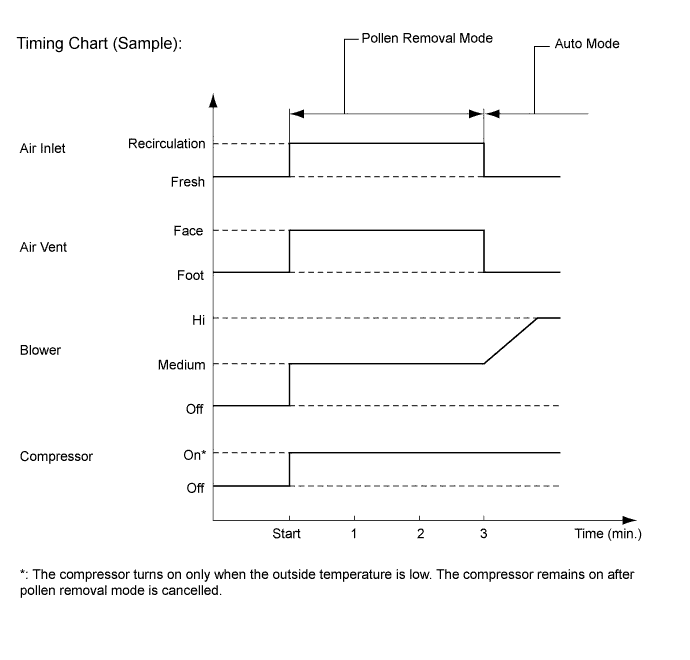
When the pollen removal switch is pressed, the pollen removal mode control is activated. Then, the air vent is switched to the FACE mode and recirculated pollen free air flows in the area around the upper part of the bodies of the driver and front passenger.
-
When the pollen removal switch signal is received by the air conditioning amplifier assembly, the air conditioning amplifier assembly controls the compressor, air inlet servo motor, air vent servo motor and blower motor as shown in the timing chart below.
-
This control usually operates for approximately 3 minutes. However, when the outside temperature is low, it will operate for approximately 1 minute.
-
After this control stops operating, the air conditioning amplifier assembly controls the air conditioning system using AUTO mode.
-
-
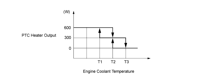
PTC Heater Control (Models with PTC Heater)
-
The output of the quick heater assembly is controlled by the air conditioning amplifier assembly in accordance with the engine coolant temperature, engine speed, air mix setting, and electrical load (generator assembly power ratio).
-
-
ECO Mode Control
-
During ECO mode control, the air conditioning amplifier assembly restricts the air conditioning system performance under specified conditions, thus improving fuel economy.
-
ECO mode control is activated when the drive mode select is selected to ECO mode, and then restricts the air conditioning system performance as described below.
Control Outline Inside/outside Air Switch Control Automatically switches the air inlet port to recirculation mode when the outside air temperature is equal to or higher than a predetermined temperature and reduces the power consumption. Blower Level Control Sets the blower level in AUTO mode lower than normal, and suppresses the power consumption. PTC Heater Control* Suppresses the power consumption. Heating Restriction Control Changes the air outlet temperature by entering ECO mode during heating and increases the amount of engine-off time when the drive mode is in ECO, thus improving fuel economy. Compressor Speed Restriction Control Restricts the maximum compressor speed during cooling and reduces the power consumption. *: Models with PTC heater
-
-
-
CONSTRUCTION
-
Air Conditioning Control Panel
-
A push-button type air conditioning control panel is integrated with a radio receiver assembly*1 or multi-media module receiver assembly*2.
*1: Models with 8-speaker sound system
*2: Models with HDD navigation system or 8-speaker surround sound system
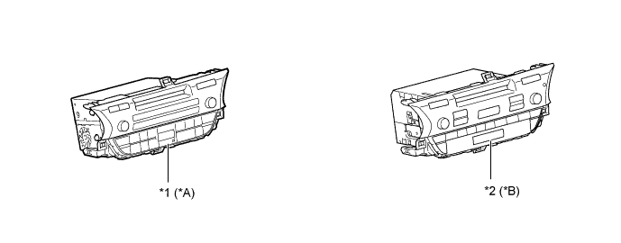
Text in Illustration *A Models with 8-speaker Sound System *B Models with HDD Navigation System or 8-speaker Surround Sound system *1 Radio Receiver Assembly *2 Multi-media Module Receiver Assembly
-
-
Accessory Meter Assembly (Models with 8-speaker Sound System)
-
The air conditioning status is displayed on the accessory meter assembly.
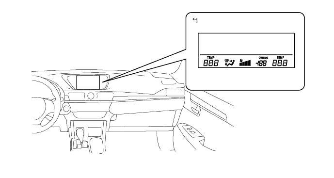
Text in Illustration *1 Accessory Meter Assembly - -
-
-
Multi-media Module Display (Models with HDD Navigation System or 8-speaker Surround Sound System)
-
The air conditioning status is displayed on the multi-media module display.
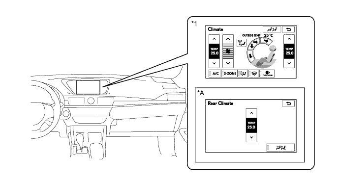
Text in Illustration *A Models with 3-zone control - - *1 Multi-media Module Receiver Assembly - -
-
-
Cooler Control Switch Assembly (Models with 3-zone Control)
-
A push-button type cooler control switch assembly is used for the rear seat.
-
-
Air Conditioning Radiator Assembly
-
The air conditioning radiator assembly consists of the evaporator, heater radiator unit sub-assembly, servo motors, evaporator temperature sensor (No. 1 cooler thermistor) and blower with fan motor sub-assembly.
-
A semi-center location air conditioning radiator assembly, in which the evaporator and heater radiator unit sub-assembly are placed in the vehicle's longitudinal direction. As a result, the air conditioning radiator assembly has been made compact and lightweight.
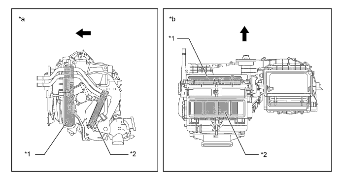
Text in Illustration *1 Evaporator *2 Heater Radiator Unit Sub-assembly *a Side View *b Top View 
Front - -
-
-
Evaporator
-
A Revolutionary super-Slim structure (RS) type evaporator is used.
-
Placing the tanks at the top and the bottom of the evaporator and adopting a micropore tube construction has provided the following benefits:
-
The heat exchanging efficiency has been improved.
-
The temperature distribution has been made more uniform.
-
The evaporator has been made thinner.
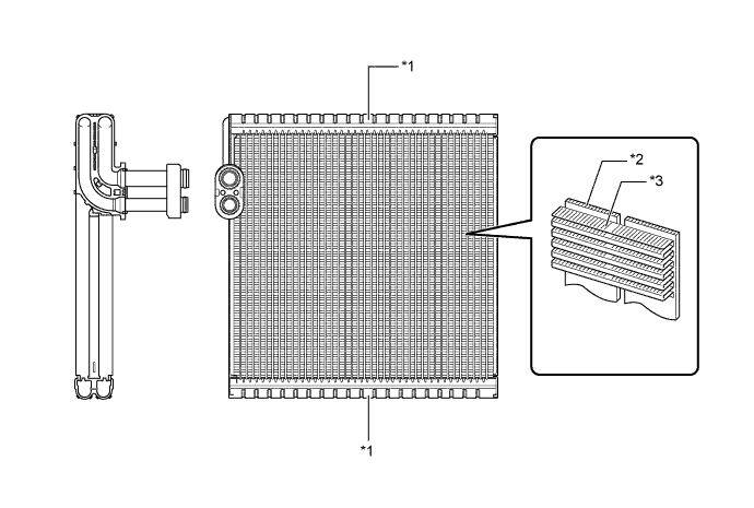
Text in Illustration *1 Tank *2 Micropore Tube *3 Cooling Fin - - -
-
-
Evaporator Temperature Sensor (No. 1 Cooler Thermistor)
-
The evaporator temperature sensor (No. 1 cooler thermistor) detects the temperature of the cooled air immediately after the evaporator in the form of resistance changes, and outputs this data to the air conditioning amplifier assembly.
-
-
Heater Radiator Unit Sub-assembly
-
The compact, lightweight and highly efficient Straight Flow Aluminum (SFA)-II type heater radiator unit sub-assembly is used for the air conditioning system.
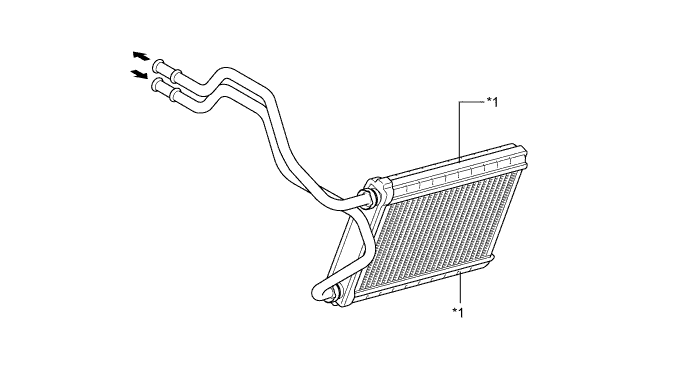
Text in Illustration *1 Tank - -
-
-
Quick Heater Assembly (Models with PTC Heater)
-
The quick heater assembly consists of a PTC element, an aluminum fin, and a brass plate. When current is applied to the PTC element, it generates heat to warm the air that passes through the unit.
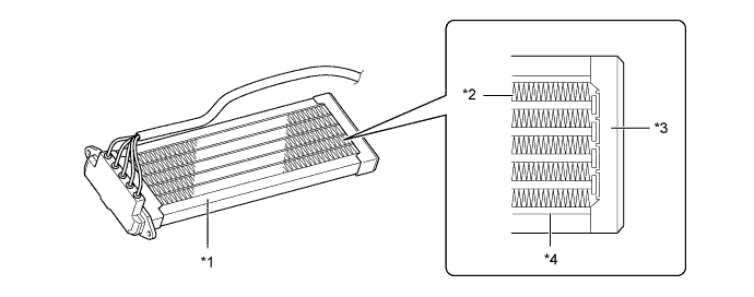
Text in Illustration *1 PTC Heater *2 Aluminum Fin *3 Brass Plate *4 PTC Element
-
-
Blower with Fan Motor Sub-assembly
-
The blower with fan motor sub-assembly has a built-in blower controller which is controlled by the air conditioning amplifier assembly.
-
-
Air Conditioning Harness Assembly
-
An air conditioning harness assembly is used in the wire harness connection that connects the servo motor from the air conditioning amplifier assembly.
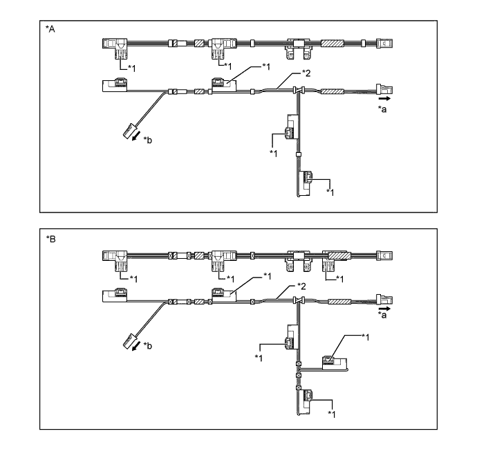
Text in Illustration (LHD Models:) *A Models without 3-zone Control *B Models with 3-zone Control *1 Bus Connector *2 Air Conditioning Harness Assembly *a To Air Conditioning Amplifier Assembly *b To Evaporator Temperature Sensor (No. 1 Cooler Thermistor) 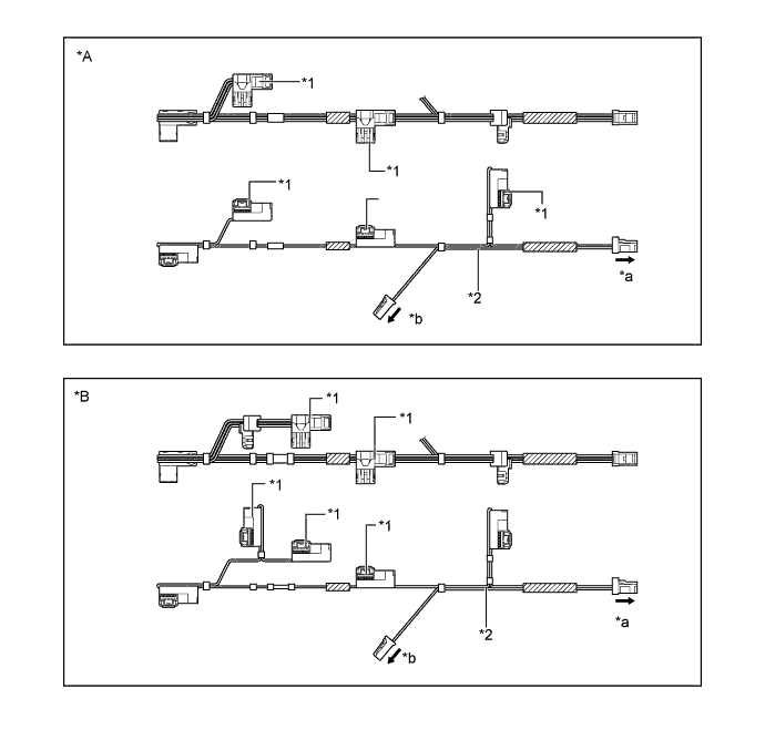
Text in Illustration (RHD Models:) *A Models without 3-zone Control *B Models with 3-zone Control *1 Bus Connector *2 Air Conditioning Harness Assembly *a To Air Conditioning Amplifier Assembly *b To Evaporator Temperature Sensor (No. 1 Cooler Thermistor) -
The air conditioning harness assembly has a built-in driver IC with a position detection function that communicates with each servo motor connector and actuates the servo motor. This enables bus communication for the servo motor wire harness with a more lightweight construction and a reduced number of wires.
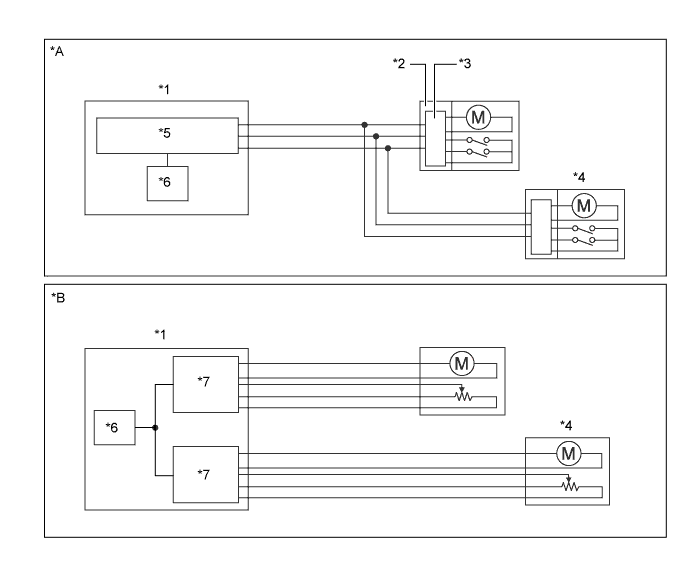
Text in Illustration *A Models with Bus Connector *B Models without Bus Connector *1 Air Conditioning Amplifier Assembly *2 Bus Connector *3 Communication Driver IC *4 Servo Motor *5 Communication IC *6 CPU *7 Driver IC - -
-
-
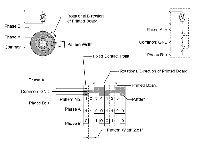
Servo Motor
-
The pulse pattern type servo motor consists of a printed-circuit board and a servo motor. The printed-circuit board has 3 contact points, and can transmit 2 on-off signals to the air conditioning amplifier assembly based on the difference in the pulse phases. The bus connector can detect damper position and direction of movement with this signal.
-
-
Clean Air Filter
-
A pollen removal type filter is used. This filter is made of polyester and excels in the removal of dust and pollen. Because the filter is made of polyester it can be disposed of easily as a non-hazardous combustible material, a feature provided out of consideration for the environment.
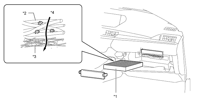
Text in Illustration *1 Clean Air Filter *2 Large Foreign Object Filter Layer *3 Electret Layer *4 Air Flow
-
-
Cooler Condenser Assembly
-
The cooler condenser assembly consists of 2 cooling portions: a condensing portion and a super-cooling portion. These portions are integrated with a gas-liquid separator (modulator). This cooler condenser assembly uses a sub-cool cycle that offers excellent heat-exchange performance.
-
In the sub-cool cycle, after the refrigerant passes through the condensing portion of the condenser, both the liquid refrigerant and the gaseous refrigerant that could not be liquefied are cooled again in the super-cooling portion. Thus, the refrigerant is sent to the evaporator in an almost completely liquefied state.
-
The desiccant and filter at the bottom of the modulator remove moisture and debris from the refrigerant.
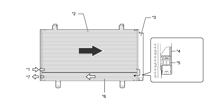
Text in Illustration *1 Gaseous Refrigerant *2 Condensing Portion *3 Modulator *4 Desiccant *5 Filter *6 Super-cooling Portion *7 Liquid Refrigerant - - Tech Tips
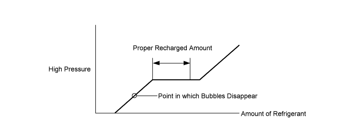
The point at which the air bubbles disappear in the refrigerant of the sub-cool cycle is lower than the proper amount of refrigerant with which the system must be filled. Therefore, if the system is recharged with refrigerant based on the point at which the air bubbles disappear, the amount of refrigerant would be insufficient. As a result, the cooling performance of the system would be affected. Overcharging the system with refrigerant will also lead to reduced performance. For the proper method of verifying the amount of refrigerant and for instructions on how to recharge the system with refrigerant, refer to the Repair Manual.
-
-
Compressor
-
The compressor is a continuously variable capacity type air conditioning compressor. Its capacity can be varied in accordance with the cooling load of the air conditioning system.
-
The compressor consists of a pulley, shaft, lug plate, swash plate, piston, shoe, crank chamber, cylinder, air conditioning lock sensor (2GR-FE engine), solenoid valve with built-in Crank chamber to Suction passage (CS) valve, air conditioning mass flow sensor, oil separator and variable suction side throttle.
-
The oil separator consists of an oil separator chamber and an oil separator cylinder.
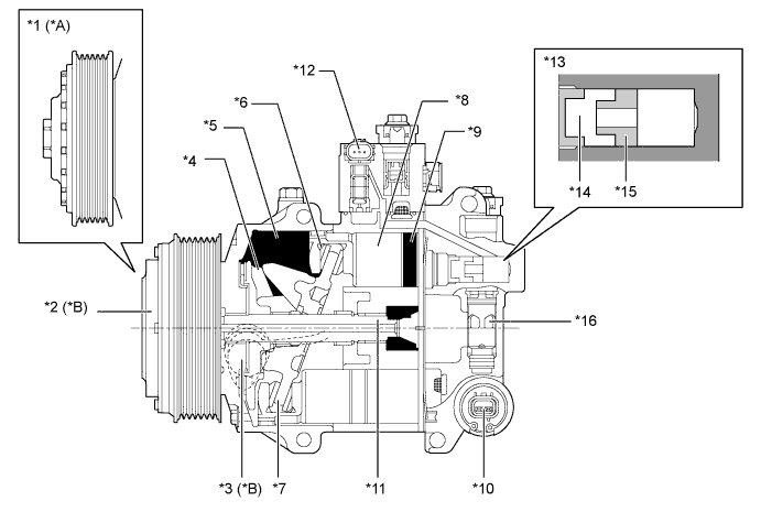
Text in Illustration *A Models with 2AR-FE Engine *B Models with 2GR-FE Engine *1 Pulley *2 Magnetic Clutch Assembly *3 Air Conditioning Lock Sensor *4 Lug Plate *5 Crank Chamber *6 Shoe *7 Swash Plate *8 Piston *9 Cylinder *10 Solenoid Valve with Built-in CS Valve *11 Shaft *12 Air Conditioning Mass Flow Sensor *13 Oil Separator *14 Oil Separator Chamber *15 Oil Separator Cylinder *16 Variable Suction Side Throttle -
A plastic Damper and Limiter (DL) pulley and a steel pulley with magnetic clutch are present.
-
The plastic DL pulley contains a damper mechanism to absorb the torque fluctuations of the engine and a limiter mechanism to protect the drive belt in case the compressor locks. If the compressor locks, the limiter integrated into the pulley breaks, disconnecting the pulley from the compressor. To reduce weight, the pulley portion is made of plastic.
-
If the compressor locks, the steel with magnetic clutch pulley turns the magnetic clutch off to protect the drive belt and separates the pulley from the compressor.
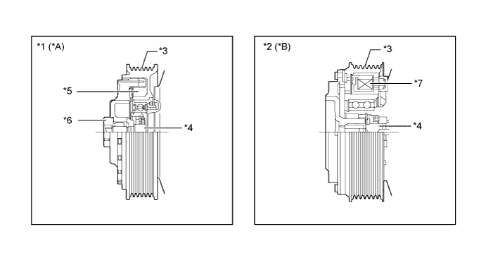
Text in Illustration *A Models with 2AR-FE Engine *B Models with 2GR-FE Engine *1 Plastic DL Pulley *2 Steel with Magnetic Clutch Pulley *3 Pulley Portion *4 Shaft *5 Damper *6 Limiter *7 Magnetic Clutch - -
-
-
Cooler (Room Temp. Sensor) Thermistor
-
The cooler (room temp. sensor) thermistor detects the room temperature based on changes in the resistance of its built-in thermistor. This signal is used by the air conditioning amplifier assembly.
-
-
Outside Temperature Sensor (Thermistor Assembly)
-
The outside temperature sensor (thermistor assembly) detects the outside temperature based on changes in the resistance of its built-in thermistor. This signal is used by the air conditioning amplifier assembly.
-
-
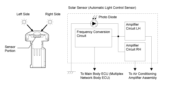
Solar Sensor (Automatic Light Control Sensor)
-
The solar sensor (automatic light control sensor) consists of a photo diode, 2 amplifier circuits and a frequency conversion circuit.
-
The solar sensor (automatic light control sensor) detects (in the form of changes in the current that flows through the built-in photo diode) the changes in the amount of sunlight from its left and right sides (2 directions) and outputs these sunlight strength signals to the air conditioning amplifier assembly for the automatic air conditioning control.
-
-
Smog Ventilation Sensor
-
The smog ventilation sensor detects harmful elements such as CO, HC, and NOx, which are present in the air outside of the vehicle. The sensor outputs it to the air conditioning amplifier assembly.
-
-
No. 1 Ion Generator Sub-assembly
-
The No. 1 ion generator sub-assembly is controlled by the air conditioning assembly and operates in accordance with the blower with fan motor sub-assembly.
-
The No. 1 ion generator sub-assembly emits "nanoe" ions that are electrically charged and encapsulated with water. The ions are discharged into the cabin through the driver side vent to provide skin-friendly clean air.*
*: According to temperature and humidity conditions, fan speed and air outlet mode selected, the No. 1 ion generator sub-assembly may not operate at full capacity.
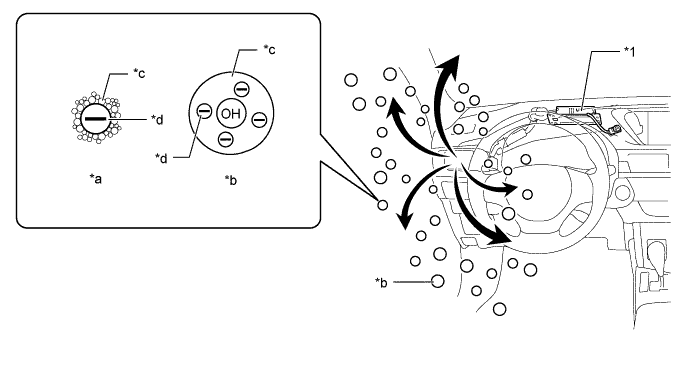
Text in Illustration *1 No. 1 Ion Generator Sub-assembly - - *a Common Negative Ion *b "nanoe" *c H2O
*d Electron CAUTION:
Do not attempt to disassemble or repair the No. 1 ion generator sub-assembly because it contains high voltage parts.
Note
Do not insert anything into the driver side vent, attach anything to it, or use sprays around the driver side vent. These things may cause the No. 1 ion generator sub-assembly not to work properly.
Tech Tips
-
When the No. 1 ion generator sub-assembly operates, a small amount of ozone is emitted and may be faintly smelled in some situations. However, this is approximately the same as the amount that already exists in nature, such as in forests, and as such has no effect on the human body.
-
A slight noise may be heard during operation.
-
This does not indicate a malfunction.
-
"nanoe" is a trademark of Panasonic Corporation.
-
-
-
-
OPERATION
-
Mode Position and Door Operation
-
Air Conditioning Unit
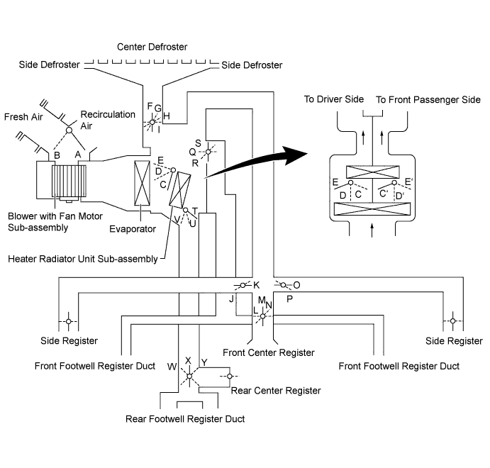
Control Damper Operation Position Door Position Operation Air Inlet Control Damper FRESH A Allows fresh air to enter. RECIRCULATION B Causes internal air to recirculate. Air Mix Control Damper MAX COLD to MAX HOT Temperature Setting C - D - E
(C' - D' - E')
T - U - V
Varies the mixture ratio of the warm air and the cool air in order to regulate the temperature continuously between hot and cold. Mode Control Damper 
FACE I, K, M, O, S, W Air blows out of the front and rear center registers, and side registers. 
BI-LEVEL I, K, N, O, R, X Air blows out of the front and rear center registers, side register and front and rear footwell registers ducts. 
FOOT H, J, L, P, Q, X Air blows out of the front and rear footwell register duct, and side registers. In addition, air blows out slightly from the center defroster and side defrosters. 
FOOT/DEF G, J, L, P, Q, X Defrosts the windshield through the center defroster, side defrosters, side registers, and rear center register, while air is also blown out from the front and rear footwell register ducts. 
DEF F, J, L, P, S, Y Defrosts the windshield through the center defroster, side defroster, and side registers.
-
-
Air Outlets and Airflow Volume
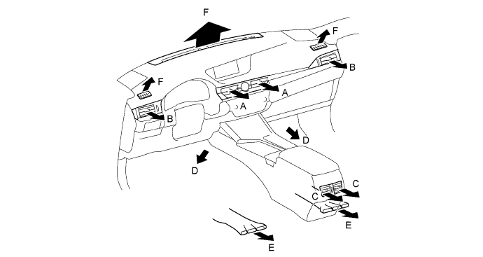
MODE Selection Register Footwell Defroster AUTO Manual CTR SIDE RR FR RR A B C D E F FACE


BI-LEVEL


FOOT-F*1

FOOT-R*2
FOOT-D*3
FOOT/DEF
DEF

-
*1: Regular foot mode
-
*2: Foot mode with large airflow volume from footwell rear ducts
-
*3: Foot mode with large airflow volume from defrosters
-
The size of each circle ○ indicates the ratio of airflow volume.
-
-
Compressor Operation
-
Variable Capacity Operation
-
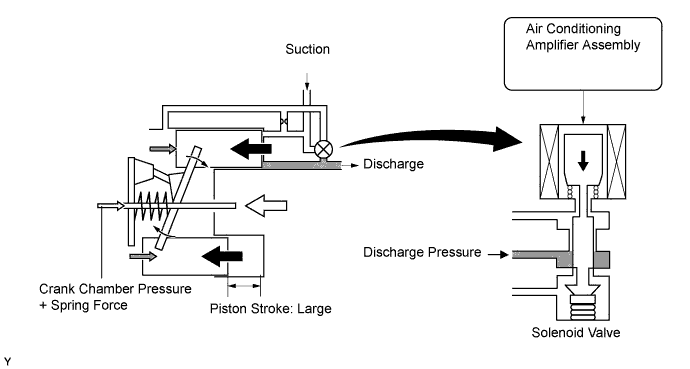
A solenoid valve is connected to the suction passage, the discharge passage and the crank chamber passage.
-
The solenoid valve operates under duty cycle control in accordance with the signals from the air conditioning amplifier assembly.

-
When the solenoid valve closes (solenoid coil is energized), a difference in pressure is created and the pressure in the crank chamber decreases. Then, the pressure that is applied to the right side of the piston becomes greater than the pressure that is applied to the left side of the piston. This compresses the spring and tilts the lug plate. As a result, the piston stroke and discharge capacity increases.
-
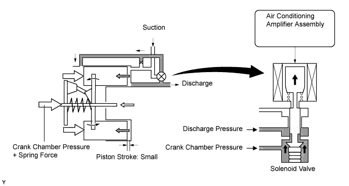
When the solenoid valve opens (solenoid coil is not energized), the difference in pressure disappears. Then, the pressure that is applied to the left side of the piston becomes the same as the pressure that is applied to the right side of the piston. Thus, the spring elongates and eliminates the tilt of the lug plate. As a result, the piston stroke becomes small, decreasing the discharge capacity.
-
-
Air Conditioning Lock Sensor Operation (Models with 2GR-FE Engine)
-
The air conditioning lock sensor outputs a pulley rotation signal to the air conditioning amplifier assembly.
-
The air conditioning amplifier assembly compares this signal with the engine speed signal sent from the ECM to judge if the compressor is locked. If the compressor is locked, the magnetic clutch is turned off.
-
-
Air Conditioning Mass Flow Sensor Operation
-
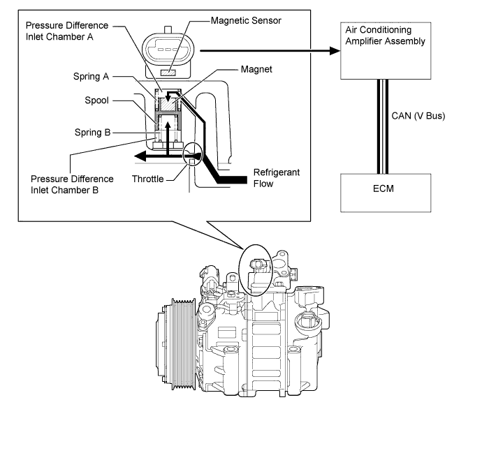
Using a spool that changes its position according to the amount of refrigerant flow, the air conditioning mass flow sensor detects the amount of refrigerant flow.
-
The air conditioning mass flow sensor outputs a voltage by converting the change of magnetic flux that occurs due to the magnet that is installed on the spool.
-
The spool changes its position according to the pressure difference between the pressure before and after the refrigerant flow throttle.
-
If the amount of refrigerant flow is small, the pressure difference between pressure difference inlet chamber A and B is low, allowing the force of spring B to push up the spool.
-
If the amount of refrigerant flow is large, the pressure difference between pressure difference inlet chamber A and B is high. The pressure difference overwhelms the force of spring B, and the spool moves down.
-
Based on the amount of refrigerant flow detected by the air conditioning mass flow sensor, the air conditioning amplifier assembly and ECM cooperatively control the cooler compressor assembly and the engine.
-
-
Oil Separator Operation
-
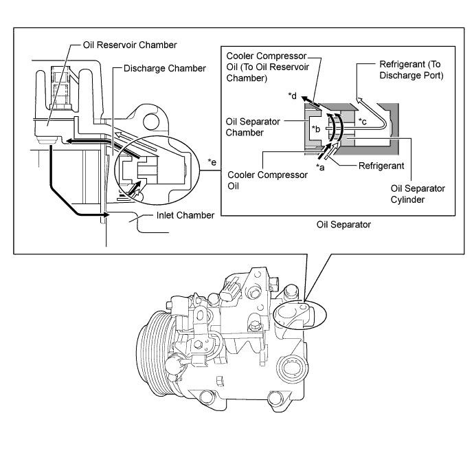
A mixture of refrigerant and cooler compressor oil flows into the oil separator chamber from the discharge chamber (*a).
-
The force of the refrigerant and oil mixture flow turns the oil separator cylinder, allowing the oil and refrigerant to be centrifugally separated (*b).
-
The separated refrigerant flows to the cooler condenser assembly through the discharge port (*c).
-
The separated oil circulates and lubricates the inside of the compressor by flowing through the oil reservoir chamber, inlet chamber, cylinder and discharge chamber. In addition, the amount of oil that is discharged by the compressor is suppressed (*d).
-
The oil separator is installed in the refrigerant passage to separate cooler compressor oil from the refrigerant that is discharged. This helps to prevent the cooler compressor oil from flowing into the air conditioning system and reducing cooling effectiveness (*e).
-
-
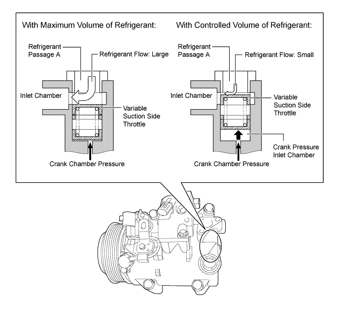
Variable Suction Side Throttle Operation
-
Refrigerant inlet pressure is applied to the top of the variable suction side throttle and crank chamber pressure to the bottom of the variable suction side throttle.
-
The pressure difference moves the variable suction side throttle up and down, expanding and contracting the refrigerant inlet passage.
-
When the refrigerant flow is at a maximum, the refrigerant inlet pressure is greater than the crank chamber pressure. This causes the variable suction side throttle to move down, fully opening the refrigerant inlet passage and lowering the refrigerant inlet resistance.
-
When the amount of refrigerant flow is controlled, the crank chamber pressure is greater than the refrigerant inlet pressure, raising the variable inlet throttle to contract the flow passage.
-
These controls suppress noise by reducing pulsation from the refrigerant inlet.
-
-
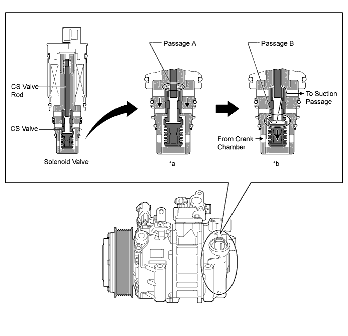
CS Valve Operation
-
The Crank chamber to Suction passage (CS) valve, built into the solenoid valve, operates in accordance with the suction pressure. The CS valve consists of passage A and passage B.
-
If the vehicle is left parked for a long period, refrigerant may accumulate in the crank chamber due to the heat capacity difference.
-
The solenoid valve is controlled by the air conditioning amplifier assembly. While the cooler compressor assembly is operating, the solenoid valve pushes down the CS valve rod and open passage A (*a).
-
Under the above condition, only if the refrigerant accumulates in the crank chamber, the crank chamber pressure will become high. As a result, the bellows will contract because of the pressure difference with its internal pressure (vacuum), and opens passage B (*b).
-
This causes the accumulated refrigerant to be drawn in via passage A and B, clearing the accumulated refrigerant earlier and ensuring a more immediate cooling effect.
-
-
-
-
DIAGNOSIS
-
The air conditioning amplifier assembly has a diagnosis function. It stores a record of any air conditioning system failures in its memory in the form of Diagnostic Trouble Codes (DTCs). For details, refer to the Repair Manual.
-