STEERING COLUMN SYSTEM DETAILS
-
FUNCTION OF MAIN COMPONENTS
-
Power Tilt and Telescopic System
Component Function Electric Power Steering Column Sub-assembly Tilt Motor Tilts the steering column up and down. Telescopic Motor Contracts and extends (telescopes) the steering column. Tilt and Telescopic Switch Sends signals to the multiplex tilt and telescopic ECU based on the driver's operation of the tilt and telescopic switch. Multiplex Tilt and Telescopic ECU
-
Controls the tilt and telescopic motors based on the following information.
-
The position of the tilt and telescopic motors, and the operation of the tilt and telescopic switch.
-
In addition, it controls the tilt motor and telescopic motor based on the command of the main body ECU (multiplex network body ECU).
Main Body ECU (Multiplex Network Body ECU) Sends an auto away or auto return command to the multiplex tilt and telescopic ECU. -
-
-
SYSTEM CONTROL
-
The power tilt and telescopic system has the following control functions, thus providing excellent ease of operation and entry/exit.
Function Outline Manual Control The tilt and telescopic positions can be adjusted using the tilt and telescopic switch. Automatic Control Auto Away When the power source is changed from on (ACC) or on (IG) to off, the steering wheel automatically tilts up and fully retracts. Auto Return When the power source is changed from off to on (ACC) or on (IG), the steering wheel automatically returns to the previous position which was set before the power source was turned off. Memory Control The memory system can store the driver seat position and tilt and telescopic position, and outer mirror positions. Up to 2 memory positions can be stored in the system memory and recalled. 2 positions can be saved for the main body ECU (multiplex network body ECU).
-
-
CONSTRUCTION
-
Tilt and Telescopic Mechanism (Models with Manual Tilt and Telescopic Mechanism)
-
The tilt and telescopic mechanism consists mainly of the tilt and telescopic lever, column tube, cam, column tube bracket, breakaway bracket, and tilt and telescopic steering stopper.
-
When the tilt and telescopic mechanism is in its locked state, the tilt and telescopic lever at the locked position causes the tilt and telescopic steering stopper to tighten the cam and column tube bracket. This secures the column tube, so movement in the tilt direction and in the telescopic direction is locked.
-
When the tilt and telescopic mechanism is in its unlocked state, the tilt and telescopic lever at the unlocked position causes the tilt and telescopic steering stopper to loosen the cam and column tube bracket. This frees the column tube to move in the tilt direction and in the telescopic direction, enabling adjustment.
-
A stepless adjustment enables the tilt mechanism to be tilted 40 mm (1.57 in.) vertically, and the telescopic mechanism to be moved 40 mm (1.57 in.) longitudinally.
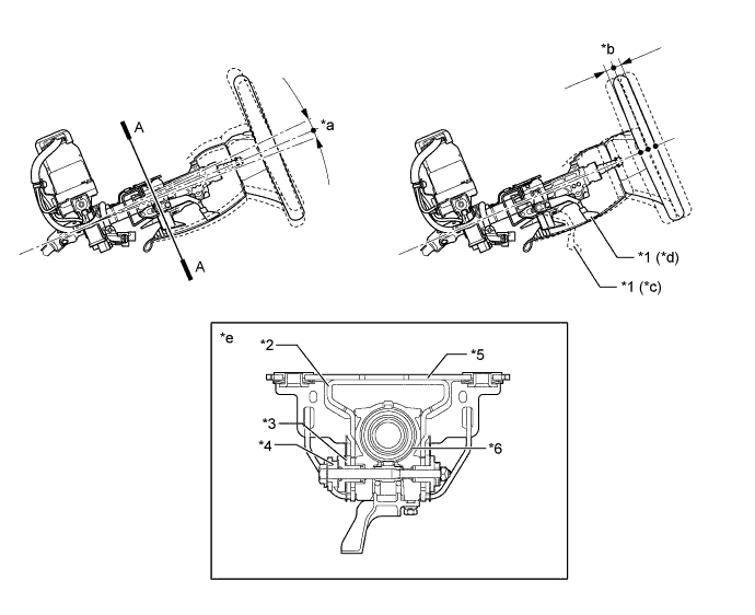
Text in Illustration *1 Tilt and Telescopic Lever *2 Column Tube Bracket *3 Column Tube Attachment *4 Tilt and Telescopic Steering Stopper *5 Breakaway Bracket *6 Column Tube *a Tilt *b Telescopic *c Unlocked Position *d Locked Position *e A-A Cross Section - -
-
-
Tilt and Telescopic Mechanism (Models with Power Tilt and Telescopic System)
-
A stepless adjustment enables the tilt mechanism to be tilted 59.0 mm (2.32 in.) vertically, and the telescopic mechanism to be moved 45 mm (1.77 in.) longitudinally.
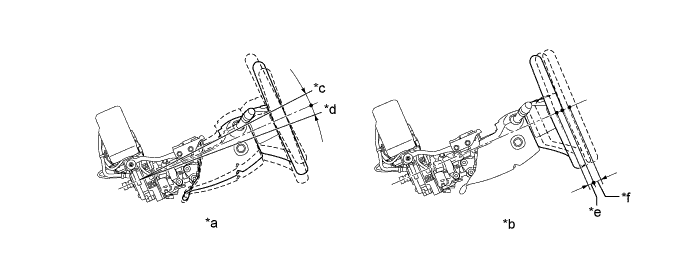
Text in Illustration *a Tilt *b Telescopic *c 28.4 mm (1.12 in.) *d 30.6 mm (1.20 in.) *e 20 mm (0.79 in.) *f 25 mm (0.98 in.)
-
-
Energy Absorbing Mechanism (Models with Manual Tilt and Telescopic Mechanism)
-
The energy absorbing mechanism in the steering column assembly consists of a main shaft column tube and steering intermediate shaft.
-
The steering column assembly is mounted on the instrument panel reinforcement. The steering column assembly and the steering gear assembly are connected with a contractile steering intermediate shaft.
-
When the steering gear assembly moves during a collision (primary collision), the steering intermediate shaft contracts, thus helping reduce the possibility of the steering column assembly and the steering wheel assembly protruding into the cabin.
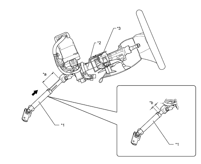
Text in Illustration (Primary Collision:) *1 Steering Intermediate Shaft *2 Steering Column Assembly *3 Breakaway Bracket - - *a Before Primary Collision *b After Primary Collision 
Contract - - -
When a collision impact is transmitted to the steering wheel (secondary collision), the steering wheel and the driver's airbag help absorb the impact. In addition, the breakaway bracket separates, and the column tube contracts. At this time, the friction resistance of the sliding portion absorbs the energy. This sequential energy absorbing mechanism helps absorb the impact of the secondary collision.
Text in Illustration (Secondary Collision:) *1 Capsule (Plastic) *2 Breakaway Bracket *3 Column Tube *4 Inner Tube *a Before Secondary Collision *b After Secondary Collision Secondary Collision - -
-
-
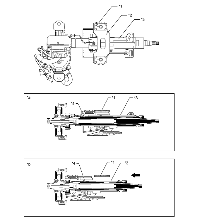
Energy Absorbing Mechanism (Models with Power Tilt and Telescopic System)
-
The energy absorbing mechanism in the steering column assembly consists of main shaft column tube and steering intermediate shaft assembly.
-
When the steering gear assembly moves during a collision (primary collision), the steering intermediate shaft assembly contracts, thus helping reduce the possibility of the steering column assembly and the steering wheel protruding into the cabin.
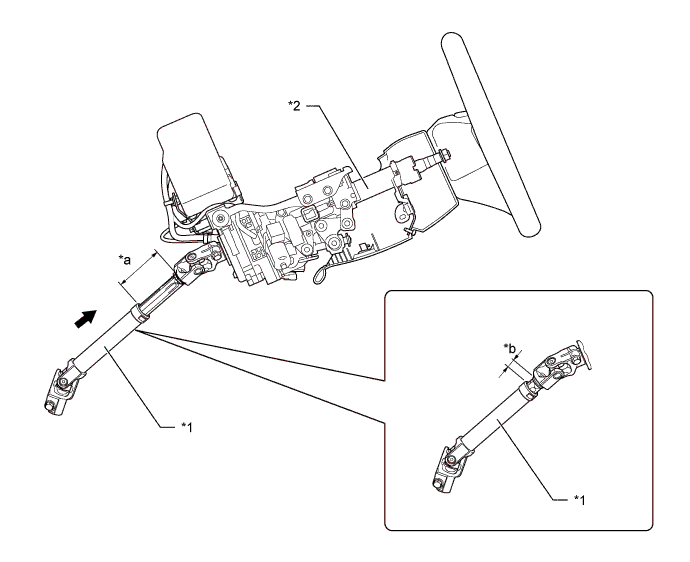
Text in Illustration (Primary Collision:) *1 Steering Intermediate Shaft *2 Steering Column Assembly *a Before Primary Collision *b After Primary Collision Contract - - -
When a collision impact is transmitted to the steering wheel (secondary collision), the steering wheel and the driver's airbag help absorb the impact. At this time, the frictional resistance of the contracting portion, attached to the column tube absorbs the energy. This sequential energy absorbing mechanism helps absorb the impact of a secondary collision.
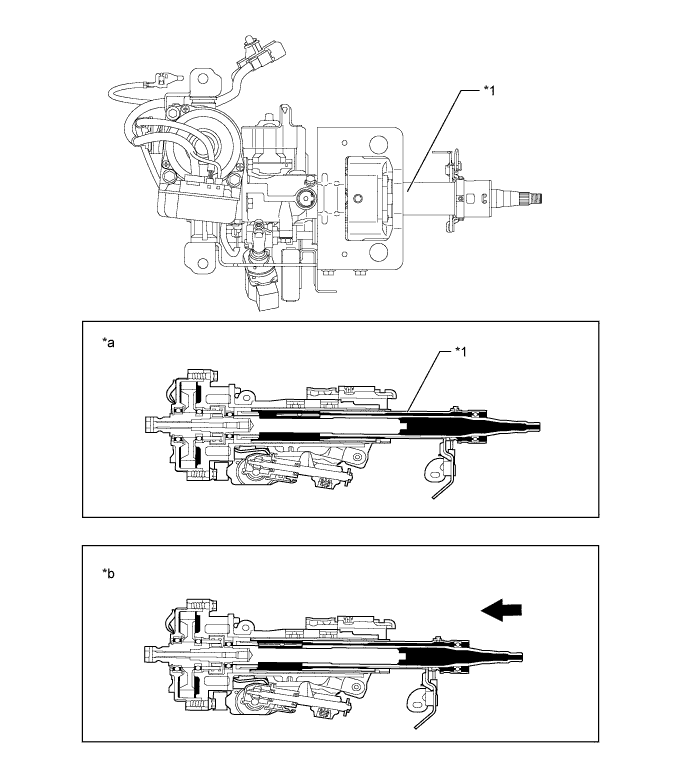
Text in Illustration (Secondary Collision:) *1 Column Tube - - *a Before Secondary Collision *b After Secondary Collision Secondary Collision - -
-
-
Steering Wheel Assembly
-
The steering shake damper is mounted to the steering wheel via a piece of rubber. This rubber mounting of the damper makes it possible for the vibration of the damper to cancel the vibration of the steering wheel assembly, thus improving driving comfort.
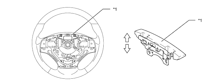
Text in Illustration *1 Steering Shake Damper - - 
Vibration Direction - -
-
-
-
FAIL-SAFE
-
When the multiplex tilt and telescopic ECU detects a malfunction in the power tilt and telescopic system, the ECU changes to a fail-safe mode. For details, refer to the Repair Manual.
-
-
DIAGNOSIS
-
If the multiplex tilt and telescopic ECU detects a malfunction in the power tilt and telescopic system, the ECU stores the malfunction data in memory. Then, by connecting the Global TechStream (GTS) to the DLC3, the Diagnostic Trouble Codes (DTCs) can be accessed and an active test can be performed to test the operation of the tilt motor and the telescopic motor. For details, refer to the Repair Manual.
-