BRAKE CONTROL SYSTEM DETAILS
-
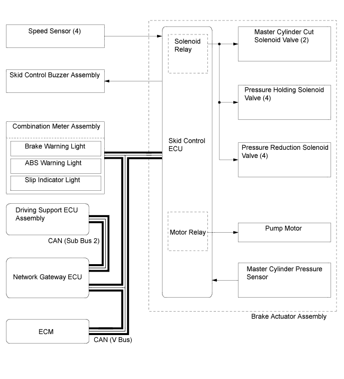
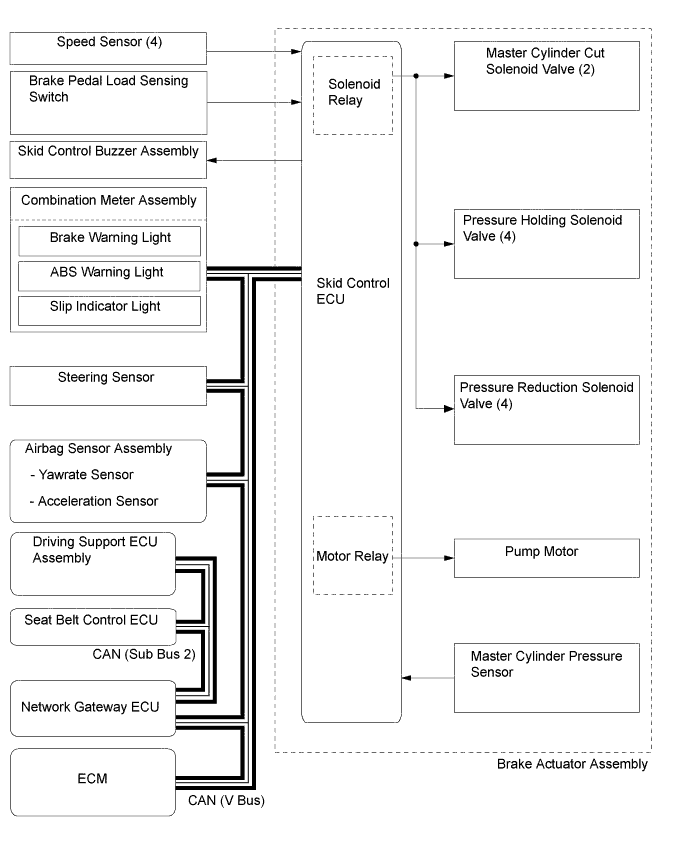
FUNCTION OF MAIN COMPONENTS
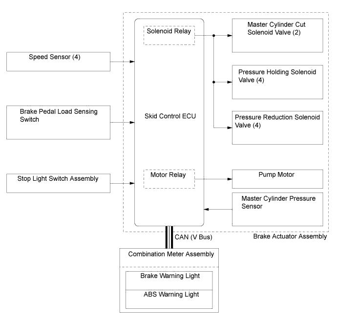
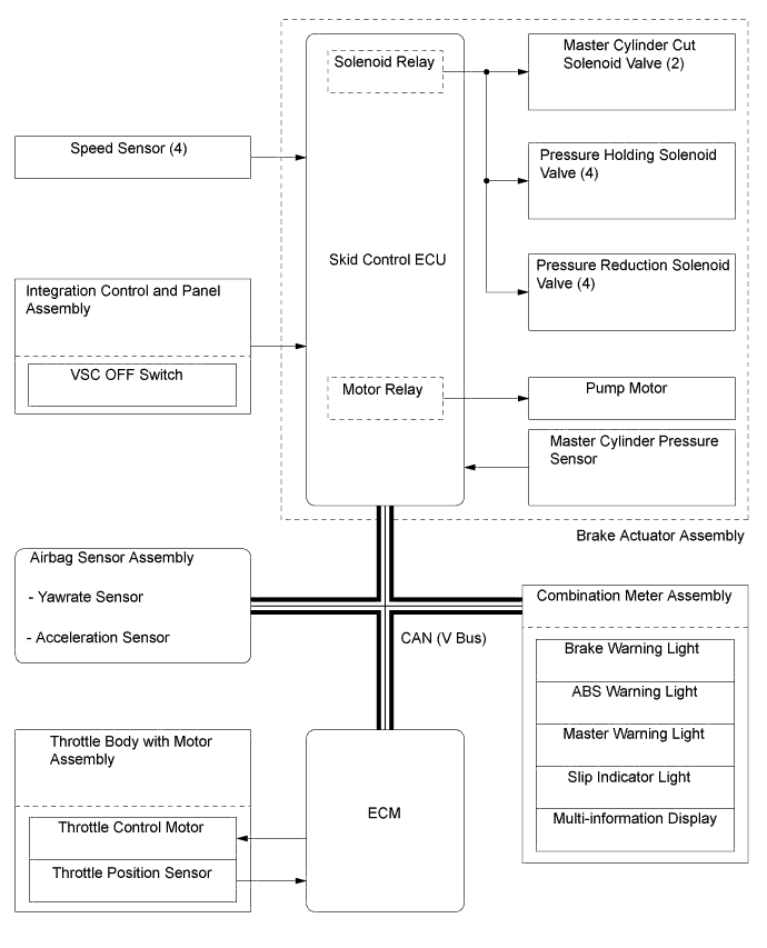
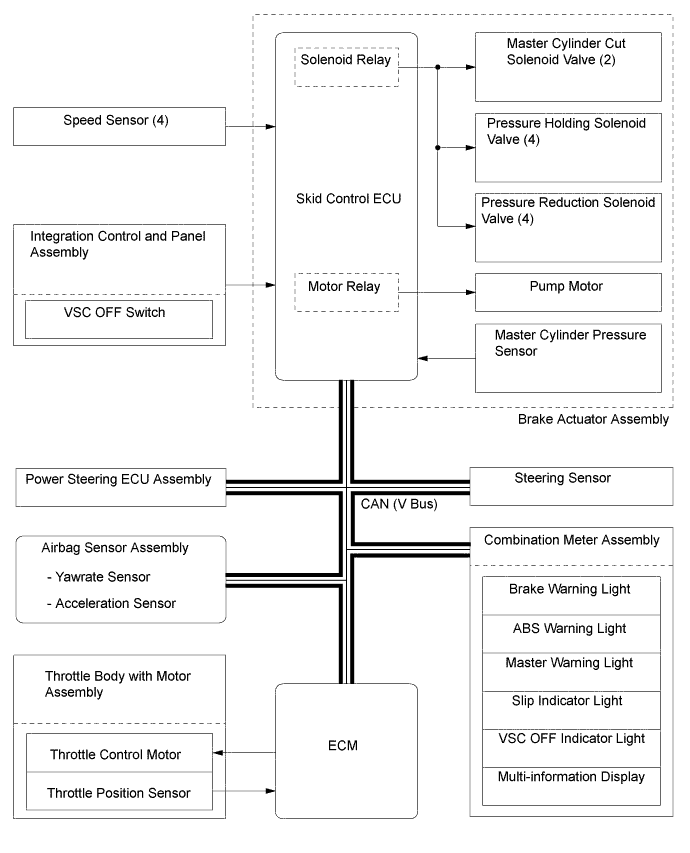
Component Function Brake Actuator Assembly Skid Control ECU Judges the vehicle driving condition based on the signals from each sensor and switch, and sends the brake control signals to the brake actuator. Solenoid Relay (Built into Skid Control ECU) Supplies power to the solenoid valves. Motor Relay (Built into Skid Control ECU) Supplies power to the pump motor. Solenoid Valves
-
The hydraulic circuit has 2 master cylinder cut solenoid valves, 4 pressure holding solenoid valves and 4 pressure reduction solenoid valves.
-
Change the fluid path based on the signals from the skid control ECU during the operation of the brake control system functions, in order to control the fluid pressure applied to the wheel cylinders.
Pump Motor Drives the pumps inside the brake actuator assembly. Master Cylinder Pressure Sensor Detects the master cylinder pressure. Speed Sensors Detect the wheel speed of each of the 4 wheels. Airbag Sensor Assembly
-
The airbag sensor assembly incorporates the acceleration sensor and yawrate sensor.
-
The yawrate sensor detects the vehicle's yaw rate.
-
The acceleration sensor detects the vehicle's longitudinal and lateral acceleration.
-
The airbag sensor assembly sends the detection signals from the yawrate sensor and acceleration sensor to the skid control ECU via CAN communication.
Steering Sensor Detects the steering direction and angle of the steering wheel. Stop Light Switch Assembly Detects the brake pedal depressing signal. Brake Pedal Load Sensing Switch Detects the brake pedal depression. Parking Brake Switch Assembly Detects the parking brake pedal status. Integration Control and Panel Assembly VSC OFF Switch Enables the driver to select Normal mode, TRC OFF mode, or VSC OFF mode. Skid Control Buzzer Assembly*1, *2 Emits a warning sound to inform the driver during brake control operation (operating dynamic radar cruise control or pre-crash brake). Main Body ECU (Multiplex Network Body ECU) Transmits the parking brake switch signal to the skid control ECU. Power Steering ECU Assembly Operates cooperatively with the skid control ECU to control the steering assist torque. ECM
-
Sends the throttle position signal, accelerator pedal position signal, engine speed signal etc., to the skid control ECU.
-
Based on the signals from the skid control ECU, controls the engine output.
Driving Support ECU Assembly*1, *2 Transmits a signal to the skid control ECU, in order to activate brake control when the ECU has determined that the distance to the preceding vehicle has been shortened based on signals from the millimeter wave radar sensor assembly. Seat Belt Control ECU*1 Receives a seat belt operation request signal from the driving support ECU assembly or skid control ECU and operates the seat belts. Combination Meter Assembly Brake Warning Light
-
Illuminates to alert the driver when the skid control ECU detects a malfunction in the EBD or brake system.
-
Illuminates to alert the driver when the brake fluid level is low.
-
Illuminates to inform the driver when the parking brake is operated.
ABS Warning Light Illuminates to alert the driver when the skid control ECU detects a malfunction in the ABS. Slip Indicator Light
-
Blinks to inform the driver when the TRC or VSC is performing control.
-
Illuminates to alert the driver when the skid control ECU detects a malfunction in the TRC and/or VSC.
VSC OFF Indicator Light Illuminates to inform the driver when VSC OFF mode is selected. Master Warning Light Illuminates to alert the driver when a message is being displayed on the multi-information display. Multi-information Display Displays a warning message to alert the driver , such as when TRC OFF mode is selected or when the vehicle is being driven with the parking brake still engaged. Buzzer Sounds to alert the driver when the vehicle is being driven with the parking brake still engaged. Radio Receiver Assembly*3 Hazard Warning Signal Switch Transmits a hazard warning light on/off request signal to the skid control ECU. Multi-media Module Receiver Assembly*4 *1: Models with pre-crash safety system
*2: Models with dynamic radar cruise control system
*3: Models with 8-speaker Sound System
*4: Models with HDD Navigation System
-
-
OPERATING CONDITION
-
Emergency Brake Signal
-
Emergency brake signal operating conditions are as shown in the following table.
Activating Conditions When all of the following conditions are met, the emergency brake signal starts operating:
-
Vehicle speed is over 55 km/h (35 mph).
-
Driver is depressing the brake pedal.
-
Emergency braking is detected from the vehicle deceleration.
Deactivating Conditions When any of the following conditions is met, the emergency brake signal stops operating:
-
Driver has released the brake pedal.
-
Emergency braking is no longer detected from the vehicle deceleration.
-
Driver has pressed the hazard warning signal switch.
-
-
-
-
SYSTEM CONTROL
-
Table of System Control
-
The brake control system has the following system/functions:
Control Outline Anti-lock Brake System (ABS) Helps prevent the wheels from locking when the brakes are applied firmly or when braking on a slippery surface. Electronic Brake Force Distribution (EBD) EBD control utilizes ABS, realizing proper brake force distribution between the front and rear wheels in accordance with the driving conditions. In addition, during braking while cornering, it also controls the brake forces of the right and left wheels, helping maintain vehicle behavior. Brake Assist The primary purpose of Brake Assist is to provide supplementary brake force to assist a driver who cannot generate a large brake force during emergency braking, thus helping ensure the vehicle's braking performance. Traction Control (TRC) Helps restrain the slippage of the drive wheels if the driver depresses the accelerator pedal excessively when starting off or accelerating on a slippery surface. Vehicle Stability Control (VSC) Vehicle Stability Control (VSC) Helps restrain sideways slippage of the vehicle during a strong understeer tendency or strong oversteer tendency while cornering. Cooperative Control with EPS Effects cooperative control with the power steering ECU assembly in order to provide steering assist in accordance with the operating conditions of the vehicle. Brake Control (Operating Dynamic Radar Cruise Control System)*1 When the driving support ECU assembly determines that a large amount of deceleration is required based on the distance to the preceding vehicle and the relative vehicle speed during the dynamic radar cruise control system operation, the skid control ECU operates the brake system according to the signal from the driving support ECU assembly. Brake Control (Operating Pre-crash Safety System)*2 When the driving support ECU assembly determines a high possibility of collision, the skid control ECU activates the pre-crash brake assist or the pre-crash brake according to the signal from the driving support ECU assembly. Emergency Brake Signal In the case of emergency braking, the emergency brake signal flashes the stop lights to alert the drivers in following vehicles. *1: Models with dynamic radar cruise control system
*2: Models with pre-crash safety system
-
-
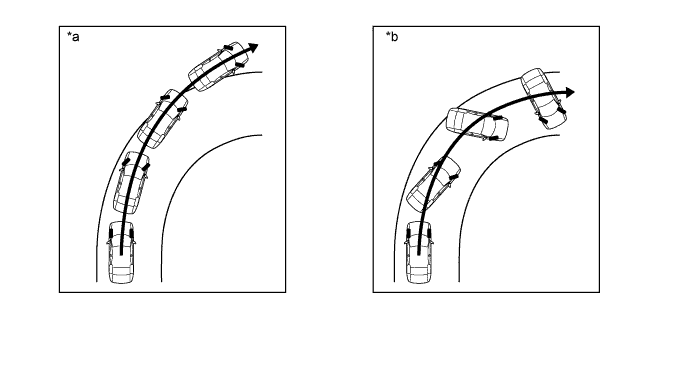
Anti-lock Brake System (ABS)
-
The ABS helps prevent the wheels from locking during sudden braking or braking on a slippery surface. This helps provide the appropriate braking force for the road surface conditions, thus ensuring vehicle stability and excellent braking performance.
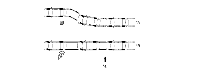
Text in Illustration *A With ABS *B Without ABS *a Brake Operation - -
-
-
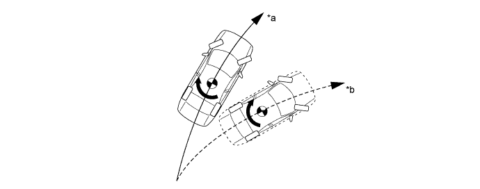
Electronic Brake Force Distribution (EBD)
-
This function controls the brake force that acts on the rear wheels in accordance with the changes in the vehicle conditions such as load factors or deceleration, in order to ensure excellent braking performance.
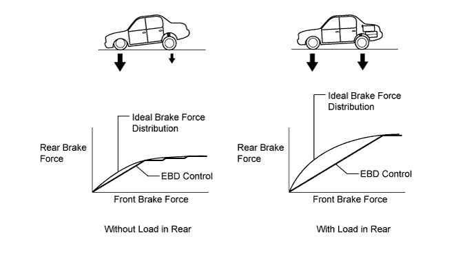
-
During braking while cornering, this function controls the brake force that acts on the left and right wheels in accordance with the vehicle conditions at that time. This ensures vehicle stability and excellent braking performance.

Text in Illustration 
Brake Force 
Control Moment
-
-
Brake Assist
-
With brake assist, based on the signals from the master cylinder pressure sensor, the skid control ECU calculates the speed with which and the amount the brake pedal is applied to determine if the driver is attempting emergency braking. If the skid control ECU determines that the driver is attempting emergency braking, the brake assist function activates the brake actuator to increase the brake fluid pressure, which increases the brake force.
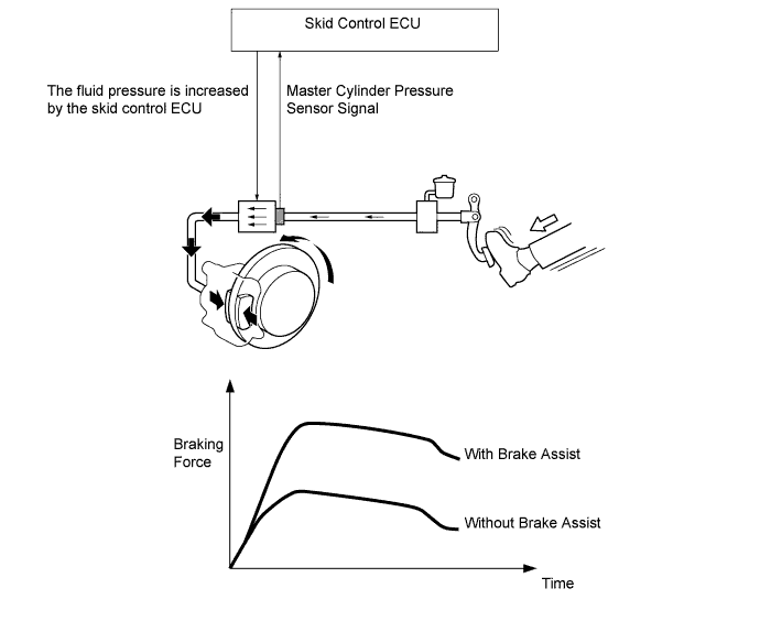
-
-
Traction Control (TRC)
-
TRC helps prevent the drive wheels from slipping if the driver depresses the accelerator pedal excessively when starting off or accelerating on a slippery surface. Together with hydraulic control of the drive wheels, the skid control ECU requests the ECM to perform engine output control. This produces drive force suited to the driving conditions in order to ensure proper start-off acceleration.
Text in Illustration *A Without TRC *B With TRC *1 Engine *2 ECM *3 Brake Actuator Assembly
- Skid Control ECU
- - *a Excessive drive force causes the drive wheels to slip *b Regulation of the throttle to control engine output 
Slippery Surface - -
-
-
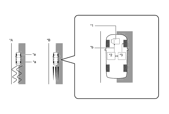
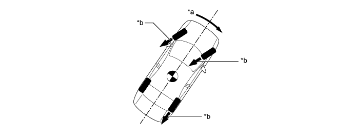
Vehicle Stability Control (VSC)
-
The following 2 examples can be considered as circumstances in which the tires exceed their lateral grip limit. VSC is designed to help control the vehicle behavior by controlling the engine output and the brakes at each wheel when the vehicle is subject to one of the conditions indicated below.
Text in Illustration *a Understeer Tendency *b Oversteer Tendency -
To determine the condition of the vehicle, sensors detect the steering angle, vehicle speed, vehicle's yaw rate, and the vehicle's lateral acceleration, which are then calculated by the skid control ECU.
-
Whether or not the vehicle is experiencing understeer is determined by the difference between the target yaw rate and the vehicle's actual yaw rate. When the vehicle's actual yaw rate is smaller than the target yaw rate (a target yaw rate is determined based on the vehicle speed and steering angle) that should be generated when the driver operates the steering wheel, it means the vehicle is making a turn at a greater angle than the target locus of travel. Thus, the skid control ECU determines that there is a large understeer tendency.
Text in Illustration *a Actual Locus of Travel (Actual Yaw Rate) *b Locus of Travel Based on the Target Yaw Rate -
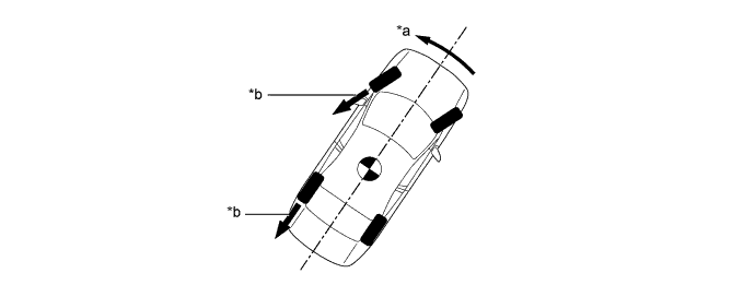
Whether or not the vehicle is experiencing oversteer is determined by the values of the vehicle's slip angle and the vehicle's slip angular velocity (time-dependent changes in the vehicle's slip angle). When the vehicle's slip angle is large, and the slip angular velocity is also large, the skid control ECU determines that the vehicle has a large oversteer tendency.

Text in Illustration *a Slip Angle *b Direction of Travel of the Vehicle's Center of Gravity *c Movement of Vehicle - - -
When the skid control ECU determines that the vehicle exhibits a tendency to experience either understeer or oversteer, it decreases the engine output and applies the brakes of the front or rear wheels to control the vehicle's yaw moment. The basic operation of the VSC functions is described below. However, the control method differs depending on the vehicle's characteristics and driving conditions.
-
When the skid control ECU determines that there is a large understeer tendency, it takes countermeasures in accordance with the extent of that tendency. The skid control ECU controls the engine output and applies the brake of the front wheels and rear wheel of the inner circle of the turn in order to help restrain the understeer tendency.
Text in Illustration (Making a Right Turn:) *a Control Moment *b Braking Force -
When the skid control ECU determines that there is a large oversteer tendency, it takes countermeasures in accordance with the extent of that tendency. It applies the brakes of the front wheel and rear wheel of the outer circle of the turn, and generates an outward moment of inertia in the vehicle, in order to restrain the oversteer tendency. Along with the reduction in the vehicle speed caused by the braking force, excellent vehicle stability is ensured.
Text in Illustration (Making a Right Turn:) *a Control Moment *b Braking Force
-
-
Cooperative Control with EPS
-
If the driver suddenly applies the brakes on a road surface with a considerable difference in friction coefficient between the right and left wheels, the difference in the brake force between the right and left wheels will cause the vehicle posture to become unstable and create a yaw moment. In this state, the skid control ECU controls the ABS and VSC to stabilize the vehicle posture. At the same time, it effects cooperative control with the EPS to provide steering torque assist, which facilitates the driver's steering maneuvers to stabilize the vehicle posture.
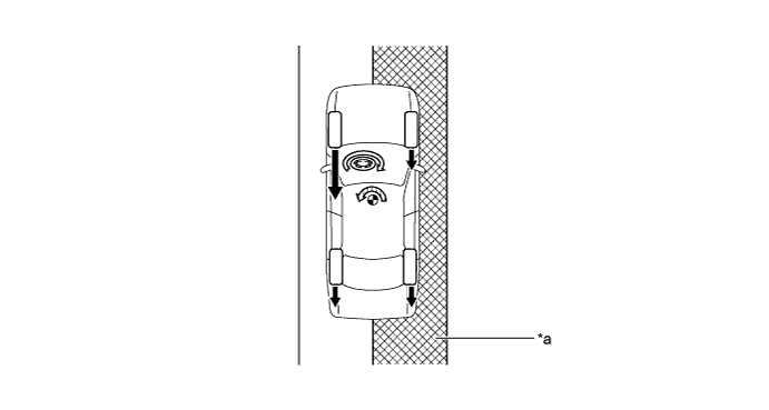
Text in Illustration *a Slippery Surface - - Brake Force Assist Direction 
Yaw Moment During Brake Controlling - - -
If the driver suddenly starts off or accelerates on a road surface with a considerable difference in friction coefficient between the right and left wheels, the slippage of a drive wheel will cause the vehicle posture to become unstable and negatively affect its acceleration performance. In this state, the skid control ECU causes the TRC to control the hydraulic brake of the slipping drive wheel, and requests the ECM to effect engine output control. At the same time, it effects cooperative control with the EPS to provide steering torque assist, which facilitates the driver's steering maneuvers to stabilize the vehicle posture.
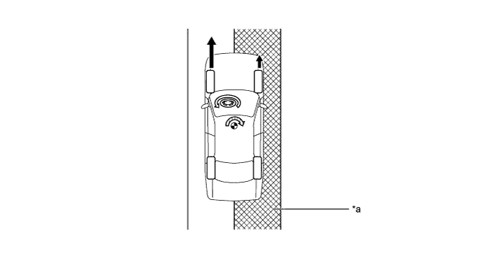
Text in Illustration *a Slippery Surface - - Drive Force Assist Direction Yaw Moment During Acceleration - - -
When the skid control ECU determines that front wheel skid is occurring, it controls the VSC to dampen the front wheel skid. At the same time, it performs cooperative control with the EPS to provide steering torque assist, which helps the driver control the driver's steering maneuvers used to stabilize the vehicle posture.
-
Steering torque assist provides the following functions:
-
Steering torque assist is used to inform the driver of a front wheel skid.
-
If the driver turns the steering wheel excessively, steering torque assist provides assistance to counter the excessive steering input.
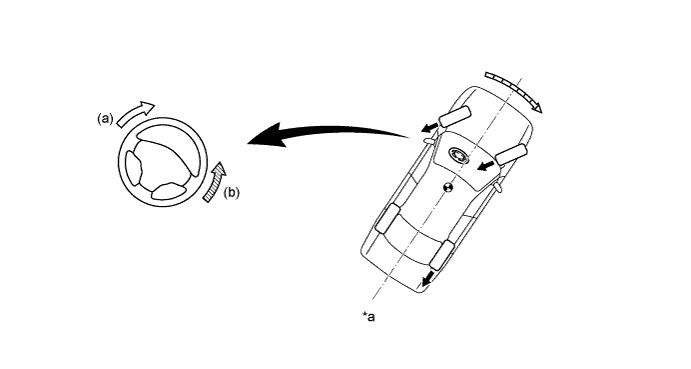
Text in Illustration *a Front Wheel Skid Tendency - - Brake Force Assist Direction to Indicate Front Wheel Skid Assist Direction to Counter Excessive Steering Input 
Control Moment
-
-
When the skid control ECU determines a rear wheel skid tendency, it controls the VSC to dampen the rear wheel skid. At the same time, it effects the cooperative control with the EPS to provide steering torque assist, which facilitates the driver's steering maneuvers in the direction to correct the rear wheel skid.
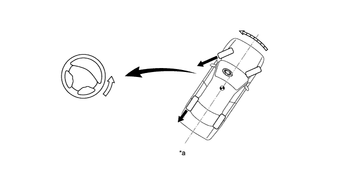
Text in Illustration *a Rear Wheel Skid Tendency - - Brake Force Assisting Direction Control Moment - -
-
-
Brake Control (Operating Dynamic Radar Cruise Control System)
-
If the distance from the vehicle ahead decreases during a dynamic radar cruise control system operation, it might not be possible for the vehicle to attain a sufficient amount of deceleration by restraining the engine output controlled by the ECM. In this instance, even if the driver is not depressing the brake pedal, the skid control ECU activates the brake actuator and starts braking, in order to attain the target deceleration rate that is constantly calculated and requested by the driving support ECU assembly. As a result, the stop lights illuminate.
-
At the end of braking, the skid control ECU gradually decreases the braking force and ends it in order to decelerate smoothly.
-
If further deceleration is required, the system sounds a skid control buzzer assembly to alert the driver to apply the brakes.
-
-
Brake Control (Operating Pre-crash Safety System)
-
If the driving support ECU assembly determines that the possibility of a collision is high, the ECU sends the pre-crash brake assist request signal to the skid control ECU. Upon receiving the signal, the skid control ECU switches the brake assist to standby mode. When the driver depresses the brake pedal, the skid control ECU operates the brake assist based on the master cylinder pressure sensor.
-
If the driving support ECU assembly determines an unavoidable collision, the ECU sends the pre-crash brake request signal to the skid control ECU. The skid control ECU then activates the brake actuator as a pre-crash brake control and decelerates the vehicle. Thus, the system helps to lessen impact in collision.
-
If the skid control ECU determines that the pedal depression force and braking force are both small when the brake assist is activated, the skid control ECU immediately activates the pre-crash brake control to ensure the braking force.
-
-
Emergency Brake Signal
-
The emergency brake signal automatically flashes all the stop lights in the case of emergency braking in order to reduce the risk of being rear ended by a following vehicle.
-
The skid control ECU detects the vehicle condition and braking operation using the speed sensors, yawrate sensor (airbag sensor assembly) and stop light switch assembly.
-
If emergency braking is detected based on these various signals, the skid control ECU sends an instruction to the stop light control ECU assembly to flash the stop lights.
-
-
-
FUNCTION
-
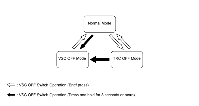
VSC OFF Switch
-
The operation of the VSC and TRC functions can be stopped by the VSC OFF switch. While the vehicle is being driven off the shoulder of the road or a dirt road, the engine output control is stopped to maintain drive torque.
-
The VSC OFF switch can select 3 modes (Normal Mode, TRC OFF Mode, VSC OFF Mode). When the VSC OFF switch is pressed briefly, TRC OFF Mode is entered and the TRC function will be disabled. When the VSC OFF switch is pressed and held for 3 seconds or more, VSC OFF Mode is entered and the TRC and VSC functions will be disabled.
-
After the power source is turned off while the vehicle is in TRC OFF Mode or VSC OFF Mode, turning the power source on again selects Normal Mode. The system also enters Normal Mode automatically when the vehicle speed increases.
-
The operations of the brake control functions in each mode are as follows:
Item Brake Control Function TRC OFF Indication on Multi-information Display VSC OFF Indicator Light TRC VSC Normal Mode ○ ○ Not Displayed Light Off TRC OFF Mode - ○ Displayed Light Off VSC OFF Mode - -* Displayed Light On Tech Tips
○: Controllable
-: Not Controllable
*: The control is effected during braking or while the yaw rate is large.
-
-
-
CONSTRUCTION
-
Brake Actuator Assembly
-
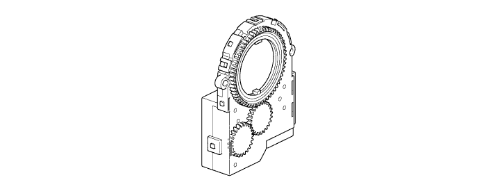
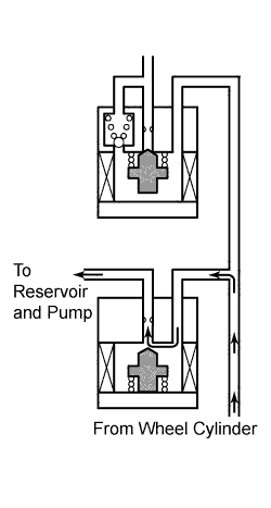
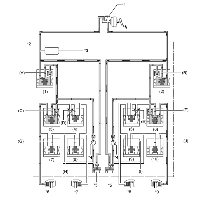
The brake actuator assembly consists of the actuator portion and skid control ECU.
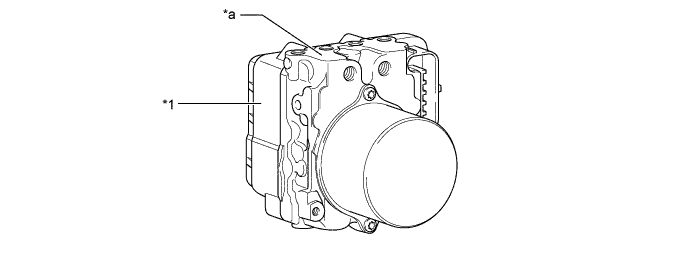
Text in Illustration *1 Skid Control ECU - - *a Actuator Portion - - -
The actuator portion consists of 2 master cylinder cut solenoid valves, 4 pressure holding solenoid valves, 4 pressure reduction solenoid valves, 2 pumps, 2 reservoirs, and a master cylinder pressure sensor.
-
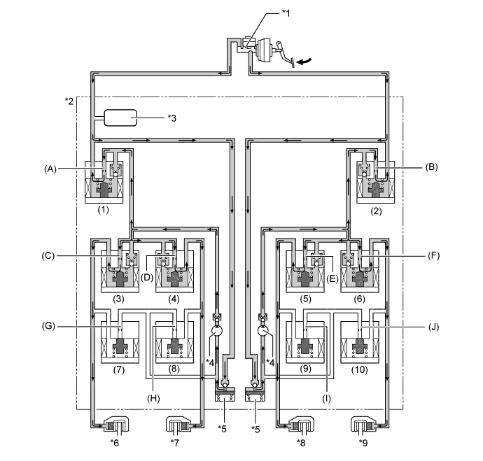
The brake actuator is constructed with the following hydraulic circuit:
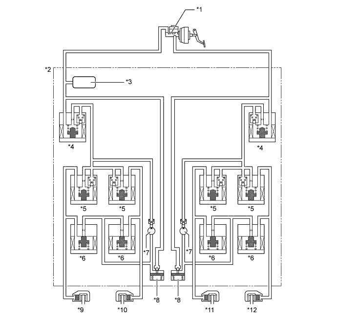
Text in Illustration *1 Brake Master Cylinder Sub-assembly *2 Brake Actuator Assembly *3 Master Cylinder Pressure Sensor *4 Master Cylinder Cut Solenoid Valve *5 Pressure Holding Solenoid Valve *6 Pressure Reduction Solenoid Valve *7 Pump *8 Reservoir *9 Front Brake Caliper (Left Side) *10 Rear Brake Caliper (Right Side) *11 Rear Brake Caliper (Left Side) *12 Front Brake Caliper (Right Side)
-
-
Speed Sensor
-
An active type speed sensor is used. This sensor contains a sensor IC.
-
The front speed sensors use a gear type rotor that is mounted on the drive shaft.
-
The rear speed sensors use a magnet type sensor rotor, which consists of N and S poles that are arranged in a circle. The rear speed sensor rotor is integrated with the hub bearing inner race.
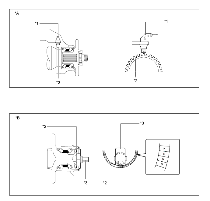
Text in Illustration *A Front *B Rear *1 Front Speed Sensor *2 Sensor Rotor *3 Rear Speed Sensor - - -
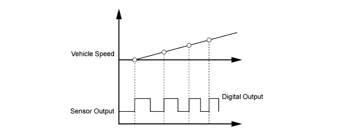
The active type speed sensor uses a sensor IC to detect magnetic field changes caused when the sensor rotor rotates, and the sensor outputs the detected information to the skid control ECU as digital pulses (vehicle speed signal).
-
To detect the vehicle speed, the frequency of the output pulses is used. Because the active type sensor outputs digital pulses, it can detect the vehicle speed even when the vehicle is nearly stationary.
-
-
Steering Sensor
-
The steering sensor detects the steering direction and angle, and sends this signal to the skid control ECU.
Tech Tips
When removing and reinstalling the steering sensor, it is necessary to use a special procedure to prevent the center position of the steering sensor from becoming misaligned. For details, refer to the Repair Manual.
-
-
Airbag Sensor Assembly
-
The airbag sensor assembly incorporates the acceleration sensor and yawrate sensor.
-
The yawrate sensor detects the vehicle's yaw rate.
-
The acceleration sensor detects the vehicle's longitudinal and lateral acceleration.
-
-
-
OPERATION
-
ABS with EBD
-
Based on the signals received from the 4 speed sensors and airbag sensor assembly, the skid control ECU calculates each wheel speed and deceleration, and checks wheel slipping conditions. According to the slipping condition, the skid control ECU controls the pressure holding solenoid valve and pressure reduction solenoid valve in order to adjust the fluid pressure of each wheel cylinder in the following 3 modes: pressure reduction, pressure holding, and pressure increase modes.
Not Activated Normal Braking - - Activated Increase Mode Holding Mode Reduction Mode Hydraulic Circuit 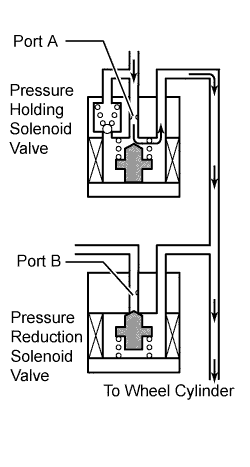
Pressure Holding Valve (Port A) OFF (Open) ON (Closed) ON (Closed) Pressure Reduction Valve (Port B) OFF (Closed) OFF (Closed) ON (Open) Brake Wheel Cylinder Pressure Increased Held Reduced
-
-
Brake Assist
-
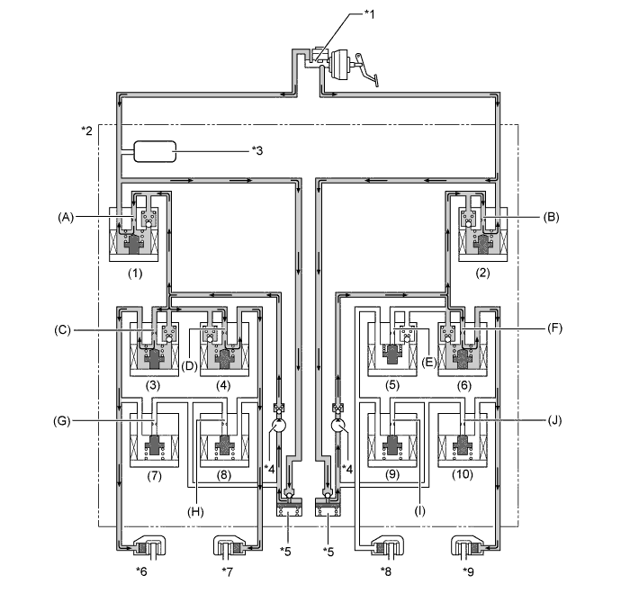
In the event of emergency braking, the skid control ECU determines the driver's intentions based on the speed of the pressure increase in the master cylinder detected by the master cylinder pressure sensor signal. If the skid control ECU judges the need for additional brake assist, pressure to supplement the amount provided by the master cylinder is generated by the pump in the brake actuator and directed to each wheel cylinder.
-
The skid control ECU also provides brake assist in the event of a brake booster failure. The skid control ECU judges a brake booster failure using the brake load sensing switch and master cylinder pressure sensor signals.
Text in Illustration (Brake Assist Operation:) *1 Brake Master Cylinder Sub-assembly *2 Brake Actuator Assembly *3 Master Cylinder Pressure Sensor *4 Pump *5 Reservoir *6 Front Brake Caliper (Left Side) *7 Rear Brake Caliper (Right Side) *8 Rear Brake Caliper (Left Side) *9 Front Brake Caliper (Right Side) - - -
Each valve operates as shown below:
Item Port Brake Assist Not Activated Brake Assist Activated Master Cylinder Cut Solenoid Valves (1), (2) (A), (B) OFF (Open) ON* Front Brakes Pressure Holding Solenoid Valves (3), (6) (C), (F) OFF (Open) OFF (Open) Pressure Reduction Solenoid Valves (7), (10) (G), (J), OFF (Closed) OFF (Closed) Rear Brakes Pressure Holding Solenoid Valves (4), (5) (D), (E) OFF (Open) OFF (Open) Pressure Reduction Solenoid Valves (8), (9) (H), (I) OFF (Closed) OFF (Closed) Pump OFF ON *: Hydraulic pressure is controlled by continuously cycling the solenoid valves between open and closed, according to the operating conditions.
-
-
TRC
-
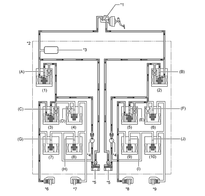
The fluid pressure generated by the pump is regulated by the master cylinder cut solenoid valve to achieve the required pressure. Thus, the brakes for the drive wheels are controlled in the following 3 modes: pressure reduction, pressure holding, and pressure increase modes, to control slippage of the drive wheels.
-
The diagram shows the hydraulic circuit in pressure increase mode when TRC is activated. The pressure holding solenoid valve and the pressure reduction solenoid valve are turned ON/OFF according to the ABS with EBD operation pattern.
Text in Illustration (TRC Operation:) *1 Brake Master Cylinder Sub-assembly *2 Brake Actuator Assembly *3 Master Cylinder Pressure Sensor *4 Pump *5 Reservoir *6 Front Brake Caliper (Left Side) *7 Rear Brake Caliper (Right Side) *8 Rear Brake Caliper (Left Side) *9 Front Brake Caliper (Right Side) - - -
Each valve operates as shown below:
Item Port TRC Not Activated TRC Activated Increase Mode Holding Mode Reduction Mode Master Cylinder Cut Solenoid Valve (1), (2) (A), (B) OFF (Open) ON* ON* ON* Front Brakes Pressure Holding Solenoid Valve (3), (6) (C), (F) OFF (Open) OFF (Open) ON (Closed) ON (Closed) Pressure Reduction Solenoid Valve (7), (10) (G), (J) OFF (Closed) OFF (Closed) OFF (Closed) ON (Open) Brake Wheel Cylinder Pressure - - - Increased Held Reduced Rear Brakes Pressure Holding Solenoid Valve (4), (5) (D), (E) OFF (Open) ON (Closed) ON (Closed) ON (Closed) Pressure Reduction Solenoid Valve (8), (9) (H), (I) OFF (Closed) OFF (Closed) OFF (Closed) OFF (Closed) Brake Wheel Cylinder Pressure - - - - - - Pump OFF ON ON ON *: Hydraulic pressure is controlled by continuously cycling the solenoid valves between open and closed, according to the operating conditions.
-
-
VSC
-
VSC, by way of solenoid valves, controls the fluid pressure generated by the pump and applies it to each wheel cylinder in the following 3 modes: pressure reduction, pressure holding, and pressure increase modes. As a result, understeer and oversteer tendencies are controlled.
-
In understeer restraining control, the skid control ECU controls engine output and applies the brakes of the front and rear wheels on the inside of the turn. Also, depending on whether the brakes are applied and the vehicle condition, there are circumstances in which the brake of a specific wheel may not be applied even if it was targeted for braking. The diagram below shows the hydraulic circuit in pressure increase mode, as it restrains an understeer tendency while the vehicle is making a right turn. In other operating modes, the pressure holding valve and the pressure reduction valve are turned ON/OFF according to the ABS with EBD operation pattern.
Text in Illustration (VSC Operation (Understeer Restraining Control):) *1 Brake Master Cylinder Sub-assembly *2 Brake Actuator Assembly *3 Master Cylinder Pressure Sensor *4 Pump *5 Reservoir *6 Front Brake Caliper (Left Side) *7 Rear Brake Caliper (Right Side) *8 Rear Brake Caliper (Left Side) *9 Front Brake Caliper (Right Side) - - -
Each valve operates as shown below:
Item Port VSC Not Activated VSC Activated Increase Mode Holding Mode Reduction Mode Master Cylinder Cut Solenoid Valve (1), (2) (A), (B) OFF (Open) ON* ON* ON* Front Brakes Pressure Holding Solenoid Valve (3) (C) OFF (Open) OFF (Open) ON (Closed) ON (Closed) (6) (F) OFF (Open) OFF (Open) ON (Closed) ON (Closed) Pressure Reduction Solenoid Valve (7) (G) OFF (Closed) OFF (Closed) OFF (Closed) ON (Open) (10) (J) OFF (Closed) OFF (Closed) OFF (Closed) ON (Open) Brake Wheel Cylinder Pressure Right - - - Increased Held Reduced Left - - - Increased Held Reduced Rear Brakes Pressure Holding Solenoid Valve (4) (D) OFF (Open) OFF (Open) ON (Closed) ON (Closed) (5) (E) OFF (Open) ON (Closed) ON (Closed) ON (Closed) Pressure Reduction Solenoid Valve (8) (H) OFF (Closed) OFF (Closed) OFF (Closed) ON (Open) (9) (I) OFF (Closed) OFF (Closed) OFF (Closed) ON (Open) Brake Wheel Cylinder Pressure Right - - - Increased Held Reduced Left - - - - - - Pump OFF ON ON ON *: Hydraulic pressure is controlled by continuously cycling the solenoid valves between open and closed, according to the operating conditions.
-
In oversteer restraining control, the skid control ECU applies the brakes of the front and rear wheels on the outside of the turn. Also, depending on whether the brakes are applied and the vehicle condition, the brake of a specific wheel may not be applied even if it was targeted for braking. The diagram below shows the hydraulic circuit in pressure increase mode, as it restrains an oversteer tendency while the vehicle is making a right turn. In other operating modes, the pressure holding valve and the pressure reduction valve are turned ON/OFF according to the ABS with EBD operation patterns.
Text in Illustration (VSC Operation (Oversteer Restraining Control):) *1 Brake Master Cylinder Sub-assembly *2 Brake Actuator Assembly *3 Master Cylinder Pressure Sensor *4 Pump *5 Reservoir *6 Front Brake Caliper (Left Side) *7 Rear Brake Caliper (Right Side) *8 Rear Brake Caliper (Left Side) *9 Front Brake Caliper (Right Side) - - -
Each valve operates as shown below:
Item Port VSC Not Activated VSC Activated Increase Mode Holding Mode Reduction Mode Master Cylinder Cut Solenoid Valve (1), (2) (A), (B) OFF (Open) ON* ON* ON* Front Brakes Pressure Holding Solenoid Valve (3) (C) OFF (Open) OFF (Open) ON (Closed) ON (Closed) (6) (F) OFF (Open) ON (Closed) ON (Closed) ON (Closed) Pressure Reduction Solenoid Valve (7) (G) OFF (Closed) OFF (Closed) OFF (Closed) ON (Open) (10) (J) OFF (Closed) OFF (Closed) OFF (Closed) OFF (Closed) Brake Wheel Cylinder Pressure Right - - - - - - Left - - - Increased Held Reduced Rear Brakes Pressure Holding Solenoid Valve (4) (D) OFF (Open) ON (Closed) ON (Closed) ON (Closed) (5) (E) OFF (Open) OFF (Open) ON (Closed) ON (Closed) Pressure Reduction Solenoid Valve (8) (H) OFF (Closed) OFF (Closed) OFF (Closed) OFF (Closed) (9) (I) OFF (Closed) OFF (Closed) OFF (Closed) ON (Open) Brake Wheel Cylinder Pressure Right - - - - - - Left - - - Increased Held Reduced Pump OFF ON ON ON *: Hydraulic pressure is controlled by continuously cycling the solenoid valves between open and closed, according to the operating conditions.
-
-
Brake Control Operation (Operating Dynamic Radar Cruise Control)
-
The skid control ECU operates the brakes by receiving a motive force request signal from the driving support ECU assembly while the dynamic radar cruise control system is being activated. This brake control operates in the same way as the normal brake operation.
-
-
Brake Control Operation (Operating Pre-crash Safety System)
-
If the driving support ECU assembly determines that the possibility of a collision is high, the ECU sends the pre-crash brake assist request signal to the skid control ECU. Upon receiving the signal, the skid control ECU switches the brake assist to standby mode. When the driver depresses the brake pedal, the skid control ECU operates the brake assist based on the master cylinder pressure sensor.
-
If a collision is unavoidable, the skid control ECU actuates the motor in the power supply portion to apply direct pressure to the wheel cylinders even if the driver does not depress the brake pedal. This brake control operates in the same way as the normal brake operation.
-
-
VSC (Cooperative Control with EPS)
-
The operation of the solenoid valves under the cooperative control with EPS is the same as the operation of the brake control functions (ABS, TRC, VSC).
-
-
-
FAIL-SAFE
-
If a failure occurs in the skid control ECU, sensors, or brake actuator assembly, the system continues performing brake control by excluding the failed area and using only the areas that are operating normally.
-
-
DIAGNOSIS
-
If the skid control ECU detects a malfunction in the brake control system, the warning lights or indicator light illuminate. At the same time, a Diagnostic Trouble Code (DTC) is stored in the memory of the skid control ECU.
-
This system has a sensor signal check (test mode) function.
-
For details of DTCs and the check function, refer to the Repair Manual.
-