LANE DEPARTURE ALERT SYSTEM DETAILS
-
FUNCTION OF MAIN COMPONENTS
Components Function Combination Meter Assembly LDA Indicator Light Illuminates or turns off to warn the driver in accordance with signals from the lane departure warning camera. Multi-information Display Displays a warning message to inform or warn the driver of the system condition in accordance with signals from the lane departure warning camera. Master Warning Light Illuminates to warn the driver in accordance with signals from the lane departure warning camera. Buzzer Sounds to warn the driver in accordance with signals from the lane departure warning camera. Lane Departure Warning Camera
-
Captures the road view ahead of the vehicle and detects lane markers on the driving lane, and calculates the radius to the center of the lane, lane width, distance from markers and heading angle deviation.
-
Controls the lane departure alert system.
-
Transmits the indicator light illumination request signal, multi-information display indication request signal, and buzzer sound request signal to the combination meter assembly.
Driving Support ECU Assembly* Transmits data between the CAN V bus and CAN sub bus 13. ECM Transmits the reverse signal to the lane departure warning camera. Brake Actuator Assembly Skid Control ECU
-
Sends a vehicle speed signal from the speed sensor to the lane departure warning camera.
-
Sounds the skid control buzzer assembly in accordance with a request signal from the lane departure warning camera.
Steering Pad Switch Assembly LDA Switch Detects an on/off status of the system and transmits a signal to the lane departure warning camera. Headlight Dimmer Switch Assembly Transmits a turn signal command to the lane departure warning camera. Airbag Sensor Assembly Yawrate Sensor Detects yaw rate and transmits a signal to the lane departure warning camera. Speed Sensor Transmits a vehicle speed signal to the skid control ECU. Skid Control Buzzer Assembly Sounds to warn the driver in accordance with signals from the lane departure warning camera. Main Body ECU (Multiplex Network Body ECU) Sends country specification information signals to the lane departure warning camera. *: Models with dynamic radar cruise control system
-
-
FUNCTION
-
Lane Departure Warning Camera
-
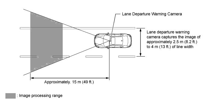
The lane departure warning camera captures the road image up to approximately 15 m (49 ft.) ahead of the vehicle.
-
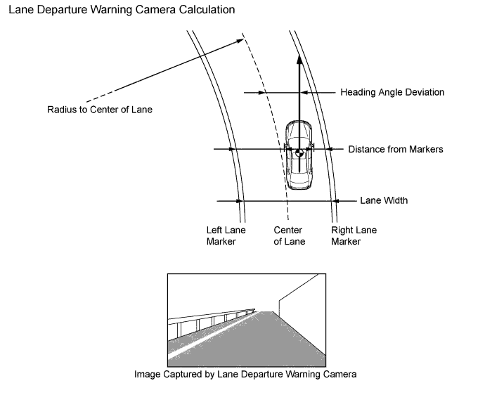
The lane departure warning camera detects lane markers and calculates the radius to the center of the lane, heading angle deviation, lateral deviation from the center of the lane, and the lane width.
Tech Tips
When one of the following operations is conducted, the lane departure warning camera angle must be adjusted. For details, refer to the Repair Manual.
-
The lane departure warning camera is removed and reinstalled or replaced.
-
Parts relating to the tire or suspension are replaced or adjusted.
-
Strong force is applied onto the lane departure warning camera.
-
-
By processing the road image data, the lane departure warning camera detects lane markers and calculates the radius to the center of the lane, heading angle deviation, the distances from the markers, and the lane width.
-
-
-
OPERATING CONDITION
-
Operating Conditions of Lane Departure Alert System
Operation Condition Operating/Resume The lane departure warning function is activated when all of the following conditions are met:
-
The LDA switch is on. (When the LDA switch is pressed to turn on the LDA system, the LDA indicator light illuminates.)
-
The vehicle speed is between approx. 50 km/h (31 mph) and 210 km/h (130 mph).
-
Lane markers are detected.
-
No turn signal command is detected.
-
System malfunction is not detected.
Suspended The lane departure alert system is suspended when any one of the following conditions is met:
-
The vehicle speed is not between approx. 50 km/h (31 mph) and 210 km/h (130 mph).
-
A turn signal command is detected.
-
No lane markers are detected.
-
Immediately after the lane departure warning is activated.
The lane departure warning function is suspended for at least 2 second when any of the conditions above are met. This function resumes when normal operating conditions return.
Canceled The lane departure alert system is stopped when any one of the following conditions is met:
-
The LDA switch is off.
-
The lane departure alert system is malfunctioning.
-
The temperature of the lane departure warning camera is abnormal.
The lane departure alert system resumes when the following conditions are met:
-
The conditions to start operation listed above returns to are satisfied.
-
The lane departure alert system condition returns to normal.
-
The engine switch is turned off and on (IG) again to ensure normal operation, after the lane departure alert system has been stopped by a system malfunction.
-
-
-
OPERATION
-
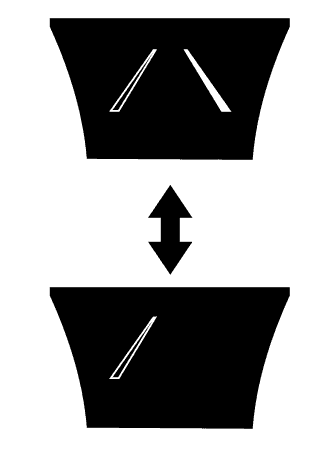
The lane departure warning camera calculates the estimated position which the front wheel will reach based on the information collected, vehicle speeds and front wheel positions. When the lane departure warning camera determines that the front wheel is about to cross the lane marker, the lane departure warning camera activates the lane departure alert system, displays a warning indicator on the multi-information display and sounds the skid control buzzer assembly.
-
The lane departure alert system does not operate if the vehicle approaches the lane marker (but does not cross it), as long as the vehicle remains parallel with the lane marker.
-
Combination Meter Assembly
-
The combination meter assembly illuminates the indicator lights or displays an indicator on the multi-information display, and sounds a buzzer (which is built into the combination meter assembly) or skid control buzzer assembly in accordance with the respective condition.
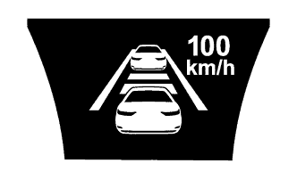
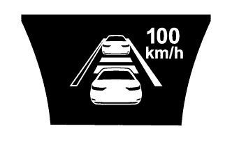
Lane Departure Alert System On and Radar Cruise Control System Off Condition Multi-information Display 
Skid Control Buzzer Assembly
-
Approximately 50 km/h to 210 km/h (31 mph to 130 mph)
-
Lane Markers Detected

Illuminated -
-
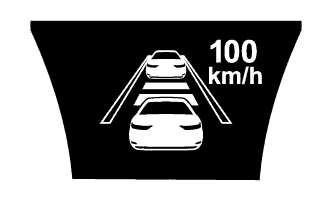
Approximately 50 km/h to 210 km/h (31 mph to 130 mph)
-
One Lane Marker Detected

-
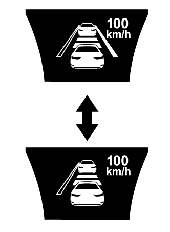
Approximately 50 km/h to 210 km/h (31 mph to 130 mph)
-
Warning Operating
Illuminated Sounds continuously The lane marker icons blink
-
Approximately 50 km/h (31 mph) or Higher
-
Lane Markers Not Detected

Illuminated - Below Approximately 50 km/h (31 mph) Lane Departure Alert System On and Radar Cruise Control System On Condition Multi-information Display Skid control buzzer assembly
-
Approximately 50 km/h to 170 km/h (31 mph to 105 mph)
-
Lane Markers Detected
Illuminated -
-
Approximately 50 km/h to 170 km/h (31 mph to 105 mph)
-
One Lane Marker Detected
Illuminated -
-
Approximately 50 km/h to 170 km/h (31 mph to 105 mph)
-
Lane Markers Not Detected
Illuminated -
-
Approximately 50 km/h to 170 km/h (31 mph to 105 mph)
-
Lane Markers Detected
-
Lane Deviation Warning Operating
Illuminated Sounds Countinuously The lane marker icons blink Warning Messages Condition Multi-information Display 
Buzzer in the combination meter assembly Temperature of Lane Departure Warning Camera is Abnormal. 
- Illuminated - System Malfunction 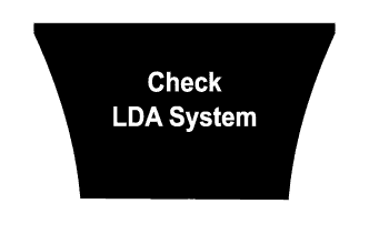
- Illuminated Sounds Lane Departure Warning Camera Angle Being Adjusted 
- - - -
-
-
-
DIAGNOSIS
-
If a malfunction is detected in the lane departure alert system the lane departure warning camera cancels the lane departure alert system, turns off the LDA indicator light and illuminates the master warning light, sounds the buzzer in the combination meter assembly, and displays a message on the multi-information display to inform the driver of the malfunction.
-
At the same time, the malfunction is stored in memory as a Diagnostic Trouble Code (DTC). When a Global TechStream (GTS) is connected to the DLC3, the DTC can be read. For details, refer to the Repair Manual.
-