TIRE PRESSURE WARNING SYSTEM DETAILS
-
FUNCTION OF MAIN COMPONENTS
Component Function Tire Pressure Warning Valve and Transmitter
-
Detects the tire pressure, internal temperature and rotational acceleration of the tire and transmits the measured values and the ID code to the tire pressure warning ECU and receiver.
-
Receives radio waves for tire position determination from the initiators.
Front Tire Pressure Warning Initiator* Built into the front-left wheelhouse and sends the radio waves for tire position determination to the sending devices (tire pressure warning valve and transmitter). Rear Tire Pressure Warning Initiator* Built into the rear-left wheelhouse and sends the radio waves for tire position determination to the sending devices (tire pressure warning valve and transmitter). Tire Pressure Warning Initiator Driver* Operates the tire pressure warning initiators. Tire Pressure Warning ECU and Receiver
-
Receives the data from the tire pressure warning valve and transmitter and monitors the tire inflation pressure.
-
Outputs the respective signal to the main body ECU (multiplex network body ECU) when a drop in the tire inflation pressure, a system malfunction or the beginning of initialization is detected.
-
Instructs the initiator driver to determine tire positions.*
-
Confirms the positions of the tires in accordance with information about the intensity of radio waves for tire position determination from the tire pressure warning valve and transmitter, and sends a signal to display the tire pressure value (based on the measured value) on the multi-information display.*
Tire Pressure Warning Reset Switch The current tire pressures are stored in the tire pressure warning system as set pressures when the tire pressure warning reset switch is operated. Steering Pad Switch Assembly* DISP Switch Switches the information on the multi-information display to the tire pressure when pressed. Main Body ECU (Multiplex Network Body ECU) Receives the signal from the tire pressure warning ECU and receiver and outputs it to the combination meter assembly via CAN communication. Combination Meter Assembly Transmits the vehicle speed signal to the tire pressure warning ECU and receiver. Combination Meter Assembly Tire Pressure Warning Light
-
Illuminates or stays on after blinking for 1 minute to warn the driver in accordance with the signal from the tire pressure warning system.
-
Flashes 3 times after initialization.
Multi-information display* Displays the identified tire pressure and position to inform or warn the driver. Tech Tips
*: Models with tire inflation pressure display function
-
-
FUNCTION
-
Tire Inflation Pressure Display Function (Models with Tire Inflation Pressure Display Function)
-
The multi-information display shows the following to inform or warn the driver of the tire pressure:
Condition Multi-information Display Tire pressure is normal. 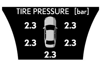
Tire pressure is below the warning threshold. 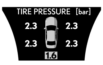
Tire position identification has not yet been completed. 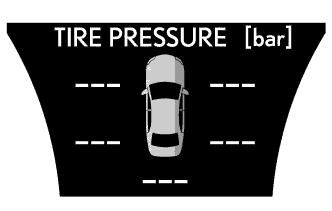
There is a system malfunction. 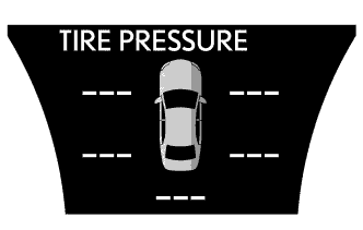
-
Identification of the tire position is carried out when the engine switch is turned on (IG) or when initialization is performed. However, under certain conditions, the tire position may not be displayed. In this case, radio wave conditions may be restored by continuously driving, thereby enabling tire position determination.
-
-
Warning Function
-
The tire pressure warning system has 2 warning methods that are used, depending on the condition detected.
-
The table below shows the warning methods for the tire pressure warning light in the combination meter assembly and the multi-information display.*
Tech Tips
*: Models with tire inflation pressure display function
Detection Condition Tire Pressure Warning Light Multi-information Display*1 The tire pressure warning system has detected that the tire pressure has become lower than the warning threshold. Illuminates*2 The tire pressure warning system has detected a malfunction in the system. Stays on after blinking for 1 minute*3 Tech Tips
*1: Models with tire inflation pressure display function
*2: If the tire pressure warning light illuminates, adjust the tire pressure.
*3: If the tire pressure warning light stays on after blinking for 1 minute, the system is malfunctioning and must be repaired in order to turn off the light. For details, refer to the Repair Manual.
-
-
Initial Check Function
-
After the engine switch is tuned on (IG), the tire pressure warning ECU and receiver illuminates the tire pressure warning light for 3 seconds to check the warning light circuits.
-
-
Initialization Function
-
The warning threshold is calculated from the tire inflation pressure valve at the time of initialization and memorized in the tire pressure warning ECU and receiver. Therefore, the tire pressure warning ECU and receiver should be initialized after:
-
The recommended tire inflation pressure changes due to changes in vehicle weight, speed conditions or tire size.
-
Replacement of the tire pressure warning ECU and receiver or a tire pressure warning valve and transmitter.
-
The tires are rotated on a vehicle with different recommended tire inflation pressures for the front and rear tires.
-
The tire pressure is adjusted.*
Tech Tips
*: Models compliant with ECE-R64 legal regulations
-
-
Before performing initialization, adjust the tire inflation pressure to the recommended pressure when the tires are cold. For details, refer to the Repair Manual.
-
Initialization starts after the tire pressure warning reset switch is pressed and held (with the engine switch on (IG) and the vehicle stopped) and the tire pressure warning light blinks slowly 3 times.
-
The tire pressure warning reset switch is not used to cancel the warning. Do not press the tire pressure warning reset switch to turn off the tire pressure warning light.*
Tech Tips
*: Models compliant with FMVSS138 legal regulations
-
-
-
CONSTRUCTION
-
Tire Pressure Warning Valve and Transmitter
-
The tire pressure warning valve and transmitters are integrated in the tire valves. Each transmitter consists of a lithium battery, sensor and transmitter.
-
Make sure not to damage the urethane covered backside of the transmitter (the surface opposite to the side with the ID code) with anything sharp.
-
The transmitter directly measures tire inflation pressure and temperature to see if the vehicle can continue to run.
-
The transmitter transmits the measured tire inflation pressure and temperature values to the tire pressure warning ECU and receiver on a frequency of 314.98 MHz*1 or 433.90 MHz*2.
Tech Tips
*1: Models compliant with FMVSS138 legal regulations
*2: Models compliant with ECE-R64 legal regulations
-
Depending on the timing of the data transmission, it may take several minutes to receive the data from the tire pressure warning valve and transmitter.
-
The ID code is written on the tire pressure warning valve and transmitter.
-
Signals are received from the tire pressure warning initiator.*
Tech Tips
*: Models with tire inflation pressure display function
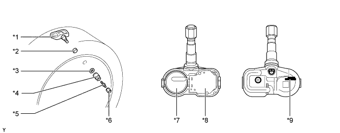
Text in Illustration *1 Tire Pressure Warning Valve and Transmitter *2 Grommet *3 Washer *4 Nut *5 Tire Valve Core *6 Tire Valve Cap *7 Lithium Battery *8 Sensor and Transmitter *9 ID Code (Hexadecimal 7 Digits) - - Tech Tips
-
The lithium batteries of the tire pressure warning valve and transmitters are nonreplaceable. If the battery is depleted, the tire pressure warning valve and transmitter must be replaced. (Battery life: approximately 10 years)
-
A new tire pressure warning valve and transmitter is shipped in sleep mode to prevent the battery from depleting in storage. When the tire inflation pressure in the detection portion of the tire pressure warning valve and transmitter increases or decreases by 20 kPa (0.2 kgf/cm2, 2.9 psi) within 20 seconds, the tire pressure warning valve and transmitter automatically cancels sleep mode. Once sleep mode is canceled, the tire pressure warning valve and transmitter cannot return to sleep mode.
-
When replacing a tire pressure warning valve and transmitter, each of the tire pressure warning valve and transmitter ID codes must be registered. If even one of the tire pressure warning valve and transmitters is replaced, the ID codes of all tire pressure warning valve and transmitters must be registered again. Record all existing ID codes before beginning the process to enter new ID codes.
-
To register an ID code, use the Global TechStream (GTS) to enter the ID code that is indicated on the tire pressure warning valve and transmitter.
-
Be careful not to damage the tire pressure warning valve and transmitters when removing and reinstalling them.
-
Replace the grommet, valve core, washer and nut with new ones when the tire pressure warning valve and transmitter is replaced or removed and reinstalled. This is necessary to ensure sealing performance.
-
When replacing a tire valve cap, use only the specified cap. If an unspecified cap is used, it may seize to the tire pressure warning valve and transmitter.
-
For details, refer to the Repair Manual.
-
-
-
-
DIAGNOSIS
-
To inform the driver when the tire pressure warning ECU and receiver detects a malfunction in the system, the tire pressure warning ECU and receiver will blink the tire pressure warning light for 1 minute, after which the light will stay on. It will also store the Diagnostic Trouble Codes (DTCs) in memory.
-
5-digit DTCs can be read by connecting the Global TechStream (GTS) to the DLC3. For details, refer to the Repair Manual.
-