NEW FEATURES
-
DESCRIPTION
-
nanoeTM*has been adopted and provided depending on the specifications.
Tech Tips
*: nanoeTMis a trademark of Panasonic Corporation.
-
-
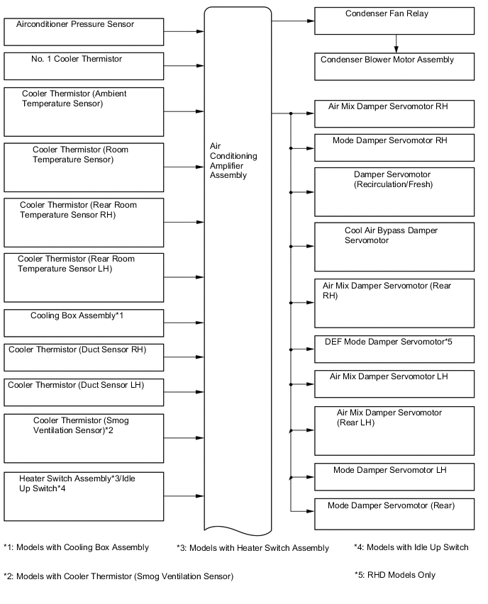
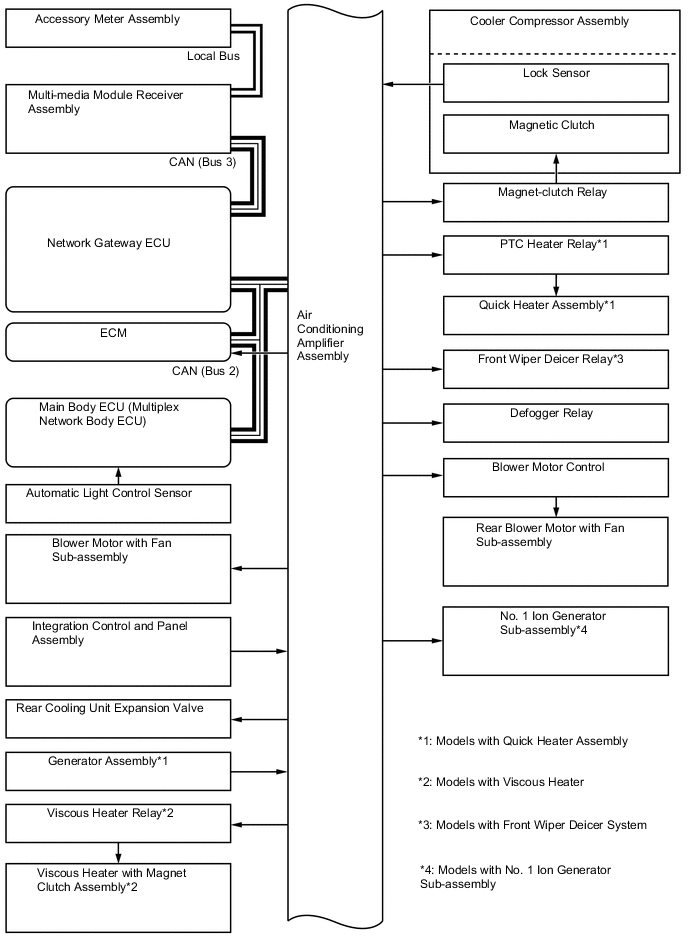
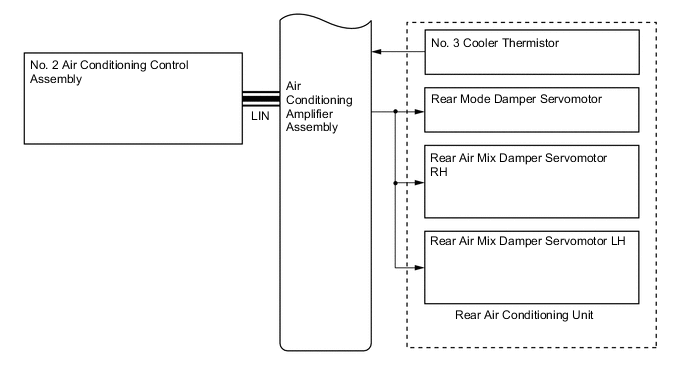
SYSTEM DIAGRAM
-
LAYOUT OF MAIN COMPONENTS
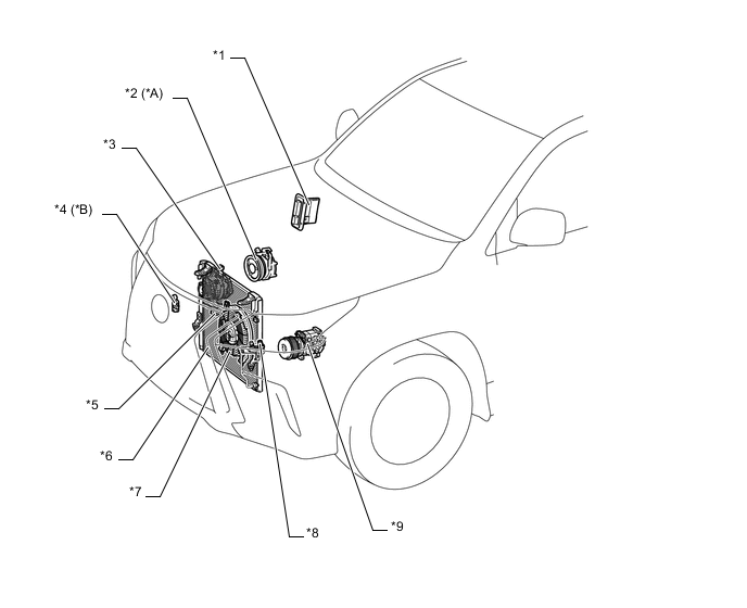
*A Models with Viscous Heater *B Models with Cooler Thermistor (Smog Ventilation Sensor) *1 ECM *2 Viscous Heater with Magnet Clutch Assembly *3 Generator Assembly *4 Cooler Thermistor (Smog Ventilation Sensor) *5 Cooler Thermistor (Ambient Temperature Sensor) *6 Cooler Condenser Assembly *7 Condenser Blower Motor Assembly *8 Airconditioner Pressure Sensor *9 Cooler Compressor Assembly - - 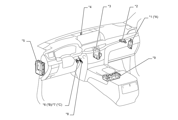
*A Models with No. 1 Ion Generator Sub-assembly *B Models with Idle Up Switch *C Models with Heater Switch Assembly - - *1 No. 1 Ion Generator Sub-assembly *2 Network Gateway ECU *3 Air Conditioning Amplifier Assembly *4 Automatic Light Control Sensor *5 Main Body ECU (Multiplex Network Body ECU) *6 Idle Up Switch *7 Heater Switch Assembly *8 Cooler Thermistor (Room Temperature Sensor) *9 Integration Control and Panel Assembly - - 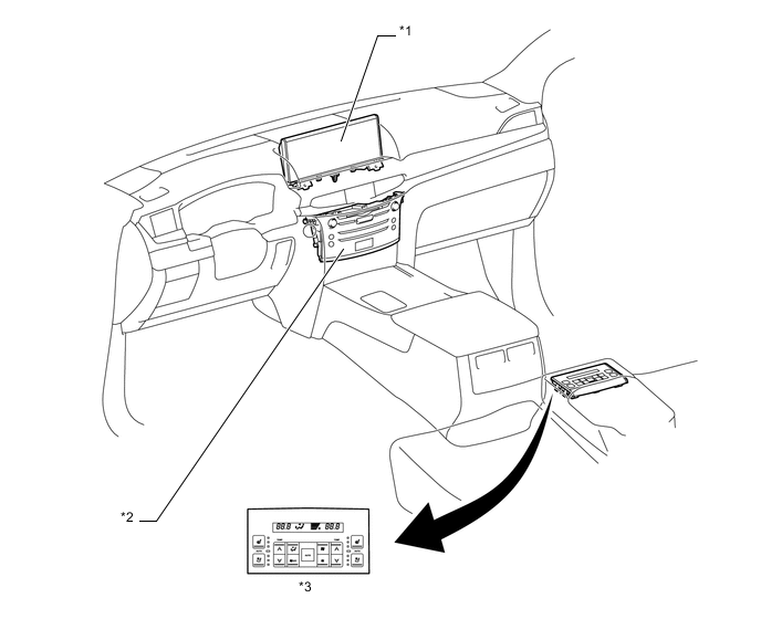
*1 Accessory Meter Assembly *2 Multi-media Module Receiver Assembly *3 No. 2 Air Conditioning Control Assembly - - 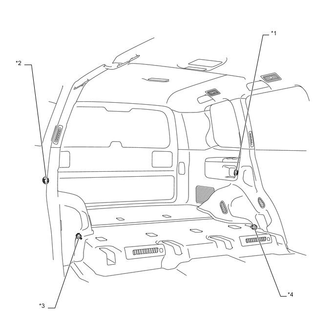
*1 Cooler Thermistor (Rear Room Temperature Sensor LH) *2 Cooler Thermistor (Rear Room Temperature Sensor RH) *3 Cooler Thermistor (Duct Sensor RH) *4 Cooler Thermistor (Duct Sensor LH) 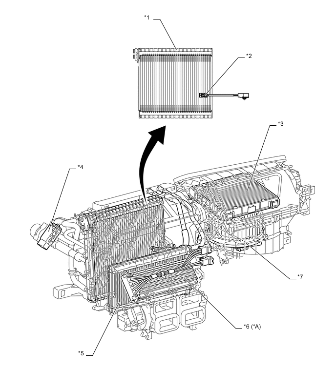
*A Models with Quick Heater Assembly - - *1 No. 1 Cooler Evaporator Sub-assembly *2 No. 1 Cooler Thermistor *3 Clean Air Filter *4 Cooler Expansion Valve *5 Air Conditioning Radiator Assembly *6 Quick Heater Assembly *7 Blower Motor with Fan Sub-assembly - - Figure 1. LHD Models
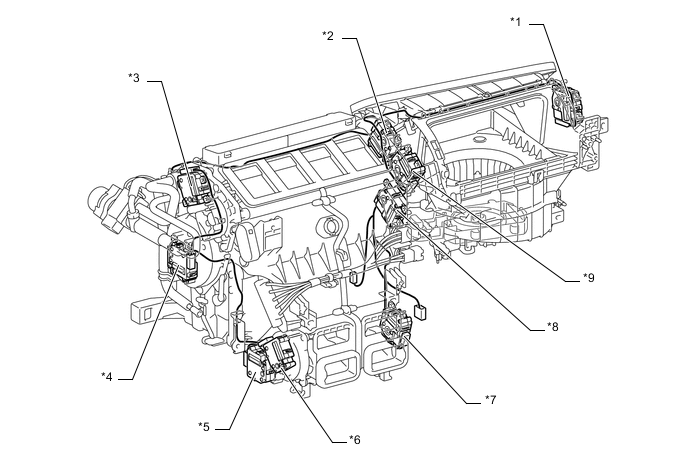
*1 Damper Servomotor (Recirculation/Fresh) *2 Cool Air Bypass Damper Servomotor *3 Mode Damper Servomotor LH *4 Air Mix Damper Servomotor LH *5 Air Mix Damper Servomotor (Rear LH) *6 Mode Damper Servomotor (Rear) *7 Air Mix Damper Servomotor (Rear RH) *8 Air Mix Damper Servomotor RH *9 Mode Damper Servomotor RH - - Figure 2. RHD Models
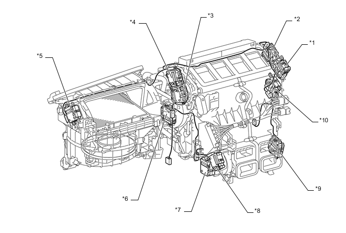
*1 Mode Damper Servomotor RH *2 Cool Air Bypass Damper Servomotor *3 Mode Damper Servomotor LH *4 DEF Mode Damper Servomotor *5 Damper Servomotor (Recirculation/Fresh) *6 Air Mix Damper Servomotor LH *7 Air Mix Damper Servomotor (Rear LH) *8 Mode Damper Servomotor (Rear) *9 Air Mix Damper Servomotor (Rear RH) *10 Air Mix Damper Servomotor RH 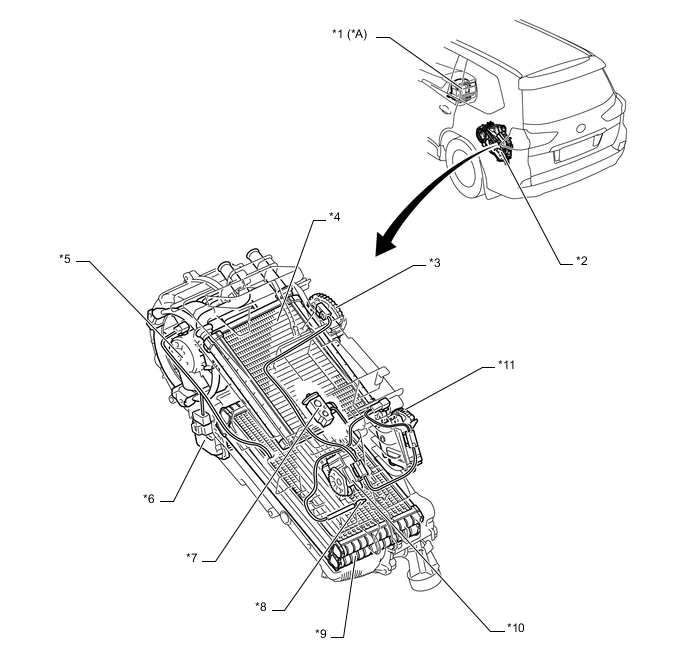
*A Models with Cooling Box Assembly - - *1 Cooling Box Assembly *2 Rear Cooling Unit Assembly *3 Rear Mode Damper Servomotor *4 Heater Radiator Unit Sub-assembly *5 Rear Blower Motor with Fan Sub-assembly *6 Blower Motor Control *7 Rear Cooling Unit Expansion Valve *8 No. 3 Cooler Thermistor *9 Evaporator Sub-assembly (Rear) *10 Rear Air Mix Damper Servomotor LH *11 Rear Air Mix Damper Servomotor RH - - -
SYSTEM CONTROL
-
The air conditioning system has been added the following controls:
Control Outline No. 1 Ion Generator Sub-assembly Control*
The air conditioning amplifier assembly operates the No. 1 ion generator sub-assembly, linked with the rotation of the blower motor. Tech Tips
*: Models with No. 1 ion generator sub-assembly
-
-
ION GENERATOR
-
nanoeTM*1are minute ion particles covered in water, with a ratio of approximately 1000 times more water than oxygen ions. nanoeTMalso have a slight acidity that is gentle on skin and hair.
-
nanoeTMcreated by the nanoeTMgenerator (No. 1 ion generator sub-assembly) installed in the instrument panel are blown out from the blower motor and released from the passenger side register.*2
Tech Tips
*1: nanoeTMis a trademark of Panasonic Corporation.
*2: There may be cases where nanoeTMdo not have a sufficient effect due to cabin conditions (temperature/humidity) or due to air flow volume or direction.
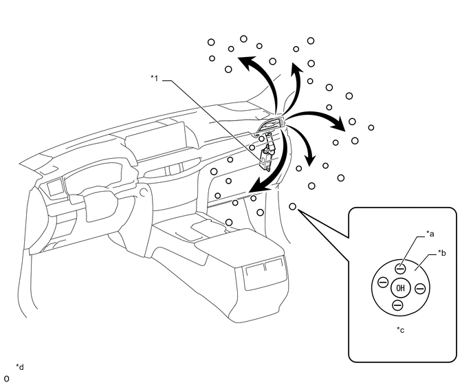
*1 No. 1 Ion Generator Sub-assembly - - *a Electron *b H2O
*c nanoeTM
*d Image Figure -
nanoeTMGenerator Operation
-
The nanoeTMgenerator (No. 1 ion generator sub-assembly) installed in the instrument panel is composed of a heat exchanger that uses a Peltier device and a nanoeTMgenerator that generates a high voltage. When current flows to the nanoeTMgenerator, it passes through the Peltier device, cooling the atomized electrodes within the nanoeTMgenerator. Then, the nanoeTMgenerator applies a high voltage to the liquid created through condensation on the atomized electrodes, creating nanoeTM.
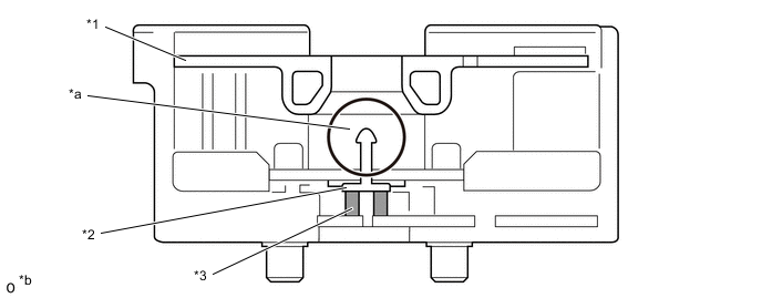
*1 Opposing Polar Plate *2 Atomized Electrodes *3 Peltier - - *a Condensation Water *b This illustration is only for explanatory purposes.
-
-
-
AIR CONDITIONING CONTROL PANEL (MODELS WITH NO. 1 ION GENERATOR SUB-ASSEMBLY)
-
The nanoeTM *1indicator has been added to climate display of the accessory meter assembly. In addition, the nanoeTMswitch has been added to the option display*2of the accessory meter assembly.
Tech Tips
*1: nanoeTMis a trademark of Panasonic Corporation.
*2: The option display is displayed by pressing the option switch of climate display.
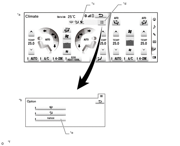
*a Climate Display *b Option Display *c nanoeTMIndicator
*d Option Switch *e nanoeTMSwitch
*f The illustrations shown are examples only.
-