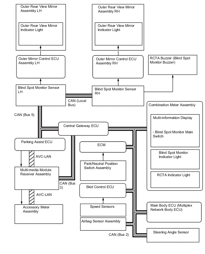
BLIND SPOT MONITOR SYSTEM
-
BLIND SPOT MONITOR FUNCTION
-
The blind spot monitor function operates when both of the following conditions are met:
-
The blind spot monitor main switch is on.
-
The shift lever is in a position other than R.
-
The vehicle speed is greater than approximately 16 km/h (10 mph).
-
-
The blind spot monitor function can detect vehicles in its detection areas.
-
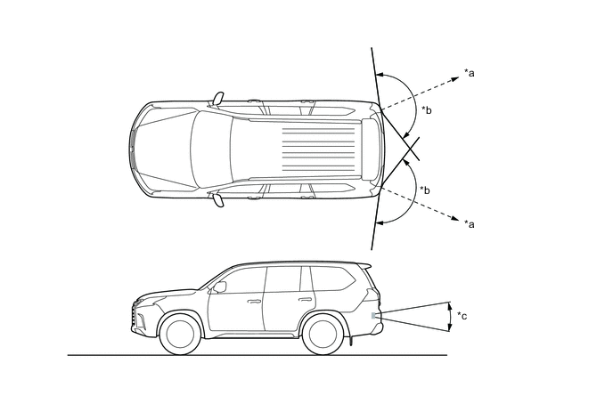
The detection areas formed by the blind spot monitor sensors LH and RH are as shown below:
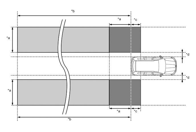
*a 3.0 m (9.8 ft.) *b 60 m (197 ft.) *c 1.0 m (3.3 ft.) *d 0.5 m (1.6 ft.) Tech Tips
If another vehicle that is rapidly approaching the vehicle's blind spot is detected, the notification timing is determined by the relative speed of the approaching vehicle. The notification timing for vehicles rapidly approaching the vehicle's blind spot can be customized. For details, refer to the Repair Manual.
-
-
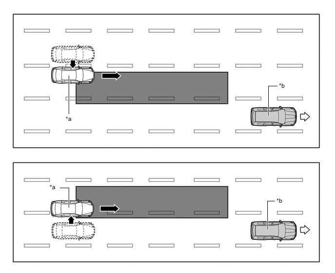
Detection Area (for Vehicle in Blind Spot)
-
When this vehicle is overtaken by another vehicle in an adjacent lane.
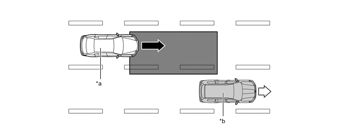
*a Other Vehicle *b This Vehicle 
Vehicle Speed (Fast) 
Vehicle Speed (Slow) 
Detection Area - - -
When another vehicle enters the detection area of this vehicle due to a lane change.
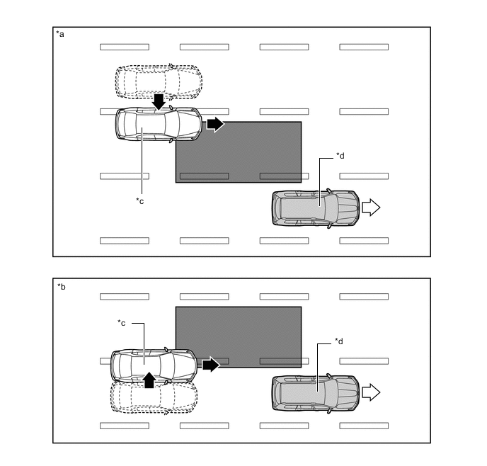
*a The other vehicle enters the detection area during lane change (merge in) (Type 1). *b The other vehicle enters the detection area during lane change (merge in) (Type 2). *c Other Vehicle *d This Vehicle Motion direction of other vehicle Motion direction of this vehicle Detection Area - -
-
-
Detection Area (for Rapidly Approaching Vehicle from Behind)
-
When another vehicle is rapidly approaching from behind.
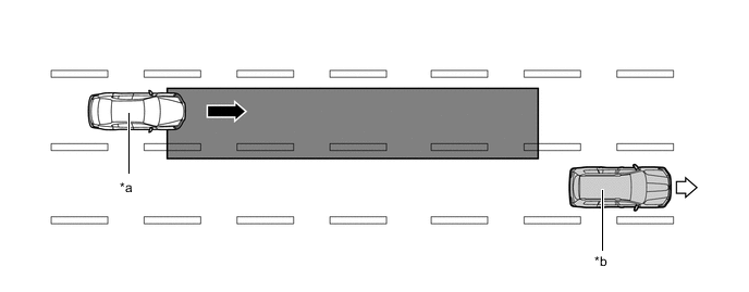
*a Other Vehicle *b This Vehicle Vehicle Speed (Fast) Vehicle Speed (Slow) Detection Area - - -
When another vehicle enters the detection area of this vehicle due to a lane change and approaches this vehicle.
*a Other Vehicle *b This Vehicle Motion direction of other vehicle Motion direction of this vehicle Detection Area - -
-
-
According to operation conditions, the blind spot monitor function promotes safety confirmation by using the outer rear view mirror indicator light to inform the driver that the system detects vehicles that are in or rapidly approaching the vehicle's blind spot.
-
The outer rear view mirror indicator light illuminates when a vehicle is in or rapidly approaching the vehicle's blind spot and the turn light switch is not operated. The indicator light flashes when a vehicle is in or rapidly approaching the vehicle's blind spot and the turn light switch is operated.
-
-
RCTA FUNCTION
-
The RCTA function operates when both of the following conditions are met:
-
The blind spot monitor main switch is on.
-
The RCTA switch is on.
-
The Shift lever position is R.
-
The speed of this vehicle is less than approximately 8 km/h (5 mph).
-
Target vehicle's speed is between approximately 8 km/h (5 mph) and 28 km/h (18 mph).
-
-
The RCTA function can detect vehicles in its detection areas.
-
The system continuously measures the relative speed of an approaching vehicle and its distance. If it is determined that the approaching vehicle will cross in the path of this vehicle, the Estimated Crossing Time (ECT) is calculated. When the ECT is 2.5 seconds or less, the system alerts the driver by flashing the outer rear view mirror indicator lights, illuminating the indicator in the accessory meter assembly, and sounding the RCTA buzzer (blind spot monitor buzzer).
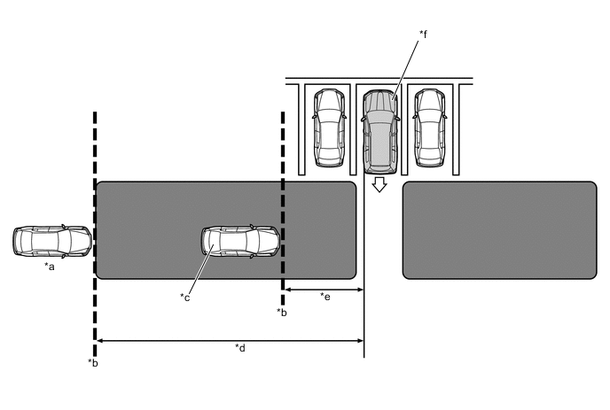
*a Target Vehicle (Approximately 28 km/h (18 mph)) *b Target Detection Line *c Target Vehicle (Approximately 8 km/h (5 mph)) *d Approximately 20 m (66 ft.) *e Approximately 5.5 m (18.0 ft.) *f This Vehicle Alert Area - -
-
-
Normal Parking
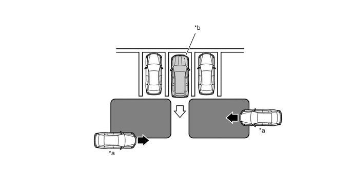
*a Target Vehicle *b This Vehicle Alert Area - - -
According to operation conditions, the RCTA function promotes safety confirmation by using the outer rear view mirror indicator lights and the RCTA buzzer (blind spot monitor buzzer) to inform the driver that another vehicle has entered the blind spot monitor sensor alert area of this vehicle.
-
When this vehicle is reversing, if a vehicle enters the detection area of the blind spot monitor sensors and it is determined the vehicle will cross the path of this vehicle, the system alerts the driver by flashing the outer rear view mirror and accessory meter assembly indicator lights and sounding the RCTA buzzer (blind spot monitor buzzer).
-
-
ACCESSORY METER ASSEMBLY
-
If an approaching vehicle is detected in the detection area when the multi-terrain monitor system is activated, the direction of the approaching vehicle is displayed on the accessory meter assembly.
Figure 1. Wide Rear View, and Side and Rear View (when outer rear view mirror assemblies are retracted)
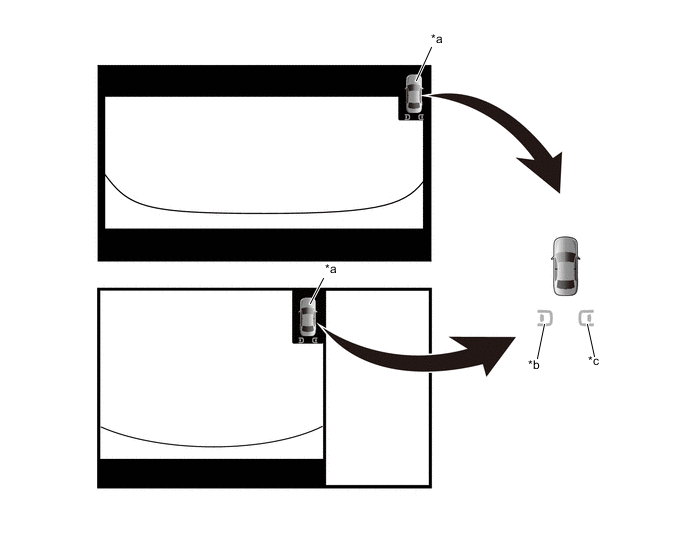
*a Vehicle Icon *b LH Side *c RH Side - - Tech Tips
The illustration shown is an example only. The illustration may differ from the actual vehicle screen.
Figure 2. Wide Rear View and Side Simultaneous View
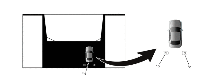
*a Vehicle Icon *b LH Side *c RH Side - - Tech Tips
The illustration shown is an example only. The illustration may differ from the actual vehicle screen.
Figure 3. Panoramic View
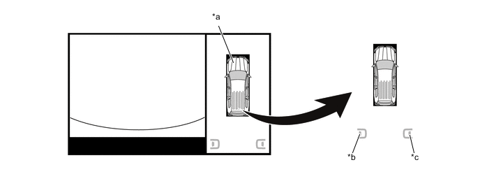
*a Vehicle Icon *b LH Side *c RH Side - - Tech Tips
The illustration shown is an example only. The illustration may differ from the actual vehicle screen.
-
The following item displayed on the multi-display is a warning of a system malfunction.

Tech Tips
The illustration shown is an example only. The illustration may differ from the actual vehicle screen.
-
Using the accessory meter assembly allows the user to customize the following items:
-
Brightness of the outer rear view mirror indicator light
-
Detection timing (4 stages)
-
Sound volume of the buzzer
-
-
-
BLIND SPOT MONITOR SENSOR
-
The blind spot monitor sensor consists of a millimeter wave radar circuit and a signal processing circuit.
-
The millimeter wave radar uses frequencies in the 24 GHz band.
*a Approx. 70 m (230 ft.) *b Approx. 150° *c Approx. 20° - - -
The distance to the object, azimuth and relative speed are calculated from the information that is provided by the reflected millimeter wave radar as described below:
Item Calculation Method Distance Calculated from the length of time that has elapsed from the time the waves of the millimeter wave radar have been emitted, until the reflected waves are received by the millimeter wave radar circuit. The distance is approx. 70 m (230 ft.). Azimuth Calculated from the reception angle of the millimeter wave radar reflections received. The detection angle has a horizontal range of approx. 150° and a vertical range of approx. 20°. Relative Speed Calculated by utilizing the change (Doppler effect*) that occurs in the frequency of the reflected millimeter wave radar waves. *: The Doppler effect causes the observer to perceive the radio waves emitted by a moving object to be a higher frequency as it approaches, and to be a lower frequency as it recedes. This phenomenon is created because when an object is located far away, the radio waves are perceived at higher frequencies than those of the radio source. An SST is used if radar axis confirmation is needed. For details, refer to the Repair Manual.
-