METER
-
LAYOUT OF MAIN COMPONENTS
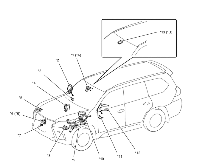
*A Models without Pre-crash Safety System *B Models with Pre-crash Safety System *1 Inner Rear View Mirror Assembly *2 Outer Rear View Mirror Assembly RH *3 Outer Mirror Control ECU Assembly RH *4 ECM *5 Headlight Sub Computer Sub-assembly *6 Millimeter Wave Radar Sensor Assembly *7 Front Television Camera Assembly *8 Headlight Main Computer Sub-assembly *9 Level Warning Switch Assembly (Windshield Washer Motor and Pump Assembly) *10 Skid Control ECU *11 Outer Mirror Control ECU Assembly LH *12 Outer Rear View Mirror Assembly LH *13 Forward Recognition Camera - - 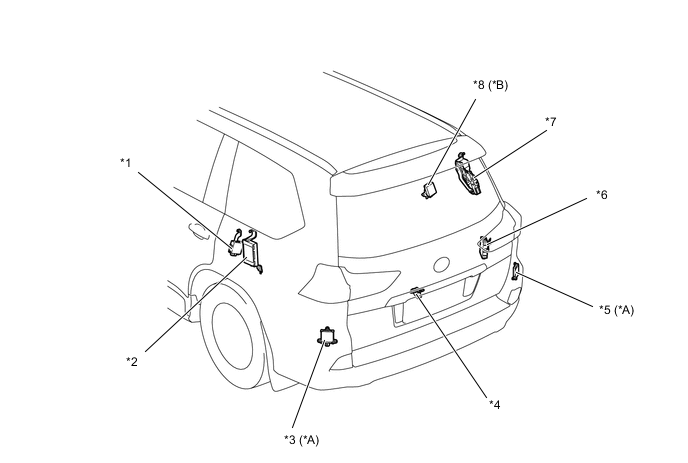
*A Models with Blind Spot Monitor System *B Models with Electrical Key and TPMS Receiver Assembly *1 Parking Brake ECU Assembly *2 Suspension Control ECU *3 Blind Spot Monitor Sensor LH *4 Television Camera with Dynamic Guide Line Assembly *5 Blind Spot Monitor Sensor RH *6 No. 2 Multiplex Network Body ECU *7 Power Back Door Unit Sub-assembly *8 Electrical Key and TPMS Receiver Assembly Figure 1. Models with 1VD-FTV Engine
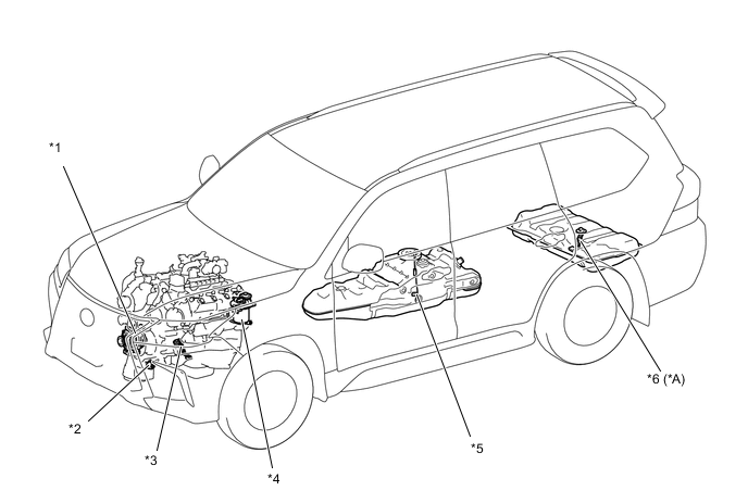
*A Models with Fuel Sub Tank Sub-assembly - - *1 Generator Assembly *2 Oil Pressure Sender Gage Assembly *3 Engine Oil Level Sensor *4 Fuel Filter Assembly *5 Fuel Sender Gage Assembly *6 No. 2 Fuel Sender Gage Assembly Figure 2. Models with 3UR-FE Engine
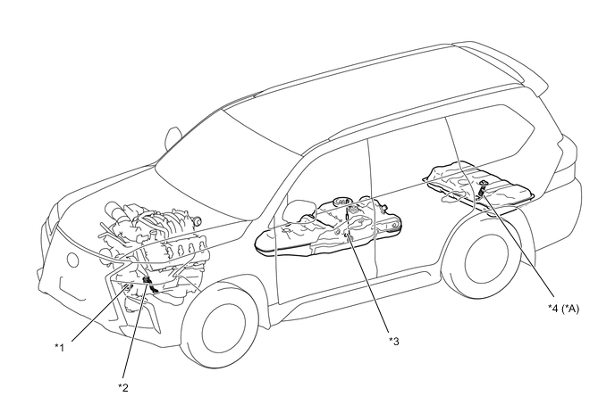
*A Models with Fuel Sub Tank Sub-assembly - - *1 Oil Pressure Sender Gage Assembly *2 Engine Oil Level Sensor *3 Fuel Sender Gage Assembly *4 No. 2 Fuel Sender Gage Assembly 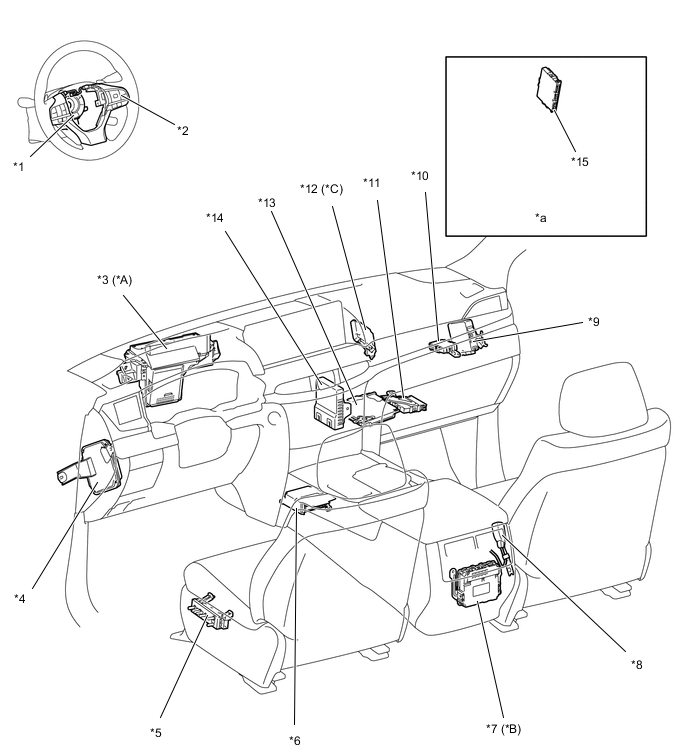
*A Models with Headup Display *B Models with G-BOOK System *C Models with Pre-crash Safety System - - *1 Spiral Cable Sub-assembly *2 Steering Pad Switch Assembly *3 Meter Mirror Sub-assembly *4 Steering Control ECU *5 Front Power Seat Switch LH *6 Air Bag Sensor Assembly *7 DCM (Telematics Transceiver) *8 Front Seat Inner Belt Assembly RH *9 4 Wheel Drive Control ECU *10 Network Gateway ECU *11 Clearance Warning ECU Assembly *12 Driving Support Computer Assembly *13 Parking Assist ECU *14 Air Conditioning Amplifier Assembly *15 Smart Key ECU Assembly - - *a Refer to the Service Bulletin for the installation position of the part. - - 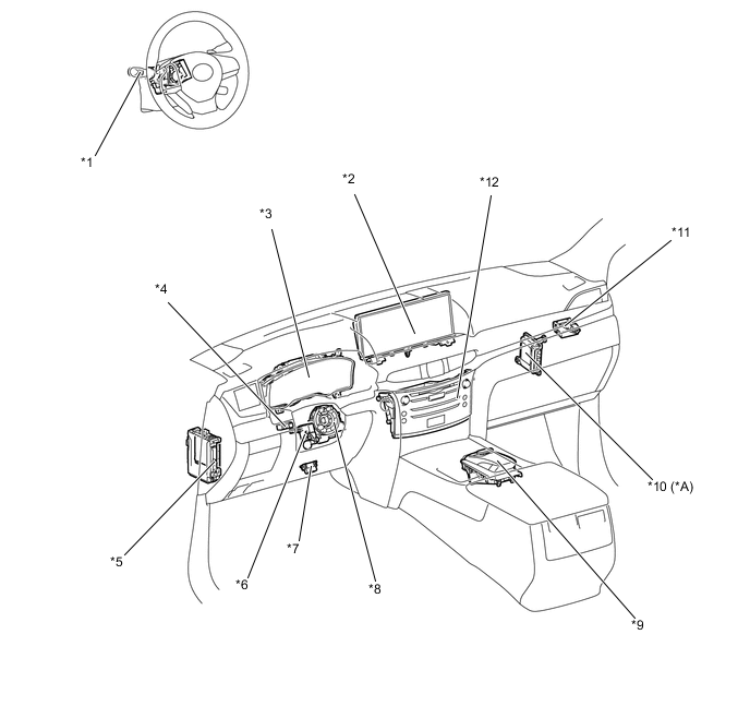
*A Models with 3UR-FE Engine - - *1 Headlight Dimmer Switch Assembly *2 Accessory Meter Assembly *3 Combination Meter Assembly *4 Light Control Rheostat *5 Main Body ECU (Multiplex Network Body ECU) *6 Multiplex Tilt and Telescopic ECU *7 DLC3 *8 Steering Sensor *9 Remote Operation Controller Assembly *10 Transmission Control Computer Assembly *11 Power Steering ECU Assembly *12 Multi-media Module Receiver Assembly Figure 3. Models with Rear No. 2 Seat with Automatic Folding-up
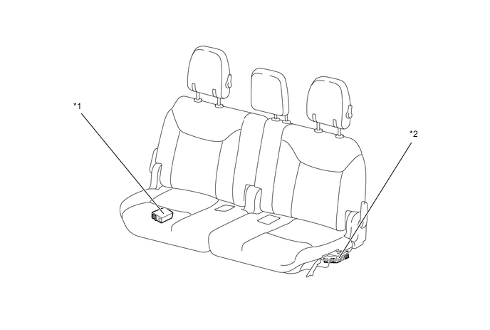
*1 Fold Seat Control ECU RH *2 Fold Seat Control ECU LH